IR Group
PROJECT SPECIFICATION
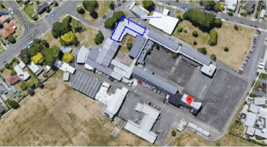
Naenae College Administration Upgrade
910 High Street
Avalon
Lower Hutt
Issued for Tender/Consent
26 Jul 2022
Scope
This contract is for the interior upgrade of Block YA (Administration block) at Naenae College, High Street, Lower Hutt as descriibed below. All work is to be carried out to the best of trade practise and in accordance with all relevant standards, manufacturer's instructions and the NZ Building Code. Please check all dimensions on site. Allow to complete the following items of work.
Note: All exterior renovation of the building to be designed by Resolve Architects. This includes reroofing the building, design of the entrance portico, ramp and stairs, specifying all exterior doors and windows and any additional exterior features and specifying the mechanical ventilation system for the three WC's.
Demolition - Interior
Uplift all existing carpet and flooring and prepare floors as necessary for new floor coverings
Remove interior walls and doors at locations shown in drawings.
Remove any wall coverings (e.g. Autex) and prepare wall linings for new Autex Composition, Resene paint or Plytech wall lining as shown on interior elevations
Remove light fittings, pin boards, fixtures and features and sanitary fixtures in both toilets adjacent to the hall foyer.
Dispose of all removed debris from site.
General New Work - Interior
-
· Construct new timber framed interior walls, at locations shown in drawings, using 90x45 H1.2 framing at 400crs. Fit additional dwangs as required for
interior joinery and the like. Allow for new scotias, skirtings & architraves to new work as indicated in drawings.
-
· Wall linings to be as follows:
o All new walls to be lined with 10mm GIB or GIB product specified by Engineer in Bracing Plan OR 12mm Plytech as specified
o GIB to be F4 where painted and F1 where covered with Autex Composition or Exoply wall lining
-
· Frame and line interior walls where doors and windows are removed
-
. Remove ceiling linings and replace with new 13mm GIB on GIB Rondo battens where indicated on Reflected Ceiling Plan. Allow to paint in Resene Ceiling White
-
· Supply and install new vinyl and carpet tiles as shown on the floor coverings drawing
-
· Supply & install new interior doors, interior sliding transaction windows and interior glass partitions as shown in the drawings
-
· Supply & install new interior joinery in reception, admin office, sick bay and kitchen
-
· Supply and install new sanitaryware and accessories in three WC's (adjacent to the hall foyer)
Electrical
-
· Disconnect and make good services for demolition.
-
· Supply and fit new light fittings, with associated light switches and wiring to suit, at locations shown & as detailed in drawings.
-
· Where possible, run any new wiring in wall cavities/ceilings before new linings are fitted.
. Supply and install new ceiling mounted radiant heaters as indicated in the drawings
Plumbing and Drainage
-
· Disconnect and make good services for demolition.
-
· Allow to run hot and cold water supply to all WHB's (sick bay, WC's 1 to 3, medical) and kitchen sink
. Allow to run cold water to toilet cisterns (WC1, 2 and 3)
Floor Finishes
-
· Supply and install Tarkett Granit vinyl flooring in kitchen, sick bay and WC's 1 to 3
-
· Vinyl is to be coved 150mm up the adjacent walls with a stainless steel trim, and coved up the toe kicks of the sick bay and kitchen joinery
-
· Supply and fit new entrance matting as shown in drawings
-
· Supply new carpet tiles throughout as shown in drawings. Carpet tiles to be selected.
Painting
-
· Paint all existing and new wall and ceiling linings, existing timber doors & frames, timber window frames & all new and existing timber trim throughout the areas being renovated
Doors
-
· Allow to supply and install interior powdercoated aluminium and glass paneled doors and interior doors as indicated on door schedule.
Address
|
Site Address |
910 High Street |
|
Suburb |
Avalon |
|
City |
Lower Hutt |
|
Lot # |
Lots 1 and 2 DP18397 and Part Lot 1 DP19671 |
Site Conditions
|
Wind Zone |
VH - Very High Wind Speed |
|
Earthquake Zone |
Zone 3 |
|
Exposure Zone |
Zone C - Medium |
|
Snow Loading Zone |
Zone N1 |
TABLE OF CONTENTS
Plytech Plywood Interior Linings38
Mammoth Polyester Insulation53
Autex Interior Acoustic Treatments & Finishes62
Commercial Vinyl Surfacing from Jacobsen 68
Carpet & Resilient Floor Coverings73
GIB General Wall and Ceiling installation86
T+R Interiors Eclipse 64mm Aluminium Suite 86
Phonic Ceiling Tiles - data sheet86
Phonic Ceiling Tiles - installation guide 86
Advanced Flooring Gold Coast 86
Advanced Flooring Evertread 86
Supreme Classic soap dispenser86
Tork Mini Jumbo Toilet Roll Dispenser86
Mechanical Ventilation for WC's 86
The Contract Documents are complementary and comprise this Specification, the accompanying drawings, the NZ Standards Contract NZS 3910 together with Schedules as specified below, any written documentation clarifications issued during tendering/estimating, any manufacturer/supplier information issued with this Specification, any list of agreed Subcontractors, the contract establishment letter and any other relevant correspondence, and any Site Instructions or additional details or instructions issued as Variations. (The NZS 3910 Contract will be emailed upon request).
If the Architect/Designer has not been engaged to administer the Contract or observe the works, then the term Architect/Designer, where referred to in this specification, means Contract Administrator.
These Project Specific Conditions supersede the Standard Conditions where they are in conflict. Refer any ambiguity or apparent discrepancy within or between any Contract Documents to the Architect/Designer, whose interpretation shall be binding on all parties.
Ensure that all Trades are aware of all Conditions and that subcontract prices are accepted on this basis, and in a form acceptable to the Registered Master Builders Federation or the Certified Builders Association. Ensure that all persons engaged on the works are aware of all items in this specification and on the drawings that may in any way affect their section of the works.
Relevant site conditions are believed to be correctly represented in the Contract Documents, however the Contractor (and Subcontractors where appropriate) are requested to inspect the site to ascertain for themselves the nature and extent of the works and the rights and interests that may be interfered with in the execution of the works, as no claims for additional payment will be recognised on the grounds of insufficient description.
Carry out whatever actions or precautions are required to avoid or to absolutely minimise noise, dirt, dust, access, etc. inconvenience or disruption of any nature to the adjacent owners or tenants. Indemnify the Principal against any claims arising from this source.
Take all appropriate precautions to protect all third party property, services, etc., and indemnify the Principal against any claims arising from the construction operations. Any damage to third party property caused by construction activities or failure to protect shall be rectified as soon as possible by the person causing the damage, or by appropriately qualified trades-persons employed by the person responsible for the damage if necessary.
Suspend operations during weather which would affect the quality of work in progress. Secure the works as soon as possible against adverse weather, dust and vandals. Avoid structural damage that is caused by overloading.
Adequately protect all finished work and maintain until the date of Practical Completion. Each trade shall protect the work of all other trades, and each trade is responsible for making good any damage they cause to finished works. Arrange special protection as required for windows and doors, finished timber work, plumbing fittings and hardware, cabinets and other joinery, and similar items.
The Contractor will be held responsible for the full period of his legal responsibility in connection with this Contract for ensuring that all work execution, materials, and fittings, are completely in accordance with Contract requirements.
The Contractor is responsible to the Principal for the appropriateness and fitness, in relation to a reasonable expectation or requirement, of all of the materials and workmanship incorporated into the works by himself or his subcontractors; for this reason few specific guarantees are required in these contract documents. The terms and conditions of any warranty or guarantee required or provided shall not in any way negate the minimum remedies available under common law as if no warranty or guarantee had been furnished.
No apparent expression of the Architect's/Designer's reasonable satisfaction shall be deemed to be acceptance of defective materials or workmanship within the terms of the Contract or to be an authority for any Variation except where such Variation is authorised as provided for in the Contract. Instructions that are given verbally are deemed to be instructions for proper execution of the works and do not involve extra charges.
Workmanship in all trades is required to be equal to or better than recognised good trade practice. The Contractor shall provide all necessary setting out information and component dimensions for subcontractors and shall check and be responsible for the accuracy of their work.
Should any tradesperson consider that the surface finish or general conditions of previous work are unsatisfactory to ensure a proper finish for their own work thereon, that tradesperson shall give immediate notice to the Contractor or Architect/Designer as appropriate and shall not proceed until all necessary improvements have been made. Failing such notice the trade concerned will not be relieved of responsibility for a poor finish due to such unsatisfactory condition.
Specialist Finishes Subcontractors are responsible for ensuring that substrates are completely appropriate for them to achieve first class results, and to this end shall, in sufficient time, instruct the Contractor with regard any fixings, primings, sealings or whatever for the substrate that vary in any
way from the substrate manufacturer's standard recommendations. The Contractor shall advise the Architect/Designer with regard these variances, and not proceed until the Architect/Designer has agreed to them.
The Contractor and all Subcontractors affected shall be jointly and severally responsible for completion of the whole of the works in a completely watertight condition and shall therefore examine all details to be satisfied that this condition can be achieved. If any detail is considered unsatisfactory the Architect/Designer shall be notified immediately and he/she will then either interpret the detail to the Contractor's satisfaction, or accept responsibility for watertightness at the points in question, always assuming reasonable workmanship.
Ensure that all materials or items incorporated into any particular construction or finish are compatible and that their individual use is approved by the manufacturers and/or suppliers of the other parts of the system.
For all electronic/electrical/mechanical operating systems all work and all necessary materials and items incidental to the primary item specified, that are incorporated into the works, shall be such as to leave a neat, efficient, easily maintained and robust installation, completely in accordance with all of the recommendations of the primary items' manufacturers. Where appropriate, source all parts of a system from a single supplier or manufacturer.
The Contractor shall make provision for all temporary works and services required for the satisfactory completion of the contract works. The Contractor shall pay all associated costs and fees; carry out all necessary maintenance, alterations and servicing requirements; and remove temporary works and services on completion of the contract works. Temporary works and services shall comply with the requirements New Zealand Building Code.
This Specification covers contract administration, standards, materials quality, workmanship and the scope of works only: the exact nature of the works and all specialist items, descriptions, etc., are contained on the drawings, which also take full precedence.
All clauses in all specification sections apply to their full extent and meaning to the entire Contract. Trade sections and paragraphs have been introduced into this specification for reference only and it shall not be construed that each trade section is a complete segregation of the materials and labour of that trade. The onus is on all trades to be conversant with any and all clauses which in any way affect their work.
(Be aware that the ‘scope’ noted in the ‘Project Overview’, and scope and general extent clauses within this specification, are included to provide a general indication only and must NOT be interpreted as schedules of quantities - the exact nature and extent of all aspects of the works are shown on the drawings).
New Zealand Standards (NZS), Australian Standards (AS), Joint Standards (AS/NZS), British Standards (BS), Acts of Parliament, Regulations made thereunder, Codes of Practice, and any specific Manufacturer's Instructions or Manufacturer's Recommendations that are referred to in these Contract Documents shall all be deemed to be the latest published edition thereof at the time of drawings issue, and shall be followed by the Contractor and all Subcontractors to the full extent applicable consistent with the intent of this Contract. Documents cited within other cited publications are deemed to form part of this specification.
Where Standards have a number of Divisions, e.g. AS/NZS 3500.1, AS/NZS 3500.2, etc., each of the Divisions relevant to this project is deemed to form part of this specification.
Retain current copies of significant cited documents and manufacturer's technical literature on the site.
Comply with all relevant provisions of the NZ Building Code, and with all relevant territorial or statutory authority regulations, by-laws, obligations, etc. Give all required notices.
The Principal has obtained a Land Use Consent. The Principal has applied for and paid for the Project Information Memoranda, the Building Consent and other approvals required for the works to start. The PIM and Building Consent will be forwarded to the Contractor as quickly as possible after they are issued by the Territorial Authority. Note: It is an offence under the Building Act to carry out work not in accordance with a Building Consent.
Should the Building Consent be subject to any conditions which modify the requirements of the Contract Documents in any way, the Architect/Designer reserves the right to negotiate any or all of these modifying conditions with the Building Consent Authority. If after these negotiations additional work is required, it will be handled as a Variation to the Contract.
The Principal will apply for the Code Compliance Certificate (CCC) and any other licenses or approvals for the building to be used. However, Practical Completion will NOT be certified until the CCC inspection has occurred and any additional works required by the local Building Consent Authority have been completed. To this end it is recommended that the Contractor obtains all required certificates, guarantees, Producer Statements, as-built drawings, etc., required for the CCC application as work proceeds, to facilitate application for the CCC as soon as the works are completed. For his part, the Principal hereby undertakes to apply for the CCC within one day of all required material being in hand. Likewise, the Contractor should have capacity available to attend as quickly as possible to any items identified by the Building Consent Authority as being required prior to the issue of the CCC.
Coordinate the works of all trades to ensure efficient progress of the works. Ensure that all holes, sleeves, penetrations, supports, etc., that are required for services are correctly incorporated as work proceeds. Identify and sufficiently forward-notify the appropriate persons of all deadlines for the supply of fittings, components, information, etc.
Except where they are clearly to the contrary, all dimensions are deemed to be to the bare surface of concrete, masonry, timber framing or other basic construction material. All figured dimensions take precedence over scaled sizes. Where any detail is included in more than one drawing the larger scale detail takes precedence. Where any ambiguity exists refer to the Architect/Designer for interpretation.
The word ‘provide' and the word ‘fix' used separately in the Documents shall be taken to mean ‘provide and fix' unless otherwise stated.
When the term ‘allow' occurs in the Documents, except with reference to Monetary Allowances, the cost of the item shall be at the risk of the Contractor.
The terms ‘approved', ‘directed', and ‘selected' when used in the Documents refers to the approval, direction or selection of or by the Architect/Designer. Please give adequate notice of when these decisions are required. ‘Architect/Designer' shall mean the Architect or Designer, their representative or any Consulting Engineer engaged by the Architect/Designer.
The Contract Documents show the extent and nature of the works but there is no warranty expressed or implied that they show each and every minor detail or item required to be included by the Contractor. Should any material, structural member, fixing, or item or work appear to be inadequately described, yet obviously necessary for the neat, strong and satisfactory completion of the work, it shall be incorporated into the Contract Works.
Comply with the Health and Safety at Work Act 2015 (HSWA), and with all relevant Health and Safety at Work Regulations 2016, and with all relevant WorkSafe New Zealand (WorkSafe) Approved Codes of Practice and WorkSafe Information and Guidance, particularly those for construction and building maintenance. Comply with the relevant provisions of the New Zealand Building Code, in particular Clause F5.
So far as is reasonably practicable and according to a PCBU's (person conducting a business or undertaking) primary duty of care, take all necessary steps required to make the site and the contract works safe, and to provide and maintain a safe working environment. Ensure that all those working on or visiting the site are aware of the site safety rules and are not unnecessarily exposed to hazards.
Each PCBU, so far as is reasonably practicable, must ensure the health and safety of workers, and that other people are not put at risk by its work. If more than one PCBU has a duty in relation to the same matter, each PCBU with the duty must, so far as is reasonably practicable, consult, co-operate with, and co-ordinate activities with all other PCBUs who have a duty in relation to the same matter.
PCBUs can enter reasonable agreements with other PCBUs to meet their duties, but cannot contract out of their duties.
Notify WorkSafe as soon as possible when a notifiable event occurs. Take all reasonable steps to preserve the site of the notifiable event in accordance with WorkSafe requirements. Ensure that the site of the event is not disturbed until authorised otherwise by WorkSafe. Keep records of all notifiable events.
Scaffolding shall comply with all Statutory and Local Authority Regulations, with the WorkSafe 'Best Practice Guidelines for Scaffolding', AS/NZS 1576 (Scaffolding equipment), AS/NZS 4576 (Guidelines for Scaffolding), and AS/NZS 4994 (Roof edge scaffolding), and shall be maintained for the duration and removed on completion.
The use of ballistic fixings must absolutely comply with all relevant safety recommendations at all times. No rubbish fires are allowed on site. Portable/personal disc/tape players, radios and iPods must not be used anywhere on the site. No smoking on site, except in the designated location in accordance with the Smoke Free Environments Act 1990, the location of which will be determined by the Contractor, with the approval of the Principal.
A PCBU's primary duty of care includes, but is not limited to, so far as is reasonably practicable:
-
- providing and maintaining a work environment that is without risks to health and safety;
-
- providing and maintaining safe plant and structures;
-
- providing and maintaining safe systems of work;
-
- ensuring the safe use, handling and storage of plant, structures and substances;
-
- providing adequate facilities for the welfare at work of workers in carrying out work for the business or undertaking, including ensuring access to those facilities;
-
- providing any information, training, instruction, or supervision that is necessary to protect all persons from risks to their health and safety arising from work carried out as part of the conduct of the business or undertaking;
-
- monitoring the health of workers and the conditions at the workplace for the purpose of preventing injury or illness of workers arising from the conduct of the business or undertaking.
Before commencing work on the site, the Contractor shall prepare and submit to the contract administrator a health and safety plan. The health and safety plan shall include, but not be limited to: - the health and safety of all people on the site and on other properties, and the general public;
-
- identification of existing and potential construction hazards and risks;
-
- safety procedures to eliminate, isolate or minimise construction hazards;
-
- the equipment to be used to minimise the hazards;
-
- the maintenance of a register of hazards for the site;
-
- the name and qualifications of the site safety person;
-
- emergency procedures;
-
- first aid facilities and safety equipment;
-
- the methodology for notifying, recording and investigating accidents and injuries.
Carry out all construction operations in accordance with the submitted health and safety plan.
The Architect/Designer will issue Site Instructions (SI) to amend or clarify the works. Upon receipt of a SI the Contractor shall immediately notify the Architect/Designer if he believes there are price or timing adjustment implications. The Architect/Designer will then issue a Variation Price Request (VPR) for pricing of the possible Variation by the Contractor, within the time stipulated, or within 10 days if no time is stipulated. If the Contractor does not return the VPR within the time stipulated the Architect/Designer will assess it at reasonable rates. Once agreement is reached on price and/or timing a Variation Order (VO) for the item will be issued. Note that works covered by a SI or a VPR must NOT be actioned until the VO is issued.
When a Variation is contemplated and timing does not allow SI and VPR action the Contractor is to advise, and record in the site diary, an estimate of price and timing implications. If accepted by the Architect/Designer, a VO will be issued immediately. The Contractor shall then co-operate with the Architect/Designer to establish agreed pricing.
Claims for Variations neither priced nor estimated prior to being put in hand (but considered valid) will be incorporated into Progress Payment Certificates or the Draft Final Accounts as claimed and accepted but with a proviso allowing 5 (five) days for written objections by either the Principal or the Contractor, to any aspect of them, for further consideration.
The Main Contractor's Variations Margin agreed pre-contract will be the maximum accepted for any trade unless higher rates are nominated pre-contract and are accepted. The Main Contractor's agreed Variations Margin shown shall be deemed to include all preliminary and general costs, overheads, variation processing costs, and profit. If no margin is given, a 5% overall margin will be applied.
Note that ‘loss of anticipated profit' claims consequent upon reduction of works extent will NOT be recognised, and that the cost of processing Variations is deemed to be included in the P & G Allowance.
Also note that for Variations pricing all materials shall be charged at the actual net invoiced cost plus margin; i.e. recognised ‘Trade Price’, volume discounted where appropriate.
Progress Claims shall be in writing, shall be in accordance with the requirements of the Construction Contracts Act 2002, and shall include all of the following:
-
- The overall amount claimed.
-
- The percentage completion and amount claimed for each Subcontractor. For accurate claim verification please ensure that this breakdown exactly matches the trades costs breakdown agreed-to
pre-contract.
-
- The total Contract Sum Adjustment for any/all Variations authorised prior to the claim.
-
- Items covered by Monetary Allowances listed separately.
-
- And, if specifically requested, confirmation that amounts previously claimed on behalf of Subcontractors, certified by the Architect/Designer, and paid by the Principal, have actually been paid to the Subcontractor (apart from normal retentions).
Note that retentions will be held exactly in accordance with the Conditions of Contract.
Clear construction debris and rubbish from the works at regular intervals, and additionally if so instructed by the Architect/Designer. Clean each space thoroughly before commencing any finishing works.
In preparation for the Practical Completion inspection carry out the following:
-
- Clean the works thoroughly, removing all debris, surplus materials, splashes, marks, temporary markings, etc. (All cleaning methods and materials shall be as recommended by the manufacturer of the item being cleaned).
-
- Remove protective wrappings and coverings unless otherwise directed.
-
- Touch up minor painting faults, carefully matching colour, and brushing out edges. Repaint any badly marked surfaces back to suitable break-lines.
-
- Adjust, ease and/or lubricate as required all doors, drawers, controls and other moving parts to ensure their efficient operation.
-
- Any other works required to leave all spaces ready for immediate occupation and all electronic/electrical/mechanical systems fully operational.
-
- Clean out all spoutings, gutters, downpipes, and gullies and flush out all drains.
-
- Clean all sanitary appliances and check all aspects of the water services.
-
- Thoroughly re-inspect all aspects of the works (and have any defects fully rectified) to be certain that the works are completely ready for the Practical Completion inspection - if an unreasonable number of items are noted by the Architect/Designer during the inspection it will be terminated and then rescheduled for at least a week forward to allow proper completion to be achieved.
(Note that a Code Compliance Certificate must be obtained before Practical Completion will be certified. Obtain all required certificates, guarantees, as-built drawings, etc., as work proceeds to enable the CCC application to be submitted as soon as construction is completed).
2
Preliminary
Refer to General Conditions of Contract and the Special Conditions in this Specification as appropriate. Read this section in conjunction with all other trade sections.
Comply with the New Zealand Building Code 1992 including all revisions and amendments, Verification Methods where appropriate, and construction principles that are embodied in the Acceptable Solutions.
Comply with all relevant provisions and recommendations of:
NZBC F1 Hazardous Agents on Site
NZBC F2 Hazardous Building Materials
NZBC F3 Hazardous Substances and Processes
NZBC F4 Safety from Falling
NZBC F5 Construction and Demolition Hazards
Carry out the partial demolition to the buildings and structures as indicated for demolition on the approved drawings, including those that are located below ground level, and remove and dispose of all resulting demolished debris. Aspects of this work include the provision of all precautionary safety measures, screens, scaffoldings, hoarding, covered walkways and the like necessary for carrying out and completing the demolition work. All aspects of this work shall be carried out to comply with the requirements of the NZ Building Code, relevant Regulations and Acts, the controlling Territorial Authority, and as specified herein.
Comply with the Health and Safety at Work Act 2015 (HSWA), and with all relevant Health and Safety at Work Regulations 2016, and with all relevant WorkSafe New Zealand (WorkSafe) Approved Codes of Practice and WorkSafe Information and Guidance.
Comply with all relevant WorkSafe NZ Approved Codes of Practice and Information and Guidance requirements; in particular the NZDAA 'Demolition - Best Practice Guidelines for Demolition in New Zealand', and the 'OSH Guidelines For the Provision of Facilities and General Safety in the Construction Industry'.
In addition to all other compliance requirements for general demolition, the removal, transportation and disposal of asbestos and Asbestos-Containing-Materials (ACMs) shall comply with the Health and Safety at Work (Asbestos) Regulations 2016, and with the 'Management and Removal of Asbestos Approved Code of Practice' (ACOP).
Prepare and submit an Asbestos Management Plan conforming to the requirements of the ACOP that clearly outlines the management, handling and removal of asbestos materials.
Confirm all local authority and WorkSafe NZ requirements for asbestos materials before commencing demolition. Only certified asbestos removers with a current Certificate of Competence for Restricted Work with Asbestos shall carry out work associated with asbestos materials and ACMs.
Allow for all work associated with the safe and orderly execution of the demolition work, including complying with all Territorial Authority requirements, Building Consent, Building Act, Health and Safety requirements, and all other acts, laws, by-laws and regulations that may affect the execution of the works.
Notify WorkSafe NZ of work that is notifiable (particular hazardous work) under the Health and Safety in Employment Regulations 1995, 24 hours before starting the work.
The times during which demolition work may be carried out is restricted. Comply with all conditions of the Building Consent. Do not carry out demolition work outside the permitted times.
Demolition work shall be carried out by suitably skilled and experienced workers and operators trained for this type of work, including the necessary demolition methods and the maintenance and inspection of demolition plant and equipment. Carry out demolition work in a careful manner so as to avoid damage to existing buildings, structures or property not scheduled for demolition and to be retained
Ensure that supervisory personnel have a detailed knowledge of the precautions and procedures outlined in the WorkSafe NZ 'Demolition - Best Practice Guidelines for Demolition in New Zealand'.
Notify the Contract Administrator the name of the appointed demolition supervisor prior to commencement, who shall be the holder of a current safety qualification recognised by WorkSafe NZ. Evidence of this shall be made available to the Contract Administrator.
All practicable steps must be taken for the safety of employees, and equipment must be operated by competent people. Particular care must be taken when employees demolish unsafe or damaged structures such as brittle roofing, fire-damaged and cantilevered structures.
Provide all necessary shoring or strutting or other protection to ensure complete safety and protection throughout the contract.
Protect public footpaths, kerbs, gutters, crossings, etc., (and keep them free and clear of debris or excavation material), and pay all charges in connection with any damage rectification. Ensure that roads and paths are not obstructed and the traffic is not impeded while the work is being carried out.
Where there is a danger to the public, warning signs, barricades or warning devices must be provided and used.
Notify the Contract Administrator immediately of any services or conditions or constructions encountered which are inexplicable or not anticipated on the drawings or in this specification. Removal, disconnection, relocation or otherwise for these shall all be as directed and carried out by appropriately qualified tradespersons.
The Principal has the right to remove any fixtures and fittings, and to demolish or remove any part of the building, before the building is handed over to the Contractor.
Carefully dismantle and remove any materials and items that are scheduled or identified otherwise for reuse. Store and protect these from damage, weather and contamination until completion of the works or as directed.
All materials, debris and other items arising from demolition shall become the property of the Contractor unless specifically stated otherwise, and due allowance for the credit value (if any) of such materials, items, etc., shall be made in the tender.
Apart from those items scheduled for salvage or reuse all demolition material becomes the property of the Contractor, and together with rubble shall be removed from the site as quickly as possible.
Remove all demolition rubble and waste material off the site to an approved landfill, and in such a manner as to cause as little inconvenience as possible to the adjoining owners and the public. Pay all associated landfill and disposal fees.
Remove demolition rubble, waste and salvaged materials continually from the site through the period of the demolition, and do not allow these to accumulate on site.
The burning of demolition waste on the site is not permitted.
Take full responsibility for:
-
- Giving all required notices to the water, sewage, gas, telecoms and electricity authorities or companies, and the Territorial Authority, and paying all relevant fees and charges.
-
- Removing, disconnecting, sealing off, etc., existing service lines and items that are to be made redundant.
-
- Protecting existing services lines and items that are to be retained.
-
- Maintaining existing services to occupied areas of the building and/or site.
-
- Rectifying any damage or interference to existing services that are to be retained, and providing temporary services while repairs are being carried out.
-
- Protecting services adjacent to the site.
Check the relationship and the condition of adjacent buildings, structures and areas. No part of the demolition process shall adversely affect the integrity of adjacent buildings, structures or areas to be retained.
Take all necessary measures to minimise nuisance from dust, noise and other causes affecting adjoining areas, properties and the public.
Refer to NZS 6803 'Acoustics - Construction noise', and comply with the requirements of the Building Consent (as applicable). Use appropriate plant, equipment and machinery so as to comply with required noise limits.
Make all necessary allowances to reinstate and make good any damage caused by the demolition work to any existing building or property, including site, being retained. No reinstatement or making good work shall be undertaken without prior assessment and instruction from the Contract Administrator.
Ensure that all demolition work has been carried out to the required standard, including the disconnection and sealing off of redundant services.
Leave the site clear of all demolition rubble, waste materials and disturbed ground to the required standard.
Remove all associated machinery, plant, tools, equipment, etc., from the site.
Check that any remedial work associated with demolition damage to other buildings or property or retained area of the site has been carried out to the requirements and satisfaction of the Architect/Designer.
Check that any materials and/or items salvaged on behalf of the Owner have been handed over to the Owner and are no longer the responsibility of the Contractor.
Provide copies of all necessary compliance documents to the relevant parties.
|
IR Group |
Naenae College Administration Issued for Tender/Consent Upgrade |
Refer to General Conditions of Contract and the Special Conditions in this Specification as appropriate. Read this section in conjunction with all other trade sections.
Comply with the New Zealand Building Code 1992 including all revisions and amendments, Verification Methods where appropriate, and construction principles that are embodied in the Acceptable Solutions.
Comply with all relevant provisions and recommendations of:
|
2097:2006(AS/NZS) |
Methods for sampling veneer and plywood |
|
2098.0:2006(AS/NZS) |
Methods of test for veneer and plywood - General introduction and list of methods |
|
2270:2006(AS/NZS) |
Plywood and blockboard for interior use |
|
2588:2018(AS|NZS) |
Gypsum plasterboard |
|
2589:2017(AS/NZS) |
Gypsum linings - Application and finishing |
|
3601:1973(NZS) |
Metric dimensions for timber |
|
3602:2003(NZS) |
Timber and wood-based products for use in building |
|
3603:1993(NZS) |
Timber Structures Standard |
|
3604:2011(NZS) |
Timber-framed buildings |
|
3622:2004(NZS) |
Verification of timber properties |
|
3631:1988(NZS) |
New Zealand timber grading rules |
|
3640:2003(NZS) |
Chemical preservation of round and sawn timber |
|
AS/NZS 1080.1:2012 |
Timber - Methods of test - Method 1: Moisture content |
|
AS/NZS 1604.3:2012 |
Specification for preservative treatment - Part 3: Plywood |
|
NASH Standard |
Residential and Low-rise Steel Framing - Part 1: Design Criteria |
|
NZBC C/AS2-AS6 |
Protection from Fire |
|
NZBC G6 |
Airborne and Impact Sound |
This section includes the receiving, stacking and storage of all Carpenter's materials and the fabrication, erection and fixing of all framing, sheathings and finishing timbers, including all work incidental to neatly finishing in other trades and all temporary work and temporary bracing.
The Carpenter shall attend upon all trades, and shall supply and fix all obviously necessary but not specifically mentioned fixings and materials.
Supply and install timber framing to the floors, walls, roofs, and other timber framed elements, as identified and detailed on the drawings. All aspects of this work shall be in accordance with NZS 3604, product manufacturers' recommendations, and as shown on the drawings and the specification.
Where required by the NZ Building Act 2004 it is the building contractor's responsibility to ensure that all restricted building work is carried out by a Licensed Building Practitioner.
All work shall be carried out to current best trade practise by experienced and competent tradesmen, familiar with the materials and installation techniques, in accordance with NZS 3604 and as shown on the drawings.
Co-operate with other trades to ensure that all preliminary and preparatory works are completed to specification and as shown on the drawings prior to installing timber framing.
Co-ordinate with other trades to install timber framing as required.
Unless otherwise noted or specified on the drawings or specification, all framing timber shall be minimum structural grade SG 8 Radiata pine in accordance with NZS 3622.
Framing timber shall be seasoned or kiln dried, and be straight and true and free from wind, warp and distortion, and in lengths suitable for the members required, and shall have a moisture content of between 12% and 18% before installation.
Do not used damaged, faulty or defective materials.
All non-durable timber framing shall be appropriately treated against moisture and/or insect decay by treatment plants with recognised quality assurance systems that are administered by the Timber Preservation Council (NZTPC). Treatment of timber and wood-based building products shall be to the requirements of NZS 3602 as an absolute minimum, and all treated timber shall be identified and marked as required.
Carefully manage treated framing during installation to avoid accidental use of timber with a lower performance or durability treatment than that required or specified.
Check timber framing upon delivery and reject sub-standard or damaged material.
Store timber framing dry under cover, fillet stacked and well clear of the ground, and protect from
damage, moisture, and contamination.
Ensure all appropriate personal protection equipment is worn at all times when handling and cutting treated framing.
All timber framing members, including all dwanging, strutting, blocking, bracing etc, shall be sized, setout, fitted and fixed to the requirements of NZS 3604 and as shown on the drawings to accommodate structural loadings, cladding and lining setout and support, and the installation of other building components, fixtures and fittings.
All framing shall be erected without deviation, true to line, level, angle and plumb, and evenly aligned and square, and within the tolerances allowed in NZS 3604 Table 2.1. Framing members accurately cut, lapped, housed, joined, and seated so as to provide full contact over the bearing surfaces.
Temporarily prop, brace, tie, and secure framing members and elements as required until the framing is complete and self supporting. Leave in place for safety purposes as long as required.
Protect timber framing as required during installation against damage and moisture, and against significant variation of moisture content until ready for lining. Avoid ponding of water around floor plates.
The notching, checking, and boring of framing members shall be in strict accordance with the requirements of NZS 3604.
Avoided checking and cutting where possible and keep to such dimensions so as not to prejudice the purpose for which the member is used. Keep edge notching to a minimum and where possible use centrally bored holes instead.
Concealed services pipes and wiring shall not project beyond the framing face and where possible shall be beyond the lining's fixing reach.
Protect timber framing as required during installation against damage and moisture, and against significant variation of moisture content until ready for lining. Avoid ponding of water around floor plates.
Except for jack studs, bottom plates and top plates, framing members may be substituted with built-up members in accordance with the limitations of NZS 3604 2.4.4.7 with the prior approval of the Architect/Designer only.
Unless otherwise noted or specified, timber framing fastenings and connectors shall be as specified in the relevant fixing schedules of NZS 3604 or have an equivalent capacity as specified therein. Timber framing connectors and fixings shall comply with the product information as required in NZS 3604
-
2.4.6, and shall be used and installed in accordance with the manufacturer's recommendations. Predrill nail holes in split-prone framing as necessary.
-
3.4.4.2 Durability of Fixings & Fastenings
Unless otherwise noted or specified, the minimum durability of timber framing fixings and fastenings, excluding nails and screws, shall comply with the durability requirements of NZS 3604 Table 4.1.
Galvanised steel fixing components, excluding nails and screws, shall have galvanised coating masses in accordance with NZS 3604 Table 4.2.
Unless noted or specified otherwise, the materials for nails and screws shall be as given in NZS 3604 Table 4.3.
Steel fixings and fastenings in contact with timber treated with copper based timber preservatives (H3.2 or higher) shall be in accordance with NZS 3604 4.4.4.
Stainless steel nails shall be minimum Grade 304 unless otherwise specified or noted.
Unless specified or shown otherwise, all bolted and coach screwed connections shall be M12 or M16 in accordance with the relevant fixing requirements given in NZS 3604.
Bolted and coach screwed connections shall have either a 50mm x 3mm square, or a 55mm x 3mm round, washer to each head and nut for M12 and M16 fixings. Washers shall be of the same material and durability as the bolt or coach screw.
Top and bottom plates shall be to the dimensions and layout shown on the drawings. Unless specified or shown otherwise, top and bottom plates shall be fixed in accordance with NZS 3604 7.5.12 and Tables 8.18 and 8.19, true to line and level or angle.
Joints in top plates shall be made over a stud or over blocking between studs, and all top plate connections shall be in accordance with NZS 3604 8.7.3. Form all holes and edge notches in top and bottom plates in accordance with NZS 3604 8.7.5.
Studs shall be to the dimensions and spacings shown on the drawings, and installed true to line and plumb in both directions between top and bottom plates.
Unless noted otherwise, non-load bearing wall studs shall be to the spacings given in NZS 3604 Table
-
8.4, stud width as shown on the drawings.
Form all holes and edge notches in studs in accordance with NZS 3604 8.5.1.5. Do not notch, check, cut, or bore holes in the middle third of any trimming stud.
Should the need arise, studs shall be straightened in accordance with NZS 3604 8.5.3 with prior approval from the Architect/Designer only.
Unless noted otherwise, studs in loadbearing walls for 3 kPa floor loads shall be in accordance with NZS 3604 Table 14.10.
Lintels shall be to the dimensions and locations shown on the drawings, and installed true to line and level, and shall be supported by a 45mm thick doubling stud or jack stud fixed to a trimming stud, and secured against uplift in accordance with NZS 3604 8.6.1.8 as required.
The thickness of a lintel may be made from two or more members, where each member is the length of the lintel, in accordance with NZS 3604 2.4.4.7.
Unless specified or shown otherwise, sill and head trimmers to openings shall be the same width as the wall stud and to the thickness given in NZS 3604 Table 8.15, and installed at the required opening height true to line and level, and supported by a 45mm thick doubling stud or jack stud fixed to a trimming stud.
Dwangs shall be the same width and thickness as the wall stud, and installed at the centres noted on the drawings, and accurately cut and fixed in place true to line and level and flush with stud edges. Dwangs fixed in accordance with NZS 3604 Table 8.19.
Ceiling framing shall be to the dimensions, layout, spacings, and details shown on the drawings, and shall be installed true to line, level and plane, and securely fixed in accordance with NZS 3604 Table 13.3.
Supply and install GIB® Plasterboard Linings specified herein, as sheet lining materials to the walls, ceilings and other elements identified on the drawings, complete with all accessories required for proper installation, finishing and performance. All aspects of this work shall be in complete accordance with the current GIB® Site Guide and relevant GIB® Systems literature (check www.gib.co.nz, or call 0800 100 442 for the latest editions), and other relevant product manufacturers' recommendations.
No substitutions are permitted for GIB® Plasterboard Linings, GIB® Systems or GIB® System components and accessories.
This specification must be read in conjunction with relevant GIB® Systems specifications - GIB® EzyBrace® Systems, GIB® Fire Rated Systems, GIB® Noise Control Systems, GIB® Aqualine® Wet Area Systems, GIB® X-Block® Systems, GIB® Quietline®, GIB® Intertenancy Barrier System, and GIB® Rondo® Metal Batten Systems - and other specifications sections, as they are interrelated.
Comply with the Health and Safety at Work Act 2015 (HSWA), and with all relevant Health and Safety at Work Regulations 2016, and with all relevant WorkSafe New Zealand (WorkSafe) Approved Codes of Practice and WorkSafe Information and Guidance, particularly those for construction and building maintenance.
GIB® Product & System Warranty:
GIB Systems Durability.
The following systems have, unless stated otherwise in GIB® technical literature, a serviceability life in excess of that stated and satisfy the requirements of NZBC Clause B2 Durability:
-
15 Years:
-
- GIB Aqualine® Wet Area Systems.
50 Years:
-
- GIB® Fire Rated Systems
-
- GIB EzyBrace® Systems
-
- GIB X-Block® Systems
-
- GIB Noise Control® Systems.
Provide the GIB® Product & System Warranty on the manufacturer's standard warranty form. Commence the warranty from the date of practical completion of the contract works.
Include with the warranty: a copy of the completed GIB® Installation Sign-Off sheet, and the GIB® Plasterboard Lining Systems Care and Maintenance bulletin.
Installation of GIB® Plasterboard Linings and associated GIB® Systems shall be carried out by a registered member of the Association of Wall and Ceiling Industries of New Zealand Inc. (AWCI). If not already provided and if requested, submit evidence of AWCI membership and relevant experience.
Ensure that the installation and finishing of GIB® Plasterboard Linings and associated GIB® Systems comply in all respects with the approved design drawings and specifications, and Building Consent.
Maintain and comply with industry-recognised quality control and assurance procedures to ensure that all stages of work are carried out to the highest standard.
Carry out all necessary pre-installation, installation and finishing inspections of GIB® Plasterboard Linings for each area of work in accordance with the requirements of the GIB® Site Guide and associated industry Code of Practice (AWCI) recommendations.
Complete the GIB® Site Guide Pre-Installation Checklist prior to installing GIB® plasterboard linings, and relevant GIB® Performance Systems Installation Checklists.
Complete the GIB® Interior Plasterer/Stopper Installation Sign-Off Certificate upon completion and before handover for subsequent decoration.
Should defective materials and/or work be found at any time before the final acceptance of the work, it shall be rejected. Rejected GIB® Plasterboard Linings and GIB® Systems materials and work shall be repaired and/or replaced to the satisfaction of the Architect/Designer, without delay and at no additional cost to the Principal.
GIB® plasterboard linings shall be as specified herein and as indicated on the approved drawings. The substitution of GIB® branded plasterboard linings and GIB® System components for alternative brands is not permitted under any circumstances.
The substitution of a specified GIB® plasterboard lining for an alternative GIB® plasterboard lining by the Contractor shall be in strict accordance with the requirements of the GIB® Site Guide: 2.3 - Board Substitution Options, and relevant GIB® Systems literature. Such substitutions shall only be permitted with the Architect's/Designer's written authorisation, and shall be at no additional cost to the Principal. Should any resultant extra work and/or redesign work be required to accommodate alternative GIB® Plasterboard Linings to satisfy design, performance and compliance requirements, then the cost of these shall be borne by the Contractor.
GIB® plasterboard products must NOT be:
-
- used in external situations, or
-
- exposed to water or be installed in situations where extended exposure to humidity above 90% RH can reasonably be expected, or
-
- exposed to temperatures in excess of 52°C for prolonged periods.
Bracing Performance - GIB EzyBrace® Systems - Timber Framing. To the timber framed elements noted as 'Bracing' on the drawings, additionally comply with all relevant aspects of the GIB EzyBrace® Systems (2016) publication and GIB Ezybrace® Bracing Software according to the specified bracing unit rating, BRANZ Appraisal No.928 (2016), and other relevant product manufacturers' recommendations. Refer to separate specification GIB EzyBrace® Systems.
Wet Area Plasterboard Linings - GIB Aqualine® Wet Area Systems. To the areas noted as ‘Wet Area’ on the drawings, additionally comply with all relevant aspects of the GIB Aqualine® Wet Area Systems (2007) publication, BRANZ Appraisal No.427 (2007), and other relevant product manufacturers' recommendations. Refer to separate specification GIB Aqualine® Wet Area Systems.
GIB® Standard Plasterboard, 10mm. A 10mm thick standard plasterboard interior lining. Suitable for use in residential and commercial applications on walls. Manufactured to exceed the requirements of AS/NZS 2588. Refer to the GIB® Site Guide.
Installed Location: Line all new timber framed walls with 10mm GIB unless alternative GIB material specifed by Engineer (see Bracing Plan)
GIB® Standard Plasterboard, 13mm. A 13mm thick standard plasterboard interior lining. Suitable for use in residential and commercial applications on walls and ceilings. Manufactured to exceed the requirements of AS/NZS 2588. Refer to the GIB® Site Guide.
Installed Location: All new ceiling linings to be 13mm GIB
GIB Aqualine®, 10mm. A 10mm thick moisture resistant plasterboard interior lining, with a water resistant polymer impregnated core to help prevent moisture penetration. Suitable for use in residential and commercial applications on walls and ceilings in spaces at risk from water or moisture damage. Manufactured to exceed the requirements of AS/NZS 2588. Refer to the GIB® Site Guide.
Installed Location: In all wet areas i.e. WC's, kitchen and behind vanity unit in sick bay
GIB Aqualine®, 13mm. A 13mm thick moisture resistant plasterboard interior lining, with a water resistant polymer impregnated core to help prevent moisture penetration. Suitable for use in residential and commercial applications on walls and ceilings in spaces at risk from water or moisture damage. Manufactured to exceed the requirements of AS/NZS 2588. Refer to the GIB® Site Guide.
Installed Location: Ceiling linings in new WC lobby and WC's 1 to 3
Metal Ceiling Battens - GIB® Rondo® Metal Batten Systems. Installed in accordance with the manufacturer's requirements to the layout and details shown on the approved drawings. Refer to the GIB® Site Guide, and to separate specification GIB® Rondo® Metal Batten Systems.
GIBFix® Framing System - incorporating GIBFix® Angle and GIB® Grabber® Dual Thread Drywall Screws. Refer to the GIB® Site Guide, and to separate specification GIBFix® Framing System.
GIB® Plasterboard Fasteners. Fasteners for fixing GIB® Plasterboard Linings shall be selected and used according to best fixing practices and the GIB® Site Guide and relevant GIB® Systems literature.
Fastener heads shall be set slightly below the plasterboard sheet surface without breaking the paper facing.
Screw Fixing to Timber Framing:
-
- GIB® Grabber® High Thread Drywall Screws: A coarse high-thread screw for fixing into timber with superior holding power and ease of penetration.
-
- GIB® Grabber® Self Tapping Drywall Screws: A fine self-tapping thread, needle point screw, suitable for fixing to timber and light gauge steel framing.
-
- GIB® Grabber® Dual Thread Drywall Screws: A dual coarse/fine threaded, needle point screw, as a component of the GIBFix® Framing System and for fixing to timber framing.
Nail Fixing to Timber Framing:
-
- GIB Nail: Passivated coated, annular grooved, bugle head drywall nails with chequer-keyed head.
GIB® Adhesives. In addition to GIB® plasterboard fasteners, fix GIB® Plasterboard Linings using GIB® adhesives in accordance with the requirements of the GIB® Site Guide and GIB® System literature.
GIB® Adhesives:
-
- GIBFix® One: An acrylic based plasterboard adhesive with ultra low VOC, suitable for use on timber and metal substrates, including all treated timber. Minimum application temperature - 10°C.
-
- GIBFix® All-Bond: A solvent based plasterboard adhesive, suitable for use on timber and metal substrates, including all treated timber. Do not use on polystyrene surfaces.
GIB® Metal Trims. Perforated metal corner beads and edge trim made from galvanised steel. Installed in accordance with the requirements of the GIB® Site Guide and GIB® Systems literature.
GIB® Metal Trim Profiles:
-
- External 90° Perforated Corner Trim (P01): GIB® Slim Angle - Standard. Available in 2.4/2.7/3.0/3.6m lengths.
-
- External 135° Perforated Corner Trim (P01A): GIB® Slim Angle - Off Angle. Available in 2.4/2.7/3.0m lengths.
-
- Perforated Curvable Corner Edge trim (P10): GIB® Slim Arch Bead. Available in 2.4/3.0m lengths.
-
- L-Trim for Stopped End Trim: Rondo® Stopping Angle. Profiles available for 10/13/16mm thick plasterboard. Available in 3.0m lengths.
-
- End Cap Bead - stopped: Rondo® Stopping Bead. Profiles available for 10/13mm thick plasterboard. Available in 2.4/3.0m lengths.
-
- Reveal or Z-trim: Rondo® Shadowline Stopping Bead. Profile available for 10mm thick
plasterboard. Available in 3.0m lengths.
-
- End Cap Bead - un-stopped (P50): Rondo® Casing Bead. Profiles available for 10/13mm thick plasterboard. Available in 2.4/3.0m lengths.
GIB® Goldline® Paper Faced Metal Trims. Paper-faced metal corner beads and edge trim made with a patented, high quality paper laminated to galvanised steel forms. Paper faced metal trims shall be
embedded in jointing compound - do not mechanically fasten paper faced trims. Installed in accordance with the requirements of the GIB® Site Guide and GIB® Systems literature.
GIB® Goldline® Profiles:
-
- External 90° Corner Trim (G1-W): profile available in 2.4/2.7/3.0m lengths.
-
- External 135° Corner Trim (G1-O): profile available in 2.4m lengths.
-
- Internal 90° Corner Trim (G2): profile available in 2.4/2.7/3.0m lengths.
-
- Internal 135° Corner Trim (G2-O): profile available in 2.4m lengths.
-
- Bullnose External 90° Corner Trim (G1-B): profile available in 2.4/2.7/3.0m lengths.
-
- Reveals (GR): profiles available for 10mm thick and 13mm thick plasterboard.
-
- L-Trims (G4): profiles available for 10mm thick and 13mm thick plasterboard.
GIB® Paper Faced Composite Trims. Flexible, reinforced, cut-to-length, paper faced corner trims, suitable for use on internal and external corners with an angle between 90° and 270°. Paper faced composite trims shall be embedded in jointing compound - do not mechanically fasten paper faced trims. Installed in accordance with the requirements of the GIB® Site Guide and GIB® Systems literature.
GIB® Paper Faced Composite Trims:
-
- Flexible Composite Trim: GIB® LevelLine™. Available in 70mm roll width.
-
- High Impact Flexible Composite Trim: GIB® UltraFlex® No Coat. Available in 82mm and 112mm roll widths.
GIB® Plasterboard Control Joints. Form movement control joints in plasterboard lined walls and ceilings to the locations and details shown on the approved drawings. Where not indicated on the drawings, movement joints shall be positioned in accordance with the requirements and recommendations given in the GIB® Site Guide and relevant GIB® Systems literature.
When not specified on the drawings, select the most suitable GIB® Plasterboard Control Joint according to location, application, durability, and finish detail required.
GIB® Plasterboard Control Joints:
-
- Metal Control Joint: GIB® Rondo® P35 Control Joint, with perforated metal flanges. 18mm wide. Available in 3.0m lengths.
-
- Plastic Smooth Control Joint: GIB® Plastic Smooth Control Joint, with flush face. 10mm wide. Available in 3.0m lengths.
-
- Plastic W-Profile Control Joint: GIB® Plastic W-Profile Control Joint, with tear-away beads. 14mm wide. Available in 3.0m lengths.
GIB® Compounds. Use the most suitable GIB® Compounds to joint and finish GIB® Plasterboard Linings according to the plasterboard type, location, application, durability, and quality of finish required. GIB® Compounds shall be applied and finished in accordance with the manufacturer's
requirements to the specified finish level, and used in conjunction with GIB® Paper Joint Tape and GIB® Plasterboard Trims.
GIB® Compounds:
-
- GIB TradeSet®: Setting type compound. Suitable for Tape Coat, 2nd Coat. Easy to scrape. 20/45/90/150 minute working/set times.
-
- GIB MaxSet®: Setting type compound. Suitable for Tape Coat, 2nd Coat. Scrape while 'green'. 90 minute working/set time.
-
- GIB Lite Blue®: Setting type compound. Suitable for 2nd Coat. Easy sanding. 90 minute working/set time.
-
- GIB Trade Finish® Heavy Weight: Air drying ready-mix type compound. Suitable for Finishing Coat. Moderate sanding.
-
- GIB Trade Finish® Multi: Air drying ready-mix type compound. Suitable for Tape Coat, 2nd Coat; Finishing Coat. Easy sanding.
-
- GIB Trade Finish® Lite: Air drying ready-mix type compound. Suitable for Finishing Coat. Very easy sanding.
-
- GIB Promix® Lite: Air drying ready-mix type compound. Suitable for Finishing Coat. Very easy sanding.
-
- GIB® U-Mix: Air drying powder-mix type compound. Suitable for Finishing Coat. Easy Sanding.
-
- GIB Plus 4®: Air drying ready-mix type compound. Suitable for Tape Coat, 2nd Coat, Finishing Coat. Very easy sanding.
-
- GIB Promix® All Purpose: Air drying ready-mix type compound. Suitable for Tape Coat, 2nd Coat, Finishing Coat. Moderate sanding.
-
- GIB-Cove® Bond: Setting type compound. Suitable for bonding GIB-Cove® cornice, back-blocking plasterboard linings, and direct-bonding plasterboard to concrete and masonry walls. Hard to scrape. 45/90 minute working/set times.
-
- GIB X-Block® Jointing Compound: Used in conjunction with GIB X-Block® plasterboard wall and ceiling linings in accordance with the GIB X-Block® Radiation Shielding publication.
GIB® Paper Joint Tape. A 50mm wide, spark perforated paper joint tape used to strengthen joints between plasterboard sheets. Centre-creased for internal and external corner applications.
Recommended for jointing GIB® plasterboard wall and ceiling linings in accordance with the GIB® Site Guide and GIB Systems literature.
Wet Area Sealant. A mould resistant, flexible, neutral curing silicone sealant with strong adhesion, suitable for wet area applications and where there is high humidity, including bathrooms, toilets, showers, wash-down areas, kitchens, laundries.
Applied in accordance with the sealant manufacturer's instructions, as required by the GIB® Site Guide and GIB® System literature. Sealant joints shall be in accordance with the sealant manufacturer's joint design width-to-depth ratio.
GIB® Gapfiller. A general purpose, gun applied, one-part water based, paintable acrylic gap filler. Provides excellent adhesion for gaps and cracks and other low movement joints. Used in strict in accordance with the manufacturer's requirements. Refer to the GIB® Site Guide.
To the areas noted as a specific Level of Finish (3-5) on the drawings, additionally comply with all relevant aspects of the GIB® Site Guide and AS/NZS 2589, complete with all system accessories, and other relevant product manufacturers' recommendations.
NOTE: Unless stated otherwise, Level 4 is the default Level of Finish.
Carry out all necessary inspections and assessments of completed plasterboard jointing and finishing prior to hand-over for subsequent decoration.
Do not apply surface sealers and decorative treatments until written agreement between the Contractor and Painter/Decorator is given confirming the specified Finish Levels have been achieved and the plasterboard linings are ready for subsequent sealing and decoration.
Co-operate with other trades to ensure that all preliminary and preparatory works are completed to specification and as shown on the drawings.
Co-operate with the Decorator to ensure that the specified Finish Levels for plasterboard jointing and finishing is achieved before decorating commences.
Coordinate with other trades to install GIB® Plasterboard Linings as required, and to ensure that: - appropriate tolerances and clearances allow for adjacent internal linings, fixtures, fittings, services, etc; and
-
- the linings correctly allow for proper door and window installation; and
-
- penetrations for building services are correctly handled to maintain sheet integrity and system performance.
Where required by the NZ Building Act 2004, it is the building contractor's responsibility to ensure that all restricted building work is carried out by a Licensed Building Practitioner.
Installation and finishing work of GIB® Plasterboard Linings shall be carried out by qualified and experienced tradespersons, familiar with the specified materials and installation and finishing techniques, in accordance with the GIB® Site Guide and the relevant GIB® product technical literature, and to fully comply with all warranty requirements. Submit evidence of experience on request, e.g. National Certificate of Interior Systems, or Certified Business Member of AWCINZ.
GIB® Plasterboard Linings shall be jointed and finished to the specified Finish Levels in accordance with AS/NZS 2589 and GIB® Site Guide. Make all necessary arrangements for the quality assessment of plasterboard jointing and finishing Finish Levels prior to commencing decorating.
All cutting, fixing, jointing, finishing and sealing techniques shall be exactly as recommended by the manufacturer. All work shall be such as to leave a neat, efficient and robust installation, to the required standard and free from damage and defects.
Protect surrounding surfaces and areas from jointing compound splashes and sanding dust.
Store GIB® Plasterboard Linings indoors, in neat, flat stacks off the floor, in dry conditions and without any sagging or distortion, in accordance with the GIB® Site Guide. Keep plasterboard linings, compounds and accessories dry, out of direct sunlight, and protected from damage, moisture and contamination at all times.
Do not use damaged or defective materials and products, or products that are beyond the designated shelf life.
Should a problem be encountered with any GIB® product during installation or delivery, immediately contact the GIB® Helpline on 0800 100 442. Do not continue to use the product that is not performing to specification or expectation. Keep samples of the product in question and where possible, document batch numbers and/or manufacturing dates.
Handle all products and materials in accordance with the manufacturer's requirements and relevant Product Data Sheets and GIB® Site Guide, and in a manner that prevents damage. Carry plasterboard sheets on edge, and avoid damage to sheet edges, ends, and surfaces.
Installers shall be familiar with and comply with the requirements of the GIB® Site Guide precautions for use, and use appropriate safety gear when handling materials.
Installers shall conform with all relevant WorkSafe NZ Guidelines and Codes of Practice -including the OSH Guidelines For the Provision of Facilities and General Safety in the Construction Industry.
All framing and substrates shall be complete and ready for GIB® Plasterboard Lining installation.
Timber framing shall comply with NZS 3604, or with NZS 3603 and AS/NZS 1170 for specific design, and have a maximum moisture content 18% at the time of plasterboard lining installation.
Light structural steel framing shall comply with the requirements of AS/NZS 4600 or the NASH Standard for Residential and Low-rise Steel Framing, Part 1: Design Criteria. All light structural steel
framing members shall satisfy the requirements of AS/NZS 1170. Comply with the steel framing fabricator's specifications and requirements for plasterboard installation.
Steel stud partitioning shall comply with AS 1397 and as specified and shown on the drawings. Comply with the manufacturer's specifications and requirements for plasterboard installation.
Concrete substrates shall comply with the CCANZ CP 01:2011 or with NZS 3109. New concrete must have aged for a minimum of 28 days. Ensure that concrete surfaces are within the tolerances specified. For of direct bonded plasterboard linings, concrete substrates must below 75% relative humidity prior to installation.
Concrete masonry substrates shall comply with NZS 4229, or with NZS 4230 and AS/NZS 1170 for specific design. For of direct bonded plasterboard linings, concrete masonry substrates must below 75% relative humidity prior to installation.
Carry out all necessary moisture readings. Do not commence installation until the moisture readings are below the required level.
Carry out all necessary substrate inspections and preparatory work in accordance with the manufacturer's recommendations and the GIB® Site Guide prior to installation. Complete and sign the GIB® Site Guide Pre-Installation Checklist.
Check that the building envelope has been finished at all penetrations including doors, windows, services, etc., and the building is weathertight.
Check junctions to all other building elements and ensure that all necessary works have been completed, including cavity insulation.
Check that all fixtures, fittings and built-in items are correctly installed, and that all framing and substrate edges are completed as detailed.
Confirm the location and details of movement control joints, as indicated on the drawings, prior to installation.
Ensure all pre-wiring and service piping is installed and complete.
Check that any required cavity insulation has been installed correctly and its bulk thickness does not exceed the framing thickness.
Remove all debris and rubbish from framing voids prior to installing linings.
The commencement of work on each section/area shall be deemed to indicate full acceptance by the installer that all preparatory works by other trades is complete.
Framing - check all aspects of preparatory works, including but not limited to:
-
- Check that the framing is straight and true to line, and is plumb/level and correctly aligned.
-
- Check that the framing is within the required deviation tolerances defined in AS/NZS 2589 according to the specified Finish Level.
-
- Check that vertical and horizontal framing members are at the spacings shown on the drawings, and that any required battens or furring channels are installed to the required layout.
-
- Check that the framing has no projections due to structural and bracing bracketry, etc. Ensure that framing brackets, plates, braces, hold-downs, etc., are correctly installed.
Check that all building work, mechanical, plumbing, electrical, fire protection and other services installed above the ceiling are completed and independently supported by the building structure - not by the ceiling system.
Install GIB® Plasterboard Linings and accessories in accordance with the requirements of the GIB® Site Guide and product technical literature and associated fixing schedules, to the locations and details shown on the drawings. For GIB® Performance Systems, refer to the relevant GIB® system specification.
Prior to installation, confirm:
-
- The locations and construction details of all movement control joints;
-
- The locations and installation details of all building services items within framed structures;
-
- The specified GIB® plasterboard installation and fixing requirements;
-
- The specified Finish Level(s) for the plasterboard linings.
-
- Subsequent surface treatments and finishes applied to GIB® plasterboard.
GIB® Plasterboard Ceiling Linings - Standard Ceiling Fixing with Metal Ceiling Battens. Metal ceiling battens shall be from the GIB® Rondo® Metal Batten Systems - refer to separate specification GIB® Rondo® Metal Batten Systems.
Unless independently supported, uniformly distributed loads (fixtures and fittings and/or overlaid insulation) supported by GIB® plasterboard ceiling linings shall not exceed 3.0 kg/m².
Metal ceiling batten spacings shall be shall be as given in the GIB® Site Guide according to the specified plasterboard thickness - 600mm for 13mm or greater thickness, 450mm for 10mm thickness. Ceiling battens shall all run in the same direction within the ceiling area. In no case shall ceiling battens be continuous over movement control joints in the structure.
Install GIB® Plasterboard sheets right angles to ceiling battens, with sheet end-joints staggered minimum 600mm and located off battens and back-blocked. Fully support sheets during positioning and fixing - for ceiling installations, the use of a mechanical lifting machine is recommended.
Plasterboard sheets shall be fixed to ceiling battens in conjunction with GIBFix® adhesive applied at maximum at 200mm centres. Do not apply adhesive at sheet edges or within 200mm of fasteners. Firmly press the plasterboard where adhesive has been applied to ensure full contact.
Fix sheets to timber ceiling battens with GIB® Grabber® Self Tapping Screws in accordance with GIB® Site Guide fastener schedule according to the plasterboard thickness. Position fasteners no closer than 12mm from a tapered edge or 18mm from a cut sheet edge.
Install all necessary paper-faced metal beads, casing beads, shadow and reveal beads and other edge trims to plasterboard corners and edges as necessary and as detailed on the drawings.
Form movement control joints to the locations and details shown on the approved drawings. Where not indicated on the drawings, movement joints shall be positioned at maximum 12m intervals in both directions on any single ceiling, and where there is a change in ceiling lining material, and shall coincide with the junctions between adjoining spaces.
Accommodate recessed light fittings, heating and ventilating diffusers and grilles and other utility fixtures and fittings that penetrate the ceiling lining.
GIB® Plasterboard Wall Linings Horizontally-Fixed to Timber Framing. Install GIB® plasterboard sheets horizontally, at right angles to studs, with any end-joints staggered, and with the bottom edge of the lower sheet gapped 5–10mm off finished floor level.
All joints between sheets shall be touch fitted. Eliminate or minimise the butting of sheet end-joints by using full-length or long-length sheets. Give careful consideration to the placement of sheet joints. Where possible, place joints in situations where they are less likely to be affected by critical lighting.
It is recommended that sheet end joints in horizontally fixed plasterboard be unsupported, off-stud and back blocked - stud centres must not exceed 600mm. For plasterboard linings with Level 3 Finish and Level 4 Finish, sheet end joints can be located on-stud.
Sheet end joints at openings, such as window and door openings, shall not coincide with the vertical edges of the opening - sheets shall be fitted so that the vertical end joint falls minimum 200mm either side of the edge of the opening.
Plasterboard sheets shall be fixed to timber framing in conjunction with GIBFix® adhesive applied at maximum at 300mm centres to intermediate studs. Do not apply adhesive at sheet edges or within 200mm of fasteners. Firmly press the plasterboard where adhesive has been applied to ensure full contact.
Fix sheets to timber framing with GIB® Grabber® High Thread Screws or GIB® Nails in accordance with GIB® Site Guide fastener schedule. Place fasteners at 300mm centres to top and bottom plates and to perimeter studs, and to each stud where the horizontal joint crosses the stud, with screws no closer than 12mm from sheet edges. It is recommended that fasteners at wall corners are placed 50mm in from the corner in each direction (horizontal/vertical).
Install all necessary paper-faced and metal beads, casing beads, shadow and reveal beads and other edge trims to plasterboard corners and edges as necessary and as detailed on the drawings.
Form movement control joints to the locations and details shown on the approved drawings. Where not indicated on the drawings, movement joints shall be positioned at maximum 12m intervals in both directions (horizontally/vertically), and shall coincide with movement joints in the primary structure, and where there is a change in wall lining material.
Accommodate piped and cabled services and other building services fixtures and fittings that penetrate the wall lining.
GIB® Plasterboard Wall Linings Vertically-Fixed to Timber Framing. Install GIB® plasterboard sheets vertically, parallel with studs, with any end-joints staggered, and with the bottom edge of the lower sheet gapped 5–10mm off finished floor level.
All joints between sheets shall be touch fitted. Eliminate or minimise the butting of sheet end-joints by using full-length or long-length sheets. Give careful consideration to the placement of sheet joints. Where possible, place joints in situations where they are less likely to be affected by critical lighting.
Form sheet edge joints on studs. Short vertical edge joints (400mm or less) such as above windows and door can be made off stud and back blocked.
Sheet joints at openings, such as window and door openings, shall not coincide with the vertical edges of the opening - sheets shall be fitted so that the vertical end joint falls minimum 200mm inside the edge of the opening.
Plasterboard sheets shall be fixed to timber framing in conjunction with GIBFix® adhesive applied at maximum at 300mm centres to intermediate studs. Do not apply adhesive at sheet edges or within 200mm of fasteners. Firmly press the plasterboard where adhesive has been applied to ensure full contact.
Fix sheets to timber framing with GIB® Grabber® High Thread Screws or GIB® Nails in accordance with GIB® Site Guide fastener schedule. Place fasteners at 300mm centres around the perimeter of each sheet, no closer than 12mm from sheet edges. It is recommended that fasteners at wall corners are placed 50mm in from the corner in each direction (horizontal/vertical).
Install all necessary paper-faced and metal beads, casing beads, shadow and reveal beads and other edge trims to plasterboard corners and edges as necessary and as detailed on the drawings.
Form movement control joints to the locations and details shown on the approved drawings. Where not indicated on the drawings, movement joints shall be positioned at maximum 12m intervals in both directions (horizontally/vertically), and shall coincide with movement joints in the primary structure, and where there is a change in wall lining material.
Accommodate piped and cabled services and other building services fixtures and fittings that penetrate the wall lining.
Joint and finish GIB® Plasterboard Linings with GIB® joint and finishing compounds appropriate for the plasterboard type and durability, and the finish level required. Refer to Joint & Finishing Compounds clause.
Carry out jointing and finishing according to the specified Finish Level in accordance with the GIB® Site Guide and GIB® Compounds brochure. Reinforce sheet joints and internal corners with joint tape or paper-faced trim embedded into the Taping (first) Coat.
Sheet joints, internal and external corners, and fastener heads shall be evenly finished with GIB® compounds. When dry, lightly sand to a smooth finish with 220 grit sandpaper or drywall sanding screen to remove tool marks, ridges and other imperfections prior to subsequent sealing and decorating.
Check that GIB® Plasterboard Linings have been installed in accordance with the GIB® Site Guide and GIB® Systems literature, and are finished to the specified finish levels.
Check for any damage and defective work - repair or replace as necessary to the required standard.
Ensure that inspection and assessment of the plasterboard Finish Level has been carried out, and that written agreement stating the completed jointing and finishing is acceptable for subsequent surface sealing and decoration has been provided.
Ensure that the GIB® Installation Sign-Off Certificate has been completed and signed by the Interior Plasterer/Stopper.
Leave all of this work complete and to the required standard in accordance with the manufacturer's warranty requirements, as shown on the drawings and the conditions of the Building Consent.
Clean up thoroughly and leave the finished work and surrounding surfaces clean and free of contamination from compound splashes and dust. Remove all associated rubbish and excess material from the site.
Issue to the Owner a copy of the GIB® Plasterboard Lining Systems Care and Maintenance bulletin, and a copy of the GIB® Product and System Warranty.
Preparation and painting (by others) of GIB® Plasterboard Linings shall be carried out in accordance with AS/NZS 2311 and with the paint manufacturer's recommendations. Refer to separate specification section Painting & Decorating.
Supply and install Plytech Plywood Interior Linings, as specified herein, to the locations identified on the drawings, complete with all components and accessories required for proper installation and performance. All aspects of this work shall be in complete accordance with Plytech International Ltd technical literature (check www.plytech.co.nz, or email sales@plytech.co.nz, or call 0800 900 905 for the latest editions), other relevant product manufacturers' recommendations, and the New Zealand Building Code.
No substitutions are permitted for Plytech Plywood Interior Linings.
This specification should be read in conjunction with other specification sections, in particular Painting & Decorating, as they are interrelated.
Comply with the Health and Safety at Work Act 2015 (HSWA), and with all relevant Health and Safety at Work Regulations 2016, and with all relevant WorkSafe New Zealand (WorkSafe) Approved Codes of Practice and WorkSafe Information and Guidance, particularly those for construction and building maintenance.
Plytech International Ltd Product Warranty - as applicable and according to warranty terms and conditions.
-
- For Plytech interior lining materials.
-
- Provide the warranty on the Plytech International Ltd standard warranty form.
-
- Commence the warranty no later than three days after delivery.
Installer's Installation Warranty - according to warranty terms and conditions.
-
- 2 Years Workmanship Warranty for all Plytech Plywood Interior Linings installed.
-
- Provide the Installation Warranty on the Installer's Standard Warranty Form.
-
- Commence the warranty from the date of practical completion of the contract works.
Plytech Plywood Interior Linings materials shall be as specified herein and as indicated on the design drawings. The substitution of the specified Plytech Plywood Interior Lining materials for an alternative brand or material is not permitted under any circumstances.
The substitution of a specified Plytech plywood material for an alternative Plytech plywood material by the Contractor shall only be permitted with the Contract Administrator's written authorisation, and shall be at no additional cost to the Principal. Should any resultant extra work and/or redesign work be required to accommodate an alternative Plytech plywood material to satisfy design, performance and compliance requirements, then the cost of these shall be borne by the Contractor.
Maintain and comply with industry-recognised quality control and assurance procedures to ensure that all stages of the works are carried out to the highest standard.
Ensure that the installation and finishing of Plytech Plywood Interior Linings comply in all respects with the approved design drawings and specifications, and Building Consent.
Should defective materials and/or work be found at any time before the final acceptance of the work, it shall be rejected. Rejected Plytech Plywood Interior Linings work shall be repaired and/or replaced to the satisfaction of the Contract Administrator, without delay and at no additional cost to the Principal.
Plytech Plywood Interior Linings must NOT be:
-
- used in external situations, or
-
- exposed to water or be installed in situations where extended exposure to humidity above 90% RH can reasonably be expected, or
-
- exposed to temperatures in excess of 50°C for prolonged periods.
Except for specific engineering design (SED) ceiling systems, plywood used for ceiling linings shall not exceed 17.5 kg/m².
Plytech Ambience Poplar PF - 12mm. A high quality, appearance grade, interior plywood to EN 635. 2440mm long x 1220mm wide x 12mm thick panel, featuring a decorative, straight-grained Italian Poplar veneer face 'blonded' to a creamy-white appearance, and factory pre-finished with a UV protective, clear gloss coating.
Technical Specification - to EN 635:
-
- Wood Raw Material: Black Italian Poplar.
-
- Density: average 420kg/m³.
-
- Class: Hardwood, non-durable.
-
- Glue Bond (EN 314-1): Class 1 Interior.
-
- Glue Formaldehyde Emissions: Ultra-Low Emitting Formaldehyde (ULEF).
Installed as an interior wall lining in accordance with Plytech technical literature, to the layout and details shown on the design drawings.
Installed Location: As shown on drawings - floor plan and elevations
Plywood Fixings. Fixings for plywood interior linings shall be selected and used according to best fixing practices and Plytech recommendations; and shall be appropriate for the lining application and performance, and to suit the supporting frame material. Fixing type and placement (frequency) shall be as specified herein and/or on the design drawings. Refer to Fixing clause.
Adhesive. Bostik Gold Ultra - or approved-equivalent - water-based, high-bond strength construction adhesive. Used to adhere plywood interior linings, in accordance with the adhesive manufacturer's requirements.
Co-operate with other trades to ensure that all preliminary and preparatory works are completed to specification and as shown on the design drawings.
Coordinate with other trades to install Plytech Plywood Interior Linings as required, and to ensure that:
-
- appropriate tolerances and clearances allow for adjacent building work and fixtures and fittings; and - penetrations for building services are correctly handled to maintain sheet integrity and performance; and
-
- the preparation for and application of applied coatings and finishes is carried out to the required installation sequence and standard.
Where required by the NZ Building Act 2004, it is the building contractor's responsibility to ensure that all restricted building work is carried out by a Licensed Building Practitioner. The building shall be completely enclosed and weathertight before plywood lining installation commences.
Installation of plywood interior linings shall be carried out by qualified and experienced tradespersons, familiar with the specified materials and installation techniques, in accordance with the manufacturer's technical literature, and to fully comply with all warranty requirements.
All cutting, drilling and notching of plywood materials shall be carried out using suitable tools and equipment.
All work shall be such as to leave a neat, efficient and robust installation, to the required standard, free from damage and defects.
Take all reasonable measures during installation to protect plywood panels from damage and surface marking likely to affect the appearance of the finished lining.
Make all necessary provisions to protect adjacent finished work and surfaces from damage during installation.
Upon delivery to site, inspect materials and reject those items found to be damaged, defective or substandard, and contact Plytech immediately.
Store plywood panels inside in a weatherproof and well ventilated area; stacked flat and level and clear of the floor on evenly spaced bearers; without sagging or bending, and free from excessive compression - if available, store panels on the supplied delivery pallet. Keep stored plywood panels and accessories clean and dry, and protected from damage, moisture and contamination at all times.
Do not use damaged or defective plywood panels or accessories, or products that are beyond the designated shelf life.
Should a problem be encountered with any Plytech plywood product, immediately contact Plytech International Ltd on 0800 900 905. Do not continue to use the product that is not performing to specification or expectation. Keep the product in question, and where possible, document numbers and/or manufacturing details.
Handle materials in accordance with the manufacturer's recommendations, and in a manner that prevents damage, surface marking, and does not reduce its performance.
Installers shall be familiar with, and comply with, the manufacturer's safe handling requirements and precautions for use, and shall use appropriate safety gear when handling materials.
Installers shall conform with all relevant WorkSafe NZ Guidelines and Codes of Practice -including the OSH Guidelines For the Provision of Facilities and General Safety in the Construction Industry.
Carry out all necessary substrate inspections and preparatory work in accordance with the plywood manufacturer's recommendations.
All framing and substrates shall be complete and ready for plywood lining installation.
Timber framing shall comply with NZS 3604, or with NZS 3603 and AS/NZS 1170 for specific design, and have a maximum moisture content 18% at the time of plywood interior lining installation. Carry out all necessary moisture readings. Do not commence installation until the moisture readings are below the required level.
Light structural steel framing shall comply with the requirements of AS/NZS 4600 or the NASH Standard for Residential and Low-rise Steel Framing, Part 1: Design Criteria. All light structural steel framing members shall satisfy the requirements of AS/NZS 1170. Comply with the steel framing fabricator's specifications and requirements for plywood lining installation.
Steel stud partitioning shall comply with AS 1397 and as specified and shown on the drawings. Comply with the manufacturer's specifications and requirements for plywood lining installation.
Concrete substrates shall comply with the CCANZ CP 01:2011 or with NZS 3109. New concrete must have aged for a minimum of 28 days. Ensure that concrete surfaces are within the tolerances specified. For of direct bonded plywood linings, concrete substrates must below 75% relative humidity prior to installation.
Concrete masonry substrates shall comply with NZS 4229, or with NZS 4230 and AS/NZS 1170 for specific design. For of direct bonded plywood linings, concrete masonry substrates must below 75% relative humidity prior to installation.
Check that the building envelope has been finished at all penetrations including doors, windows, services, etc., and the building is weathertight.
Check junctions to all other building elements and ensure that all necessary works have been completed.
Confirm the location and details of movement control joints, as indicated on the drawings, prior to installation.
Ensure all pre-wiring and service piping is installed and complete.
Check that any required cavity insulation has been installed correctly.
The commencement of work on each section/area shall be deemed to indicate full acceptance by the installer that all preparatory works by other trades is complete.
Framing - check all aspects of preparatory works, including but not limited to:
-
- Check that the framing is straight and true to line, and is plumb/level and correctly aligned.
-
- Check that the framing is within the required deviation tolerances given in the relevant standard (NZS 3604 or other).
-
- Check that vertical and horizontal framing members are at the spacings shown on the drawings, and that any required battens or furring channels are installed to the required layout.
-
- Check that the framing has no projections due to structural and bracing bracketry, etc.
Install Plytech Plywood Interior Linings to the locations, layout and details shown on the design drawings.
Prior to installation, confirm:
-
- The specific installation, jointing, fixing details and requirements for the plywood linings - including plywood wall and ceiling bracing systems;
-
- The locations and construction details of all movement control joints within the plywood linings;
-
- The locations and details of building services and other fixtures and fittings penetrating the plywood linings;
-
- Any subsequent site-applied surface coating or finishing treatment for the plywood linings.
Install plywood wall lining panels and panel trim to the layout and details shown on the design drawings. Framing/battens behind expressed negative detail joints must be painted Matt Black (or other specified colour or treatment) prior to plywood panel installation.
Except where shown otherwise on the design drawings, plywood wall panel joints (vertical/horizontal) and panel edges shall be true to plumb and level, straight and accurately aligned. Panel joints shall be as detailed on the drawings, and centred over the supporting frame/batten line.
Except where detailed otherwise, the panel surface between adjoining/adjacent panels shall be flush and even, without abrupt variation across the joint.
Orientate decorative plywood panels with the face veneer grain facing the layout shown, and with site-cut edges hidden from view. Exposed site-cut edges shall be finished to match the factory-finished edges.
Decorative plywood panels of the same wood species and veneer grade shall be placed so that the face veneer colour and grain between adjacent panels is relatively uniform and non-contrasting and is within the permitted variation limit - any variation occurring shall be gradual and within the permitted limits.
Accurately form cut-outs for power outlets, controls, switches, and other cabled and piped services fixtures and fittings that penetrate the wall lining, to the locations and layout shown on the drawings, with cut-outs correctly sized and to the required tolerances.
Fix plywood panels to framing with the specified fasteners and specified spacings. All fasteners shall be uniformly spaced and accurately aligned.
Install all necessary finishing mouldings and trim as detailed to complete plywood panel joint and edge details.
Plywood Fixings - Walls. Nail-fix plywood wall panels with Copper, Square Shank, Rose Head Nails, in conjunction with Bostik Gold Ultra construction adhesive. The nail length must allow minimum 30mm penetration into framing. Set nail heads onto the plywood panel surface - not into or below the surface.
Fastener Placement - Standard Fixing:
-
- Unless indicated otherwise on the design drawings, fasteners shall be spaced at maximum 200mm
centres around the sheet perimeter - 15mm from sheet edges - and at maximum 400mm centres to intermediate supports. All fasteners shall be uniformly spaced and true to line.
Use Bostik Gold Ultra construction adhesive in strict accordance with the manufacturer's requirements.
Visually inspect installed Plytech Plywood Interior Linings to ensure they have been installed to the required layout and details shown on the design drawings, and are correctly fixed, and all jointing and panel edges are properly finished and accurately aligned etc.
Check for any damage and defects - repair or replace as necessary to the required standard.
Leave all of this work complete and to the required standard, and in accordance with warranty requirements.
As required, protect the completed installation from damage and contamination until hand-over as scheduled or directed.
Leave this work clean and free of surface marking. Cleaning pre-finished plywood shall be done with a damp cloth - do not use harsh, abrasive cleaners or solvents.
Leave adjacent surfaces and finished work clean and free of damage and contamination. Remove all rubbish and excess material from site.
Issue to the Owner a copy of the Plytech International Ltd plywood cladding maintenance requirements.
|
IR Group |
Naenae College Administration Issued for Tender/Consent Upgrade |
Refer to General Conditions of Contract and the Special Conditions in this Specification as appropriate. Read this section in conjunction with all other trade sections.
Comply with the New Zealand Building Code 1992 including all revisions and amendments, Verification Methods where appropriate, and construction principles that are embodied in the Acceptable Solutions.
Comply with all relevant provisions and recommendations of:
|
1734:1997(AS/NZS) |
Aluminium and aluminium alloys - Flat sheets, coiled sheet and plate |
|
1866:1997(AS/NZS) |
Aluminium and aluminium alloys - Extruded rod, bar, solid and hollow shapes |
|
2208:1996(AS/NZS) |
Safety glazing materials in buildings |
|
4211:2008(NZS) |
Specification for performance of windows |
|
4223.1:2008(NZS) |
Code of practice for glazing in buildings - Glass selection and glazing |
|
4223.2:2016(NZS) |
Glazing in buildings - Part 2: Insulating glass units |
|
4223.3:2016(NZS) |
Glazing in buildings - Part 3: Human impact safety requirements |
|
4223.4:2008(NZS) |
Glazing in buildings - Part 4: Wind, dead, snow, and live actions |
|
4667:2000(AS/NZS) |
Quality requirements for cut-to-size and processed glass |
|
4668:2000 (AS/NZS) |
Glossary of terms used in the glass and glazing industry |
|
Insulating glass units |
No specific supplier is nominated, although a list of acceptable brands is given below. The Contractor shall state with their tender which brand they is using.
Thermal performance (NZBC H1/AS1) must be as required to meet the Designer’s Thermal Evaluation.
APL Brands:
-Altherm
-First
-Vantage
-Smartwood
-Metro Series
-Thermal Heart
-Architectural Series
-Commercial
ASL Brands:
-Elite
-Fairview
-Residential
-Evolution
-Architectural
-Commercial
Fletcher Aluminium Brands:
-Pacific Residential
-Pacific Thermal
-Pacific Architectural
-Atlantic High Performance
-ALTI
-Nubulite
-Rylock
Nalco Brands:
-Nulook
-Bradnams
Architraved.
Single Glazed for all interior doors and interior glazed partitions
Polyester powder coating in accordance with WANZ Powder Coating Quality Assurance System and AAMA 2603-98 performance is required.
Polyester powder coating in accordance with WANZ Powder Coating Quality Assurance System and AAMA 2603-98 performance is required.
Hardware colour matched to Aluminium Joinery.
Hinges, stays, catches, fasteners, latches, locks and furniture as offered by the window and door manufacturer. Key alike all lockable window hardware able to be keyed alike.
Account for all keys and deliver separately to the site manager. Factory fit all required and scheduled hardware.
These windows will be manufacturerd in workshops containing all mechanical equipment appropriate for the work, and by experienced and competent tradesmen who are familiar with the techniques and materials specified.
The manufacturer will co-ordinate with other trades to establish the exact sizes for all frames before fabrication. Frames and sashes will be fabricated true, square, rigid, and ‘out of wind’, with all joints strongly mechanically fixed, and with mitres tight and fully sealed. Potential thermal, wind and seismic movements will be accommodated within the construction. All cavities will drain to the exterior, and all drilling swarf etc. will be removed during fabrication.
Stays, hinges, running gear and glazing will be installed as scheduled (the Designer will be notified if any scheduled hardware of fixing position appears to be inappropriate for this project).
Hardware will be fixed true to line and position, and adjusted and oiled as required for correct operation.
Glass will be cut true and square, sized to provide correct edge clearances, blocked into place as required, and all units will be delivered either pressure fit, pocket glaze, or beaded/wedged, unless site glazing is required. Glazing gaskets will be compatible with all adjacent materials, and cut 1% over-length to absolutely avoid stretching during installation. Frames will be braced etc. as necessary for transportation to the site.
Flashings as detailed will be supplied. Flashing materials will be compatible with the windows.
Comply with the New Zealand Building Code 1992 including all revisions and amendments, Verification Methods where appropriate, and the construction principles that are embodied in the Acceptable Solutions.
Arrange for delivery of windows to the site only when a suitable storage situation is available for them, handle the windows in accordance with the manufacturers requirements, avoid any frame distortion, avoid rubbing damage, avoid contact with concrete, plaster, mud etc. and keep them dry. Retain protective coverings for as long as possible, and remove them at completion.
Experienced and competent tradesmen who are familiar with the techniques and materials specified shall carry out all installation work. Fix in accordance with the manufacturer's instructions. Take utmost care to avoid damage to anodized or powder coated surfaces - correction of any such disfigurement requires written authority - replace any badly damaged items.
Use fixings compatible with the materials involved, as recommended by the windows manufacturer and to comply with the DWP requirements, basically aluminium or Type 316 stainless steel where exposed externally; galvanized to AS/NZS 4680, 610g/m2, may be used where not exposed.
Thoroughly check all preparatory work to openings prior to installation, including underlay, corner seal tapes, adjacent cladding, pre-installed flashings, waterproofing systems etc. as appropriate. Use
inert barriers or coatings to prevent contact between dissimilar metals or between aluminium and concrete.
Install flashings as detailed and supplied by the windows manufacturer, installed tightly and neatly with absolute minimum tolerances, with head weathering jamb, jamb weathering sill, and sill open (draining) to exterior. Except where the window is recessed all head flashings shall extend 30mm minimum beyond the frame.
Air-seal all frame perimeters to adjacent structure to a depth of 15 - 20mm with expanding foam or appropriate sealant including a PEF rod at head, sill and jambs to retard the spread of sealant.
Weather-seal frame jambs etc. to adjacent surfaces (or to each other) as detailed or as required by the windows manufacturer, to achieve a fully watertight installation. In preparation for sealant the joints shall be clean, dry, and primed if necessary. Insert closed cell polyethylene backer rods or a polyethylene tape slip layer if required. Mask adjacent surfaces if appropriate, install the sealant fully in accordance with the sealant manufacturer's recommendations, and finish to even smooth surfaces.
Remove trade debris progressively, appropriately clean any affected adjacent surfaces, thoroughly clean the windows, check that all hardware is in full working order, and provide safety indication of the glass for the balance of adjacent works.
Refer to General Conditions of Contract and the Special Conditions in this Specification as appropriate. Read this section in conjunction with all other trade sections.
Comply with the New Zealand Building Code 1992 including all revisions and amendments, Verification Methods where appropriate, and construction principles that are embodied in the Acceptable Solutions.
Comply with all relevant provisions and recommendations of:
|
1170.0:2002(AS/NZS) |
Structural design actions - Part 0: General principles |
|
2208:1996(AS/NZS) |
Safety glazing materials in buildings |
|
3604:2011(NZS) |
Timber-framed buildings |
|
4211:2008(NZS) |
Specification for performance of windows |
|
4223.1:2008(NZS) |
Code of practice for glazing in buildings - Glass selection and glazing |
|
4223.2:2016(NZS) |
Glazing in buildings - Part 2: Insulating glass units |
|
4223.3:2016(NZS) |
Glazing in buildings - Part 3: Human impact safety requirements |
|
4223.4:2008(NZS) |
Glazing in buildings - Part 4: Wind, dead, snow, and live actions |
|
4232.2:1988(NZS) |
Performance criteria for fire resisting enclosures - Part 2: Fire resisting glazing systems |
|
4667:2000(AS/NZS) |
Quality requirements for cut-to-size and processed glass |
|
4668:2000 (AS/NZS) |
Glossary of terms used in the glass and glazing industry |
|
Insulating glass units |
Supply and install the selected glass products to the windows, doors, curtain wall systems, roofs and canopies, balustrades and barriers, partitions and screens, and other non-structural glazing elements, as noted and shown on the drawings. All aspects of this work shall be in accordance with the glass manufacturer's installation requirements and recommendations, other relevant product manufacturers' recommendations, and as shown on the drawings.
Co-operate with other trades to ensure that all preliminary and preparatory works are completed to specification and as shown on the drawings.
Coordinate with other trades for all necessary holes and cut-outs, etc., for glass-mounted hardware, fittings and fixtures, and to install all glass and glazed elements as required.
All installation work shall be carried out by experienced and competent tradesmen familiar with the products specified and installation techniques, to the manufacturer's requirements and recommendations, and the requirements of the relevant Glazing Standards, and to the layout and details shown on the drawings.
Handle and store glass in accordance with the manufacturer's recommendations.
Provide temporary safety markings to all glass panes as the installation work progresses.
Finish all external glazing wind and watertight.
Do not use damaged, marked or faulty materials.
Clear Float Glass. Clear annealed float glass, complying with AS/NZS 4667 and in accordance with NZS 4223.1. Installed to the locations identified on the drawings and schedules.
Toughened Safety Glass. Toughened Grade 'A' Safety Glass, complying with AS/NZS 2208 and AS/NZS 4667 and in accordance NZS 4223.1. Installed to the locations identified on the drawings and schedules. All cutting and drilling and other processing requirements must be done prior to toughening.
To be used in all interior doors, sidelights and in all glass internal partitions
Clear PVB Laminated Safety Glass. Grade 'A' Safety Glass with PVB (polyvinyl butyral) interlayer, complying with AS/NZS 2208 and AS/NZS 4667 and in accordance with NZS 4223.1. Installed to the locations identified on the drawings and schedules.
12mm laminated safety glass to be used in all interior aluminium partitions. Specifications of glass to comply with requirements of T+R Interior partitions
Mirrored Float Glass. Clear annealed float glass with a reflective silvered coating and manufacturer-applied protective backing, complying with AS/NZS 4667 and in accordance with NZS 4223.1.
Installed to the locations identified on the drawings and schedules.
Provide all necessary glazing components and accessories including glazing putty, metal retaining sprigs, glazing tape, gaskets, sealants, setting and distance blocks, etc., to complete timber framed glazing as required.
Provide all necessary glazing components and accessories including glazing tape, setting and distance blocks, sealants, gaskets, etc., to complete aluminium framed glazing as required.
Ensure all timber glazing rebates and beads are clean and dry, and have been primed or sealed to the glazing manufacturer's requirements. Glazing beads to be precut with tight closed joints. Adhesive backing tape neatly applied to rebates and jointed at corners. Setting blocks sized to maintain a uniform gap all round glass edge, and glass panes firmly set into frames against the backing tape.
Timber glazing beads neatly fitted against continuous backing tape on glass, firmly set and fixed to the frame straight and parallel as detailed on the drawings to prevent any movement.
Install glass panes into aluminium frames in accordance with the glazing manufacturer's recommendations and NZS 4223.1, and as detailed.
Frameless glass doors and screens shall be safety glass in accordance with NZS 4223.3.
Frameless glass doors and screen panels cut to the dimensions shown on the drawings, and factory pre-drilled and cut as required for all necessary fixings, brackets, cleats, hinges, locks, latches, closers and other hardware or fixtures, and edge finished as specified, prior to installation.
Install frameless glass doors and screen panels to the layout and details shown on the drawings and in accordance with any proprietary fixing manufacturer's requirements.
Glass screen panels set straight, true to line and plumb. Panel joints plumb and parallel as detailed.
Fixings, clamps, brackets, and hardware etc. neatly set-out and aligned as detailed.
Note: where relevant, new structural glass barriers shall comply with NZBC B1/AS1 (Amendment 13) and must have an interlinking rail, unless the barrier is laminated safety glass and has features to retain panes of glass or prevent collapse, in the event of breakage. The interlinking rail shall be designed to resist serviceability limit state (SLS) loads, specified in AS/NZS 1170 and B1/VM1, in the event that a glass pane of the barrier breaks.
Frameless mirrors to the dimensions noted on the drawings, all edges finished as specified. Install to the locations indicated on the drawings with an approved adhesive and double sided adhesive tape in accordance with the glazing manufacturer's recommendations.
Flat polished edges to frameless mirrors.
Check that all glass has been installed correctly to the required standard and as shown on the drawings. Check for damage and surface marking and replace as necessary. Clean off and remove all temporary safety markings, as programmed and when instructed, and leave glass trade clean. Remove all rubbish and waste material from site.
Issue to the Owner a copy of the Glass Manufacturer's maintenance requirements and all necessary Manufacturer Warranties.
6
Preliminary
Refer to General Conditions of Contract and the Special Conditions in this Specification as appropriate. Read this section in conjunction with all other trade sections.
Comply with the New Zealand Building Code 1992 including all revisions and amendments, Verification Methods where appropriate, and construction principles that are embodied in the Acceptable Solutions.
Comply with all relevant provisions and recommendations of:
4243.1:2007(NZS) Energy efficiency - Large buildings - Building thermal envelope
4246:2016(NZS) Energy efficiency - Installing bulk thermal insulation in residential
buildings
4859.1:2018(AS|NZS)
Thermal insulation materials for buildings - Part 1: General criteria and technical provisions
Supply and install the specified Mammoth Polyester Insulation products to the locations as identified on the drawings, complete with accessories. All aspects of this work shall be in complete accordance with Mammoth Insulation product manuals and installation guides, (check www.mammoth.co.nz, or call 0800 626 668 for the latest editions), relevant BRANZ Appraisals, other relevant product manufacturers' recommendations, and as shown on the drawings.
No substitutions are permitted for the specified Mammoth Polyester Insulation products.
Mammoth Ceiling Blanket R3.2. Non-woven thermally bonded polyester fibre insulation blanket, coloured white. Installed as ceiling thermal insulation to the locations shown on the drawings in accordance with the manufacturer's requirements and BRANZ Appraisal No.797 (2020). R-value R3.2. 200mm thick x 870mm wide blanket.
Location: Above all new ceiling linings
Co-operate with other trades to ensure that all preliminary and preparatory works are completed to specification and as shown on the drawings.
Co-ordinate with trades to install Mammoth Polyester Insulation as required.
Store the Mammoth Polyester Insulation products undercover, in a weatherproof environment, off the floor, on a flat, even surface in accordance with the manufacturer's requirements. Keep materials dry and protected from damage, moisture and contamination at all times.
Do not use damaged or defective products.
Handle the specified products in accordance with the manufacturer's requirements and in a manner that prevents damage to and contamination of the product.
Installers shall be familiar with and comply with all associated product Safety Data Sheet precautions for use, and use appropriate safety gear when handling materials.
All installation work shall be carried out by experienced and competent installers, familiar with the specified products and installation techniques, in accordance with the manufacturer's installation requirements, Mammoth Insulation BRANZ Appraisals, relevant Standards, and as shown on the drawings.
The building envelope must be fully enclosed and weatherproof, with construction materials at or below the required moisture content, before insulation installation commences.
The insulation will achieve normal thickness and R-value within 72 hours after installation. However, performance may be reduced if stored for a prolonged period of time in the compression packaging. Always maintain full insulation thickness to ensure that the stated thermal and acoustic values are achieved.
Mammoth Ceiling Blanket - installed in a truss/framed roof space. Carefully lay the blanket over the ceiling joists, at right angles to joists, and allow the blanket to drape into the joist cavity. Prevent undue compression, creases, tucks or folds in the blanket and maintain loft during installation.
Maintain a minimum 25mm clearance between the top of the insulation and the roof/roofing underlay.
In confined spaces where the insulation is likely to breach the 25mm clearance, use a thinner insulation and maintain the minimum 25mm clearance.
Firmly butt all side and end joins together, ensuring there are no gaps, and maintain full thickness of the product to ensure maximum thermal performance.
Cover the entire ceiling, including at least 50% of the exterior top plate width (except where obstructed by other framing eg. ceiling joists).
To prevent air circulation between the ceiling and insulation, block off ends of each bay between the joists/truss chords.
Tear the insulation to fit into the spaces between the joists/truss chords.
Refer to the manufacturer's installation guidelines for all clearances and cutting instructions.
Take extreme care when working around exposed electrical cables - treat all cables as live.
Check that all specified Mamoth Insulation products have been installed correctly in accordance with the manufacturer's requirements.
Check for damage and defects - repair or replace as necessary.
Ensure the Mammoth Insulation will be adequately protected for durability in accordance with the manufacturer's warranty requirements.
Leave this work complete and to the required standard in accordance with the manufacturer's warranty requirements.
Leave adjacent surfaces and finished work clean and free of damage. Remove all associated rubbish and waste material from site.
Issue to the Owner a copy of the manufacturer's Product Warranty for the installed products.
Refer to General Conditions of Contract and the Special Conditions in this Specification as appropriate. Read this section in conjunction with all other trade sections.
Comply with the New Zealand Building Code 1992 including all revisions and amendments, Verification Methods where appropriate, and construction principles that are embodied in the Acceptable Solutions.
Comply with all relevant provisions and recommendations of:
|
2310:2002(AS/NZS) |
Glossary of paint and painting terms |
|
2311:2017(AS/NZS) |
Guide to the painting of buildings |
|
2312.1:2014(AS/NZS) |
Guide to the protection of structural steel against atmospheric corrosion by the use of protective coatings - Part 1: Paint coatings |
|
Paints for steel structures - Introduction and list of Standards |
Supply and apply the selected Resene coating systems to the surfaces identified on the drawings and as noted in the Resene Interior/Exterior/Protective Finishes schedules within this specification. All aspects of this work shall be in accordance with the Resene One-Line Specifications, Product Data Manual, and Putting Your Safety First (check 0800 RESENE for the latest editions), and other relevant product manufacturer’s recommendations.
The Manufacturer/Supplier is to warrant this work under normal conditions of use against failure referring to the Resene Promise of Quality in the Resene One-Line specifications and product data manual.
Substitutions are NOT permitted to any specified Resene coating system, or associated components and products. Do not combine paints from different manufacturers in a paint system.
If in the applicator's own expertise and judgement an amendment to this specification is required, or where a substrate preparation, or required painting system is not covered in this specification, this shall be brought to the attention of the contract administrator and any amendment agreed before work proceeds any further.
Painters to be experienced competent workers, familiar with the materials and the techniques specified and with the Resene coating systems and be members of the Master Painters New Zealand Association Inc.
The applicator is to have the necessary skill, experience and equipment to undertake the work. The applicator remains responsible for ensuring proper completion of the work.
Refer to and comply with the requirements of the Health and Safety in Employment Act 1992 including the obligation to:
Eliminate hazards and if hazards cannot be eliminated or isolated, then minimise the hazards in this work by using the proper equipment and techniques as required by the MPNZA Painters hazard handbook and Resene Putting your safety first handbook.
Supply protective clothing and equipment.
Inform the contractor as well as the employees and others on site of those hazards and put in place procedures for dealing with emergencies.
Obtain from Resene (phone 0800 RESENE, or www.resene.co.nz) the safety data sheet for each product used and comply with the required safety procedures. Keep sheets on site.
Do not combine paints from different manufacturer's in a paint system.
Use only Resene products (which are guaranteed for consistency and performance under ISO 9001 and APAS) prepared, mixed and applied as directed in the Resene One-Line Specifications and Product Data Manual. This specification has been written using where practical and available both low/no VOC and Environmental Choice approved products.
Use only if and when expressly directed by Resene for their particular product in a particular application. Always wear gloves when handling any solvents including turpentine as harmful chemicals may be absorbed into the body through the skin.
To conform to required trade practice, which shall be deemed to include those methods, practices and techniques contained in the Master Painters New Zealand Association Inc. Specification manual.
Where surfaces have been treated with preservatives or fire retardants, check with the treatment manufacturer that coating materials are compatible with the treatment and do not inhibit its performance. If they are not compatible, obtain instructions before proceeding.
The descriptions of areas in schedules and elsewhere are of necessity simplified. Coat ancillary exposed surfaces to match similar or adjacent materials or areas, except where a fair-faced natural finish is required or items are completely prefinished. In cases of doubt obtain written instructions before proceeding.
Do not paint hinges or hardware that cannot be removed. Before commencing work carefully remove hardware, fixtures and fittings, set aside where they cannot be damaged or misplaced and replace on completion.
Supply, lay and fix dropsheets, coverings and masking necessary to protect adjoining, fixtures, fittings and spaces from paint drops, spots, spray and damage.
Refer to the Resene One-Line specifications and product data manual for surface preparation sheets (or obtain them by phoning 0800 RESENE, or at www.resene.co.nz) listed in the materials systems schedule clauses. Carry out the preparatory work required by them for each of the substrates.
Handle cautiously lead-based paint and asbestos, if present, as outlined in the preamble of the Resene One-Line specifications and product data manual and the Putting your safety first brochure.
Remove and/or repair sharp edges, cracks and holes if present, as outlined in the preamble of the Resene One-Line specifications and product data manual.
Elastomeric sealants, if used, should not be painted. The paint film will not match the flexibility of the sealant and may severely limit its effectiveness.
If any substrate or surface, that even with the preparation work called for in this section, cannot be brought up to a standard that will allow painting or clear finishing of the required standard then do not proceed until remedial work is carried out.
Make good cracks, holes, indented and damaged surfaces. Use suitable gap fillers to match the surface being prepared. Any special priming requirements of the fillers must be satisfied. Allow to dry or set before sanding back level with the surface. Prime or seal timber before using putty.
Exterior and wet areas: Use only Portland cement base or water-insoluble organic base gap fillers.
Carry out this work under cover in a suitable environment with suitable lighting. Store items, both before and after coating, in a clean, dry area protected from the weather and mechanical damage, properly stacked and spaced to allow air circulation and to prevent sticking.
Pre-treat any cut surfaces of preservative treated timber before priming. Ensure L.O.S.P. treated joinery has dried sufficiently to lose solvent odour. Pre-treat bare timber with Resene TimberLock (see Data Sheet D48) to improve the durability of subsequent coats. Liberally coat end grain, allow to soak in and then recoat.
Where off-site coatings are specified they must be applied to surfaces including those concealed when incorporated into the building.
Apply primer to suit the coating system to surfaces which will be concealed when incorporated into the building.
Prime or seal and paint bottom edges of external doors before hanging.
Stained, varnished, or painted joinery to have the first two coats, or the primer and one undercoat, applied to rebates and beads before glazing.
According to the putty manufacturer's instructions allow putty to set, then prime with Resene Wood Primer (see Data Sheet D40). Fully protect the putty by completing the Resene coating system as soon as it is sufficiently firm.
Comply with the Resene One-Line specifications and product data manual data sheets and the additional requirements of this work section.
Ensure large wall areas that require more than one container of paint per coat, have enough paint boxed (mixed) together to complete the final coat. This will not apply if a single factory batch of paint, rather than shop tinted paint, is applied.
Although generally supplied ready-mixed, thoroughly mix paints. Lift any settled pigment and ensure the paint is homogenous.
Defer painting of exterior surfaces until weather conditions are favourable - warm dry days without frost or heavy dews. Avoid painting in direct sunlight any surfaces that absorb heat excessively. As far as possible apply paint in the temperature range 15°C to 25°C. If temperatures fall outside the range of 10°C and 35°C do not paint unless paints with the necessary temperature tolerance have been specified. Do not apply solvent borne paint if moisture is present on the surface.
Painting work to generally follow the following sequences:
-
- Complete surface preparation before commencing painting.
-
- Apply primers, sealers, stains, undercoats, paints and clear coatings in the sequences laid down by Resene.
-
- Allow the full drying time between coats laid down by Resene.
-
- Do not expose primers, undercoats and intermediate coats beyond Resene's recommendations before applying the next coat.
-
- Finish broad areas before painting trim.
-
- Ensure batch numbers of tins are matched for whole areas.
-
- Internally, paint ceilings before walls and walls before joinery, trim and other items.
Select brush, roller, or pad and apply coatings to the requirements of Resene to obtain a smooth, even coating of the specified thickness, uniform gloss and colour.
Lightly sand primers, sealers, undercoats and intermediate coats to remove dust pick-up, protruding fibres and coarse particles. Complete by removing dust immediately before applying the next coat.
Correct defective work immediately and recoat as required, following precisely the Resene system being applied.
Each coat of paint and the completed paint system to have the following qualities and properties:
-
- Uniform finish, colour, texture, sheen and hiding power and the proper number of coats applied.
-
- No blemishes such as runs, sags, crinkling, fat edges, entrained paint skins, hairs, dust, bare or starved patches, cracks, brush marks, ladder marks and blistering.
-
- Proper covering of corners, crannies, thin edges, cracks, end grain and other difficult places of application.
Clean adjoining surfaces, glass and fittings of any paint contamination. Clean off glass indicators at the completion of the building works. Clean glass inside and out to a shining finish. Use the Resene Washwise on site 'paint equipment clean-up water' reclamation system to minimise the environmental impact of cleaning paint application tools.
Leave the whole of this work uniform in gloss and colour, of correct thickness, free from painting defects, clean and unmarked and to the standard required by following procedures.
Remove dropsheets, coverings and masking to leave surrounding surfaces and areas clean, tidy and undamaged. Remove debris, unused materials and elements from the site.
Replace hardware without damage to it or the adjoining surface and leave hardware properly fitted and in working order.
Note: The use and disposal of paint and thinners represents a significant environmental hazard. Ensure all paint and thinners are disposed of in the following manner:
-
- When requested hand over part used paint containers to client for maintenance touch ups.
-
- Recycle leftover paint at a Resene ColorShop as part of the Resene "Paintwise programme". Contact your local Resene ColorShop for details or view information online at www.resene.co.nz/paintwise.htm.
-
- Donate left over paint to local community groups.
-
- Solvent based paints, paint thinners, turpentine, mineral spirits and solvents require special disposal procedures. Do not pour down sewer or storm water drains, sinks or into the ground. If they cannot be recycled they must be disposed of in a refuse dump licensed to take toxic waste.
Good maintenance of coating systems involves a routine of regular cleaning as well as regular inspections. Regular inspections of the coating systems are recommended to identify breakdown, accidental damage to or undesirable deterioration of the paint.
Refer the Resene Caring for your paint finish brochure and the Resene website, www.resene.co.nz/comn/services/maintenance.htm.
Resene One-Line Spec. No. 2i 1.2
Surface prep: Resene D82; and Resene TimberLock D48, solventborne preserver/conditioner
1st coat: For normal recommended system - Resene Quick Dry D45, waterborne primer/undercoat; or
For timber that stains - Resene Wood Primer D40, solventborne primer; or
For hardboard only - Resene Sureseal D42, solventborne sealer; or
For painting over varnish - Resene Waterborne Smooth Surface Sealer D47a, waterborne sealer
2nd coat: Resene Lustacryl D310, waterborne semi-gloss enamel
3rd coat: Resene Lustacryl D310, waterborne semi-gloss enamel
Colour: To be selected
Location: Any interior MDF or timber trim and selected interior doors
Resene One-Line Spec. No. 3i 3.1
Surface prep: Resene D82
1st coat: For stained finish - Resene Waterborne Colorwood D50a, waterborne wood stain; or
For clear finish - Resene Waterborne Colorwood Reducing Base D50a, waterborne clear (optional)
2nd coat: Resene Aquaclear D59, waterborne gloss urethane
3rd coat: Resene Aquaclear D59, waterborne gloss urethane
4th coat: Resene Aquaclear D59, waterborne gloss urethane
5th coat: Resene Aquaclear D59, waterborne gloss urethane (optional)
Location: All interior ply trim - scotias, skirtings, rails, wall linings and architraves. Interior doors.
Resene One-Line Spec. No. 15i 1.4 SC Level 5 (EC)
Surface prep: Resene D84; Resene D85; Resene D87; Resene Broadwall Surface Prep & Seal D807, waterborne prep
1st coat (if reqd): For wet area, stained, porous or powdery areas - Resene Sureseal D42NEC, solventborne sealer
2nd coat: Resene SpaceCote Low Sheen D311, waterborne low sheen enamel
3rd coat: Resene SpaceCote Low Sheen D311, waterborne low sheen enamel
Colour: To be selected
Location: Interior walls as shown on the interior elevations
Resene One-Line Spec. No. 15i 1.4 K Level 5
Surface prep: Resene D84; Resene D85; Resene D87; Resene Broadwall Surface Prep & Seal D807, waterborne prep
1st coat (if reqd): For wet area, stained, porous or powdery areas - Resene Sureseal D42, solventborne sealer
2nd coat: Resene SpaceCote Low Sheen Kitchen & Bathroom D311K, waterborne low sheen enamel 3rd coat: Resene SpaceCote Low Sheen Kitchen & Bathroom D311K, waterborne low sheen enamel
Colour: To be selected
Location: Interior walls in new WC's and WC lobby, kitchen and sick bay
Resene One-Line Spec. No. 15i 1.5 Level 5 Ceiling
Surface prep: Resene D84; Resene D85; Resene D87; Resene Broadwall Surface Prep & Seal D807, waterborne prep
1st coat (if reqd): For wet area, stained, porous or powdery areas - Resene Sureseal D42, solventborne sealer
2nd coat: Resene Ceiling Paint D305, waterborne flat
3rd coat: Resene Ceiling Paint D305, waterborne flat
Location: On all new ceilings and on any existing ceilings that are damaged during construction and need a fresh coat of paint
Supply and install Autex Interior Acoustic Treatments & Finishes, as specified herein, complete with all accessories required for proper installation and performance. All aspects of this work shall be in complete accordance with the manufacturer's technical literature and installation requirements (check https://www.autexglobal.com/nz, call 0800 428 839, or email enquiries@autex.co.nz for the latest editions), other relevant product manufacturers' recommendations, and as indicated on the design drawings and schedules.
No substitutions are permitted for Autex Interior Acoustic Treatments & Finishes.
For the purpose of this specification, Autex Interior Acoustic Treatments & Finishes is referred to as 'Autex Acoustic Treatments'; and Autex Industries Ltd as 'Autex'.
The following is a list and/or general description of the extent of these works, which are more specifically defined in the contract documents, required for the completion of the contract works:
Line GIB with Autex Composition in specified colours as shown on the drawings
Comply with the Health and Safety at Work Act 2015 (HSWA), and with all relevant Health and Safety at Work Regulations 2016, and with all relevant WorkSafe New Zealand (WorkSafe) Approved Codes of Practice and WorkSafe Information and Guidance, particularly those for construction and building maintenance.
Autex Industries Ltd Manufacturer's Warranty - according to the warranty terms and conditions:
-
- 10 Year Warranty: for all Autex Acoustic Treatments installed.
-
- Provide the warranty on the Autex Industries Ltd standard warranty form.
-
- Commence the warranty from the date of practical completion of the contract works.
Installer's Installation Warranty - according to the warranty conditions.
-
- 2 Years Workmanship Warranty: for all Autex Acoustic Treatments installed.
-
- Provide the warranty on the Installer's standard warranty form.
-
- Commence the warranty from the date of practical completion of the contract works.
Autex Interior Acoustic Treatments shall be as specified herein and on the design drawings. The substitution of Autex Interior Acoustic Treatments for an alternative brand is not permitted under any circumstances.
The substitution of a specified Autex Acoustic Treatment for an alternative Autex Acoustic Treatment by the Installer shall only be permitted with the Contract Administrator's written authorisation, and shall be at no additional cost to the Principal. Should any resultant extra work and/or redesign work be required to accommodate an alternative Autex Acoustic Treatment to satisfy design, performance and compliance requirements, then the cost of these shall be borne by the Installer.
Carry out all necessary pre-installation and installation inspections and checklists for each area of the works. Complete all necessary Sign-Off Certificates before handing over completed work.
Should defective materials and/or work be found at any time before final acceptance of the work, it shall be rejected. Rejected Autex Acoustic Treatments materials and work shall be repaired and/or replaced to the satisfaction of the Contract Administrator without delay and at no additional cost to the Principal.
Autex Composition®. A decorative and functional acoustic wall covering, with a hook-and-loop receptive surface, specifically designed to reduce and control reverberated noise in building interiors.
Manufactured from Autex Vertiface® fabric laminated to an acoustic, needle-punched polyester backing.
Technical Details:
-
- Composition: 100% polyester fibre (PET), minimum 60% recycled content.
-
- Roll Dimensions: 1220mm wide x 25m long.
-
- Thickness: 10-12mm.
-
- Weight: 1600g/m².
-
- NRC: 0.40.
-
- Thermal Performance: R-0.22 at 15°C.
-
- Finish: Fine velour.
-
- Hook-&-Loop: 1.5mm or less hook size is recommended.
-
- Colour Options: Available in 38 standard colours from the Composition® colour range - to the colour specified.
Fire Properties - tested to ISO 9705:
-
- Classification: Group 1-S.
-
- Smoke Production Rate: <5.0m²/s.
-
- As required by NZBC C/VM2.
Installed in accordance with the manufacturer's requirements to the layout and details shown on the design drawings.
Colour: To be selected
Installed Location: See drawings of interior elevations
Surface sealers and primers for direct-stick installations shall be alkaline resistant, and applied in accordance with the manufacturer's requirements.
Water-based and solvent type adhesives used for direct-stick applications must be as specified or approved by Autex according to the material, substrate and application of the specified Autex acoustic treatment's installation. Adhesives should be used strictly in accordance with the adhesive manufacturer's instructions.
Extruded aluminium edge profile for trimming Autex acoustic treatments, to the profile dimensions shown on the design drawings.
Finish/Colour: To match joinery colour
Co-operate with other trades to ensure that all preliminary and preparatory works are completed to specification and as shown on the design drawings.
Coordinate with other trades to install Autex Acoustic Treatments as required.
Where required by the NZ Building Act 2004, it is the building contractor's responsibility to ensure that all restricted building work is carried out by a Licensed Building Practitioner.
All installation work shall be carried out by experienced and competent installers, familiar with the specified products and their installation techniques, in accordance with the manufacturer's requirements, and to fully comply with all warranty requirements.
All work shall be such as to leave a neat and efficient installation, to the required standard and free from damage and defects.
Make all necessary provisions to protect adjacent work and surfaces from damage during installation.
Upon delivery to site, inspect materials and reject those items found to be damaged, defective or contaminated, and contact Autex Industries immediately.
Store materials indoors on a flat, clean, dry surface in accordance with the manufacturer's requirements. Keep stored materials dry and protected from damage, distortion, moisture and contamination at all times.
Do not use damaged or defective materials, or products that are beyond their designated shelf life.
Should a problem be encountered with any Autex product during use or delivery, immediately contact Autex Industries Ltd on 0800 428 839. Do not continue to use the product that is not performing to specification or expectation. Keep the product in question and where possible, the document batch numbers and/or manufacturing details.
Handle materials in accordance with the manufacturer's technical literature, and in a manner that prevents damage (including surface marking) and distortion to the material, and does not reduce its performance.
Installers shall be familiar with and comply with the manufacturer's Material Safety Data Sheet precautions for use, and use appropriate safety gear when handling materials.
Installers shall conform with all relevant WorkSafe NZ Guidelines and Codes of Practice -including the OSH Guidelines For the Provision of Facilities and General Safety in the Construction Industry.
The building must be fully enclosed and weathertight, and the interior suitably clean and dry before installation commences.
Carry out all necessary substrate inspections and preparatory work in accordance with Autex recommendations prior to installation.
The commencement of work on each section/area shall be deemed to indicate full acceptance by the Installer that all preparatory works by other trades are appropriate to achieve the required finished results.
Install Autex Interior Acoustic Treatments and Finishes in accordance with the manufacturer's installation instructions, and to any specific layout and/or orientation and/or pattern shown on the design drawings and/or as instructed.
Ensure to plan the installation before cutting and installing materials.
Autex recommends completing the entire installation using product from the same production batch. Inspect Autex materials before cutting and installing. Do not proceed if damage or defects are present in the material, and contact Autex immediately for advice. Any variations in colour or appearance of Autex materials must be notified and discussed immediately with an Autex technical representative - do not continue until resolved to their satisfaction.
The work should be progressively checked for appearance and installation quality (including adequate adhesion for direct-stick applications).
Clean up as the work proceeds.
Install Autex Composition® in accordance with the manufacturer's requirements.
Autex wall coverings are designed to be butt-jointed, and should be hung from the top down, smoothing outwards whilst maintaining pressure towards any joints. Roll each drop immediately after it is hung using a hand roller 100-150mm wide, rolling towards the butt-joint first, then the entire drop. Butt joints should be plumb and true to line, clean and flat with no gaps or visible compression marks.
Apply adhesive to surfaces as recommended by Autex for adhesive location, method and timing, and in accordance with the adhesive manufacturer's instructions. Take all necessary care not to apply adhesive excessively or to contaminate non-adhered surfaces. Clean up adhesive contamination of Autex materials in accordance with Autex recommendations.
Remove cover plates, light fittings and other fixtures as the work proceeds. Replace plumb, square and true to line as the work is completed.
As the work proceeds, ensure to remove any air bubbles, wrinkles, gaps, stains and blemishes, in accordance with Autex recommendations.
Check that the specified Autex Interior Acoustic Treatments & Finishes have been correctly installed to the required layout, with all jointing, edge-trimming and other detailing correctly finished.
Check the installation for damage, marks and defects - repair or replace as necessary. Carry out any repairs in accordance with the manufacturer's instructions and to the required standard.
Leave this work complete, clean, free of defects and blemishes, and to the required standard in accordance with the manufacturer's requirements.
Leave the completed works and surrounding surfaces clean and free of rubbish. Remove all associated rubbish and excess material from site.
Issue to the Owner a copy of the manufacturer's care and maintenance requirements, and a copy of the manufacturer's product warranty and the installer's installation warranty.
Refer to General Conditions of Contract and the Special Conditions in this Specification as appropriate. Read this section in conjunction with all other trade sections.
Comply with the New Zealand Building Code 1992 including all revisions and amendments, Verification Methods where appropriate, and construction principles that are embodied in the Acceptable Solutions.
Comply with all relevant provisions and recommendations of:
|
1884:2013(NZS AS) |
Floor coverings - Resilient sheet and tiles - Installation practices |
|
2455.2:2007(AS/NZS) |
Textile floor coverings - Installation practice - Carpet tiles |
|
3661.2:1994(AS/NZS) |
Slip resistance of pedestrian surfaces - Part 2: Guide to the reduction of slip hazards |
|
4586:2004(AS/NZS) |
Slip resistance classification of new pedestrian surface materials |
|
NZBC D1 |
Access Routes |
|
Access Routes |
Supply and install the specified Commercial Vinyl Surfacing from Jacobsen to the locations, layouts and details shown on the drawings, complete with all associated components and accessories. All aspects of this work shall be in complete accordance with the manufacturers' technical literature (check jacobsens.co.nz, or call 0800 800 460 for the latest editions), other relevant product manufacturers' recommendations, and as shown on the drawings.
No substitutions are permitted for the specified Commercial Vinyl Surfacing from Jacobsen.
Tarkett iQ Optima. A homogeneous vinyl sheet floor covering with iQ PUR™ Unique Surface Restoration technology. Compliant with ISO 10581. Installed in accordance with the manufacturer's installation requirements and NZS/AS 1884, to the locations and layout shown on the drawings.
Wear Layer Thickness: 2.0mm
Total Thickness: 2.0mm.
Sheet (roll) Width: 2.0m.
Total Weight: 2.800 kg/m².
Classification (EN 685): Commercial: 34. Industrial: 43.
Slip Resistance (AS/NZS 4586): SRV 45. R10.
Reaction to Fire: Critical Radiant Flux 10.3 kW/m² - refer to Fire Test Report.
Underfloor Heating: suitable for use over underfloor heating systems - max. 27°C temp.
Colour: To be selected
Installed location: As shown in drawings - sick bay, toilets, and kitchen
Tredsafe® Proprietary Trim. Refer to separate Tredsafe® Trim specification.
Cove Fillet - as specified below. For shaping and supporting coved vinyl flooring. Installed in accordance with the manufacturer's requirements to the locations and details shown on the drawings.
Vinyl to be coved 150mm
Cove Capping - as specified below. Installed as an edge finish to coved vinyl floor coverings in accordance with the manufacturer's requirements to the locations and details shown on the drawings.
Aluminium capping on coved edge of vinyl
Transition Strip - as specified below. Installed as a transition strip between the vinyl flooring and adjacent floor covering in accordance with the manufacturer's requirements to the locations and details shown on the drawings.
Floor Levelling Compound. A proprietary, pre-batched self-smoothing/levelling compound, approved by Jacobsen for the application. Applied as an underlayment and preparation treatment to uneven floor substrates and surfaces, for subsequent vinyl floor coverings, in accordance with the manufacturer's requirements.
If needed a floor levellling or floor patching compound may be used
Adhesives for vinyl flooring and/or wall coverings shall be as recommended by the floor covering manufacturer, and must be compatible with the specified floor/wall covering product and its application - including substrate construction and material, and the product's end-use and environment. All adhesives shall be used and applied in strict accordance with the adhesive manufacturer's instructions. Where required by the adhesive manufacturer, seal or prime porous substrates in accordance with the manufacturer's instructions.
Co-operate with other trades to ensure that all preliminary and preparatory works are completed to specification and as shown on the drawings.
Coordinate with other trades to install the specified Commercial Vinyl Surfacing from Jacobsen as required.
All installation work shall be carried out to best trade practice by experienced and competent installers, familiar with the products specified and installation techniques, under the direct supervision of a Registered National Flooring Association (NFA) Member, to fully comply with Jacobsen warranty requirements, in accordance with the manufacturer's installation requirements and NZS/AS 1884.
As recommended by the floor covering manufacturer, use only an approved adhesive that is compatible with the specified floor covering, its substrate and its application/use.
The building must be fully enclosed and weathertight, with all associated edge trim, doors, joinery, etc., installed prior to laying the specified floor coverings.
All work shall be such as to leave a neat and efficient installation.
Do not cover or bridge movement control joints with the specified floor coverings - use only proprietary movement control joints specifically designed for the application and floor covering.
Upon delivery to site, inspect the specified products and reject those items that are found to be damaged, defective or contaminated. Contact Jacobsen for replacement of rejected items at time of delivery to site.
Store the specified products and materials undercover, in a weatherproof environment, off the floor, on a flat, even and level surface in accordance with the manufacturer's requirements. Keep products and materials dry, out of direct sunlight and protected from damage, moisture and contamination at all times.
Do not use damaged, defective or contaminated materials or products, or products that are beyond their designated shelf life.
Handle the specified products in accordance with the manufacturer's requirements and in a manner that prevents damage to and contamination of the product.
Allow vinyl coverings to properly condition for at least 24 hours prior to laying in accordance with the manufacturer's requirements. Maintain the temperature of the installation site, vinyl and adhesive between the range of 18°C to 35° C for at least 24 hours before installation. Do not commence the installation if the room or substrate temperature is below 18°C.
Installers shall be familiar with and comply with all associated product Safety Data Sheet precautions for use, and use appropriate safety gear when handling materials.
All substrates to be shall be structurally sound, even and smooth, clean, dry, and free from dirt, dust, grease, oil, wax, paint residue, loose plaster and laitance, curing compounds and other materials and contaminants likely to affect adhesion.
Carry out all necessary moisture readings of substrates. Do not commence installation until the moisture readings for the whole area are below the required level.
Carry out all necessary substrate inspections and preparatory work in accordance with the manufacturer's recommendations prior to application.
Subfloors must have no deviations greater than 3mm over a 3.0m straightedge in any direction, and no deviations at all over a 200mm straightedge in any direction.
Check that all fixtures, fittings and embedded items are correctly installed, and that all substrate edges are completed as detailed.
Confirm the location of any movement control joints prior to commencement, ensuring that all joints are trimmed with a proprietary expansion control joint as indicated on the drawings.
Allow floor levelling compounds and mortar screeds to properly cure in accordance with the manufacturer's recommendations before commencing.
The commencement of work on each section/area shall be deemed to indicate full acceptance by the Floor Covering Subcontractor that all preparatory works by other trades are appropriate to achieve the required finished results.
Vinyl Sheet Flooring: Install vinyl sheet floor coverings by direct-stick method to clean, dry and properly prepared substrates in accordance with the manufacturer's recommended installation requirements and NZS/AS 1884. Confirm the vinyl sheet layout and pattern requirements and the location of all seams and joins prior to laying.
As required by the adhesive manufacturer, seal or prime porous substrates or substrates where dusting or powdering exists. The use and application of adhesive shall be exactly to the adhesive manufacturer's instructions.
Allow vinyl sheet floor coverings to properly condition in accordance with the manufacturer's recommendations prior to laying.
Plan the laying sequence so as to avoid any cross joins in vinyl sheet flooring. Where cross joins are unavoidable, obtain written approval from the Architect/Designer of all cross join locations before proceeding. Cross joins in vinyl sheet flooring are not acceptable in wet-areas.
Accurately lay vinyl sheet floor coverings to the layout pattern indicated on the drawings, ensuring that each sheet is correctly fitted and jointed and fully bonded to the substrate, free of air bubbles and distortion. Vinyl sheet floor coverings must be installed in a consecutive sequence from the same roll and in the same direction.
Where indicated and detailed on the drawings, cove vinyl sheet flooring along walls and upstands, with external and internal corners butterfly-mitred and thermo-welded or chemical-welded (product dependant).
Thermo-welded seams and joints shall each be welded with a colour-matched rod and in a continuous seam. Neatly trim welds and finish smooth and flush with the vinyl sheet.
Chemical-welded seams and joints shall be only undertaken to properly cut, prepared and masked sheet edges. The liquid chemical must be injected the full thickness of the joint in a single application.
Thoroughly roll each newly laid vinyl sheet with a suitably weighted roller to ensure maximum adhesion.
Edge Trim: As required and indicated on the drawings, install all necessary edge trim, including vinyl skirting, cappings, transition strips, etc., - all neatly finished, accurately aligned and true, to the required layout and details shown on the drawings.
Protection: Keep the working area cordoned off during installation and protect completed work from traffic, damage and contamination until hand-over or as directed.
Check that the specified vinyl surfacing and associated trims have been correctly installed to the required layout, with all joins, seams, edge-trimming and other detailing correctly finished.
Check the vinyl surfacing installation for damage, marks and defects - repair or replace as necessary. Carry out any repairs in accordance with the manufacturer's instructions and to the required standard.
Thoroughly clean the installed vinyl floor and/or wall coverings in accordance with the manufacturer's recommended procedures and techniques.
Leave this work complete and to the required standard in accordance with Jacobsen requirements. Leave adjacent surfaces and finished work clean and free of damage. Remove all associated rubbish from site.
Protect the completed installation from damage, trafficable dirt and grime, and stains as necessary until hand-over as scheduled or directed.
Issue to the Owner a copy of the manufacturer's maintenance requirements and a copy of the manufacturer's Product Warranty and the installer's Installation Warranty for the products and installation.
Supply and install the specified carpet tiles to the areas and surfaces, layouts and details shown on the drawings, complete with all accessories. All aspects of this work shall be in accordance with the specified floor covering manufacturers' technical literature and installation requirements, relevant Standards and Code requirements, other relevant product manufacturers' recommendations, and as shown on the drawings.
Carpet tile flooring; to the specified product, pile style and content, and colour and pattern. Installed in accordance with the manufacturer's requirements and AS/NZS 2455.1 and AS/NZS 2455.2 to the locations and layout shown on the drawings.
Advanced Flooring Gold Coast 04 and Gold Coast 05 to be used. See Sheet A104 for layout patterns of tiles.
Non-recessed entrance mat; to the specified product, style, infill material and colour, and frame material and finish. Installed in accordance with the manufacturer's requirements to the locations and details shown on the drawings.
Prior to installation; ensure that the substrate surface is smooth, rigid, flat and true, and dry and clean and free of contaminants. Remove any high spots and fill any depressions flush and level with the use of an approved levelling compound.
Advanced Flooring Evertread Entrance Matting Blue 602 to be installed as shown on Floor Coverings drawing
Carpet to vinyl/thin resilient flooring transition strip; to the specified product, material, finish and colour, and size. Installed as a transition strip between carpet and thin resilient floor coverings in accordance with the manufacturer's requirements to the locations and details shown on the drawings.
Floor levelling compound, as specified. Applied as a surface preparation to uneven floor substrates for subsequent floor covering laying in accordance with the manufacturer's requirements.
To be applied if necessary
Floor covering adhesives shall be as recommended by the floor covering manufacturer, and be suitable and compatible with the specified flooring product, substrate type and environment, and the flooring product's end use; and shall be applied in accordance with the adhesive manufacturer's instructions. Seal or prime porous substrates exactly as recommended by the adhesive manufacturer.
Co-operate with other trades to ensure that all preliminary and preparatory works are completed to specification and as shown on the drawings.
Co-ordinate with other trades as required to install the specified floor coverings and accessories.
All installation work shall be carried out by experienced and competent floor layers, familiar with the products specified and installation techniques, under the direct supervision of a Registered National Flooring Association (NFA) Member, in accordance with the manufacturer's installation requirements, NZS/AS 1884, AS/NZS 2455.1, AS/NZS 2455.2 and AS/NZS 4586 as relevant, and as noted and detailed on the drawings.
Use only approved adhesives that are compatible with the specified floor covering product and the substrate as recommended by the floor covering manufacturer.
The building must be fully enclosed and weathertight with all doors and necessary fittings and trim installed prior to laying floor coverings.
Store and handle all floor covering products and accessories in accordance with the manufacturer's recommendations. Store products and accessories under cover and out of direct sunlight on a flat and level surface; keep dry and protect from damage and contamination at all times.
Do not use damaged or defective flooring products or accessories, or products that are beyond their designated shelf life. Do not damage or mark or distort flooring products and accessories during handling.
Allow floor coverings and accessories to properly condition for a minimum of 24 hours, or as recommended by the manufacturer, prior to laying in accordance with the manufacturer's requirements. Unless recommended otherwise by the manufacturer, do not lay floor coverings below 150C room temperature.
Ensure the substrate surface is free of oil, grease and other contaminants, then sweep or vacuum as required to ensure it is absolutely clean. Ensure that any expansion or crack control joints are
appropriately trimmed - do not install floor coverings over them.
The commencement of work on each section of floor shall be deemed to indicate a full acceptance by the relevant Flooring Subcontractor that all preparatory works by other trades are appropriate to achieve the required finished results.
Install by direct stick method carpet tile floor coverings and accessories, including all jointing, in accordance with the manufacturers' recommendations, procedures and techniques, AS/NZS 2455.2, and as shown on the drawings.
Allow carpet tile floor coverings to properly condition in accordance with the manufacturer's recommendations prior to laying. Turn underfloor heating systems off 48 hours prior to installation and leave off during installation and for a minimum of 48 hours after completion. Thoroughly clean each area before commencing work. Seal or prime as necessary any porous surface receiving floor covering adhesive, and apply adhesive exactly to the manufacturer's recommendations.
Confirm the laying method/direction of the carpet tiles prior to laying. Do not install carpet tile floor coverings over expansion joints - use only the specified expansion joint cover strip and neatly finish carpet tile flooring in accordance with the cover strip manufacturer's requirements.
Carpet tile flooring accurately laid, fitted and jointed and fully bonded to the substrate. Cut and properly prepare cross joins to ensure accurate pattern alignment. Roll carpet flooring with a suitably weighted roller as recommended by the manufacturer to ensure maximum adhesion.
Accurately install stair tread nosings and lay pre-cut carpet tile pieces to each stair tread and riser and finish neatly into or under the nosing edge as necessary.
Install any required carpet tile skirting, capping and edge trim, transition strips, etc., as noted and detailed on the drawings; all finished straight and level and true to line.
Keep the working area cordoned off and protected during installation and protect completed installation work from damage and contamination until hand over of the works as programmed/scheduled.
Ensure that the specified floor coverings have been installed correctly, and that all seams, joints and accessories have been and completed correctly. Check for damage and defects and repair or replace as necessary.
Thoroughly clean the installed floor coverings in accordance with the manufacturers' recommended techniques and procedures.
Carry out any product specific finishing/polishing applications as recommended only by the floor covering manufacturer.
Leave the works area clean and remove all rubbish and waste material from the site.
Protect the completed works from damage, trafficable dirt and grime, and stains as necessary while other works are in progress.
Issue to the Owner a copy of the Manufacturers' maintenance requirements and a copy of the Manufacturers' Materials Warranties and the Applicators' Installation Warranties for all of the installed floor coverings.
|
IR Group |
Naenae College Administration Issued for Tender/Consent Upgrade |
Refer to General Conditions of Contract and the Special Conditions in this Specification as appropriate. Read this section in conjunction with all other trade sections.
Comply with the New Zealand Building Code 1992 including all revisions and amendments, Verification Methods where appropriate, and construction principles that are embodied in the Acceptable Solutions.
Comply with all relevant provisions and recommendations of:
|
1221:1997(AS/NZS) |
Fire hose reels |
|
1254:2010(AS/NZS) |
PVC-U pipes and fittings for stormwater and surface water applications |
|
1260:2017(AS|NZS) |
PVC-U pipes and fittings for drain, waste and vent applications |
|
1477:2017(AS|NZS) |
PVC pipes and fittings for pressure applications |
|
1546.1:2008(AS/NZS) |
On-site domestic wastewater treatment units - Septic tanks |
|
1596:2014(AS/NZS) |
The storage and handling of LP Gas |
|
2032:2006(AS/NZS) |
Installation of PVC pipe systems |
|
2033:2008(AS/NZS) |
Installation of polyethylene pipe systems |
|
2492:2007(AS/NZS) |
Cross-linked polyethylene (PE-X) pipes for pressure applications |
|
2537.1:2011(AS/NZS) |
Mechanical jointing fittings for use with crosslinked polyethylene (PE-X) for pressure applications - Part 1: Plastics piping systems for hot and cold water installations - Crosslinked polyethylene (PE-X) -General |
|
2642.2:2008(AS/NZS) |
Polybutylene pipe systems - Polybutylene (PB) pipe for hot and cold water applications |
|
2712:2007(AS/NZS) |
Solar and heat pump water heaters - Design and construction |
|
3500.1:2015(AS|NZS) |
Plumbing and drainage - Part 1: Water services |
|
3500.1:2018(AS|NZS) |
Plumbing and drainage Part 1: Water services |
|
3500.2:2015(AS|NZS) |
Plumbing and drainage - Part 2: Sanitary plumbing and drainage |
|
3500.2:2018(AS|NZS) |
Plumbing and drainage Part 2: Sanitary plumbing and drainage |
|
3500.3:2018(AS|NZS) |
Plumbing and drainage Part 3: Stormwater drainage |
|
3500.4:2015(AS|NZS) |
Plumbing and drainage - Part 4: Heated water services |
|
3500.4:2018(AS|NZS) |
Plumbing and drainage Part 4: Heated water services |
|
3501:1976(NZS) |
Specification for copper tubes for water, gas, and sanitation |
|
4020:2018(AS|NZS) |
Testing of products for use in contact with drinking water |
|
4121:2001(NZS) |
Design for access and mobility: Buildings and associated facilities |
|
4517:2010(NZS) |
Fire sprinkler systems for houses |
|
4602:1988(NZS) |
Low pressure copper thermal storage electric water heaters |
|
IR Group |
Naenae College Administration Issued for Tender/Consent Upgrade |
|
4603:1985(NZS) |
Installation of low pressure thermal storage electric water heaters with copper cylinders (open-vented systems) |
|
4606.1:1989(NZS) |
Storage water heaters - General requirements |
|
4607:1989(NZS) |
Installation of thermal storage electric water heaters: valve-vented systems |
|
4613:1986(NZS) |
Domestic solar water heaters |
|
4614:1986(NZS) |
Installation of domestic solar water heating systems |
|
4617:1989(NZS) |
Tempering (3-port mixing) valves |
|
4692.1:2005(AS/NZS) |
Electric water heaters - Energy consumption, performance and general requirements |
|
5601.1:2013(AS|NZS) |
Gas installations - Part 1: General installations |
|
7602:1977(NZS) |
Specification for polyethylene pipe (Type 5) for cold water services |
|
7643:1979(NZS) |
Code of practice for the installation of unplasticized PVC pipe systems |
|
7646:1978(NZS) |
Specification for polyethylene pipes and fittings for gas reticulation |
|
AS/NZS 3500.5:2012 |
Plumbing and drainage - Part 5: Housing installations |
|
NZBC B2/AS1 |
Durability |
|
NZBC G11 |
Gas as an Energy Source |
|
NZBC G12 |
Water Supplies |
Carry out all works necessary to leave the water, waste, vent and soil systems serving the sanitary fittings and the plumbing hardware shown on the drawings or specified below in correct working order complete with all ancillary systems (safetrays, floor drains, overflows, relief valves, etc.) required, and with all normal incidentals customarily installed by this trade.
Comply with the Building Code, Territorial Authority By-laws and statutory authority Regulations as appropriate. Obtain all necessary permits and consents, serve all necessary notices, arrange for all tests and pay all fees and customary charges in connection with the required works.
Co-operate with all other trades. Attend upon Concretor, Drainlayer and Carpenter to set out the exact positions of pipe runs before adjacent work is put in hand, and to ensure that all pipes, sleeves, fixings, flashings etc. are correctly incorporated into the structure as construction proceeds.
All plumbing work shall be carried out by, or under the direct control of, properly qualified tradesmen, and shall be to recognised high standards.
Observe best local trade practice to avoid problems which arise from freezing winter conditions.
The cutting away and checking of timbers shall be limited to such dimensions as will not prejudice the purpose for which the timber is used; observe NZS 3604 restrictions on the holing and checking of joists and beams. Chasing and checking of other materials only to approval. Install seismic restraints to storage tanks and HWCs.
Weatherseal wherever pipes, screws, bolts or other fastenings penetrate an external surface, and particularly roofing; seal with gaskets, flashings (and overflashings if necessary) or mastic as appropriate - any damage that results from failure of such seals will be made good at the Plumber's expense.
Adequately protect all surfaces. Any damage to fittings or surfaces made good by the appropriate trade at the Plumber's expense.
Joints between pipes of different materials shall always be to the approval of the TA Plumbing Inspector.
Pipework set-out neatly with a minimum number of bends, and more or less parallel to and at right angles to structural elements - avoid diagonal piping.
All internal pipework shall be concealed except where otherwise is either shown or approved. Exposed pipework shall be accurately and neatly run. Arrange all pipework (and particularly traps) in a manner which will allow maximum future accessibility for repairs or maintenance. Arrange for access panels to any primary maintenance positions, and install conveniently located isolating valves for each group of fittings. Wingbacks securely and squarely fixed. Crox unions usually acceptable only at the final connection to fittings. Install white plastic flanges where pipes penetrate linings in visible locations.
Set pipework out in straight runs to even gradients. Fix all pipes to the structure sufficiently to fully support and to prevent sagging or vibration. Clips and saddles shall be the same material as the pipe. Exterior pipes on stand-off brackets. Fixings to the exterior or damp locations shall all be hot dip galvanized unless otherwise noted. Sleeves for pipes or drains penetrating concrete or masonry shall be uPVC, 20mm minimum larger internal diameter than the external diameter of the pipe, finished flush with concrete or masonry, and packed and mastic sealed.
Close open ends of the systems during construction to prevent the entry of foreign matter.
All work shall respect in full all probable thermal movements - layouts, fixings and jointings shall be arranged to allow thermal movement without risk of prejudice to watertight conditions, or risk of damage from straining of the pipes which will generate failures.
In particular, observe best local trade practice to avoid problems arising from freezing conditions.
Allow to carry out all excavation that is required to suit the services installed by this trade. Check for other services before excavation. Trenches true to line and level, base of trenches clear of loose material, and shore trenches as required to suit the ground conditions. Backfilling shall be carried out by this trade, and be to the requirements specified in Siteworks.
All plumbing services shall be completed in stages which will allow for proper testing under normal working pressures prior to the application of insulation, concealment or other enclosure. Testing of piped water services shall be by hydrostatic testing in accordance with AS/NZS 3500.1 and shall not show any leakage when subjected to a hydrostatic pressure of 1500kPa for a period of not less than 30 minutes. All leaks remedied and retested. On completion the whole of the plumbing services to be subjected to full operational tests in the presence of the plumbing inspector, with any defects revealed in these tests properly remedied.
Warranty cards and manufacturer's guarantees for all items supplied and installed by this trade shall be correctly filled in and handed over at Practical Completion.
Materials shall be delivered with packaging and labeling intact. Incidentals (jointing compounds, PTFE tape, seals, washers, silfos, solvent cements, etc.) shall be completely appropriate for the application involved. The use of imperfect items or items damaged in any way is always subject to approval.
Separate dissimilar metals in any circumstances which could produce contact or electrolytic action by a water film, with thick plastic tape, bituminous felt or other inert material. Pipes in contact with or built into concrete or masonry shall be fully spiral wrapped in Denso tape or equal.
All traps sized to AS 3500.2. Wastes and vents all uPVC. Wastes shall be to AS 3500.2 falls as a minimum. Vents shall be generally as indicated, but avoid where permissible in compliance with AS 3500.2, or shall be combined above the flood level of the fittings.
All cold water supply pipework shall be medium/high-density polyethylene (MDPE/HDPE), arranged and fixed so that all joints are in a fully ‘relaxed' condition, without any stress or tension.
Lay on a 20mm main from the existing toby along the route shown on the Site Plan to the connection position noted on the Floor Plan (pipe depth, protection, backfilling, signal strip etc. to comply with all
Supply Authority requirements). At the connection position take a branch feed off for the hosecocks (and reticulate to the positions shown and install angle hosecocks) and toilet cisterns and then take the main feed through an accessibly positioned cleanable in-line sediment and dirt filter.
Primary distribution from the water filter shall be in 20mm piping, reducing to 12mm for the final feed to individual items. Install conveniently located isolating valves to turn off each group of fittings, and install a small isolating valve alongside each toilet cistern not integrally fitted with one. (Note that these isolating valves and the hosecocks are not covered by the Plumbing Hardware Prime Cost Sum).
Supply the electric storage high pressure hot water cylinder noted on the drawings and install it where shown. Where appropriate install the cylinder on a safetray, with its drain discharging in a visible location.
Install temperature and pressure relief valves, cold water expansion valves, flow control valves, line strainers, pressure limit valves, and non-return/isolating valves as required to leave the hot water system in full design operational order. Install a tempering valve for each cylinder to control the hot water temperature at any sanitary fixture used for personal hygiene at not more than 55°C.
Check that the water pressure is suitable for the cylinders operation, and install PRV's if excessive.
Pressure relief discharges shall be copper and to the exterior in approved positions.
Flush all pipework before making the final connections. Lag the main distribution pipes full length with wall pipe insulation.
Showers shall have priority feeds, without 'tees', and the pipework layout shall ensure that the showers temperature and pressure remain as even as possible.
Irrespective of whether a mixing device is installed, the storage water heater control thermostat shall be set at a temperature of not less than 60°C to prevent the growth of Legionella bacteria.
Refer to General Conditions of Contract and the Special Conditions in this Specification as appropriate. Read this section in conjunction with all other trade sections.
Comply with the New Zealand Building Code 1992 including all revisions and amendments, Verification Methods where appropriate, and construction principles that are embodied in the Acceptable Solutions.
Comply with all relevant provisions and recommendations of:
|
2201.1:2007(AS/NZS) |
Intruder alarm systems - Client's premises - Design, installation, commissioning and maintenance |
|
2293.2:1995(AS/NZS) |
Emergency evacuation lighting for buildings - Inspection and maintenance |
|
2293.2:2019(AS|NZS) |
Emergency lighting and exit signs for buildings - Part 2: Routine service and maintenance |
|
3000:2018(AS|NZS) |
Electrical installations - Known as the Australian/New Zealand Wiring Rules |
|
3012:2010(AS/NZS) |
Electrical installations - Construction and demolition sites |
|
3085.1:2004(AS/NZS) |
Telecommunications installations - Basic requirements |
|
3100:2009(AS/NZS) |
Approval and test specification - General requirements for electrical equipment |
|
3112:2011(AS/NZS) |
Approval and test specification - Plugs and socket-outlets |
|
3191:2008(AS/NZS) |
Electrical flexible cords |
|
5000.1:2005(AS/NZS) |
Electric cables - Polymeric insulated - For working voltages up to and including 0.6/1 (1.2) kV |
|
60227.5:2003(AS/NZS) |
Polyvinyl chloride insulated cables of rated voltages up to and including 450/750 V - Flexible cables (cords) |
|
60335.2.30:2009(AS/NZS) |
Household and similar electrical appliances - Safety - Particular requirements for room heaters |
|
60335.2.30:2015(AS|NZS) |
Household and similar electrical appliances - Safety - Part 2.30: Particular requirements for room heaters |
|
60335.2.35:2013(AS/NZS) |
Household and similar electrical appliances - Safety - Part 2.35: Particular requirements for instantaneous water heaters |
|
60598.2.2:2001(AS/NZS) |
Luminaires - Particular requirements - Recessed luminaires |
|
60598.2.2:2016(AS|NZS) |
Luminaires - Part 2.2: Particular requirements - Recessed luminaires |
|
60598.2.22:2005(AS/NZS) |
Luminaires - Particular requirements - Luminaires for emergency lighting |
|
60898.1:2004(AS/NZS) |
Electrical accessories - Circuit-breakers for overcurrent protection for household and similar installations - Circuit-breakers for a.c. operation |
|
61009.1:2015(AS/NZS) |
Residual current operated circuit-breakers with integral overcurrent protection for household and similar uses (RCBOs) - Part 1: General rules |
6104:1981(NZS)
Specification for emergency electricity supply in buildings
AS/NZS 2053
Specification for unplasticized PVC conduit and fittings for electrical wiring
Electrical switchgear and controlgear
AS/NZS 3439
Recessed luminaires
Supply and install all materials, including all necessary minor and incidental items, for proper completion of all of the electrical services specified or shown on the drawings. The contract will not be deemed to be complete until the Electrician has provided an Electrical Certificate of Compliance (made available to the Contractor in time for the Code Compliance Certificate application).
Obtain all necessary permits and consents, serve all notices and pay all fees in and customary charges connection with the works.
The position of switches, light and power outlets and other fittings, although shown specifically in some instances, are in general only shown diagrammatically. The exact location of each of these items will be as directed on site by the Architect/Designer; the Electrician shall give reasonable notice of when this information is required. Items positioned in contravention of this shall be repositioned if directed, including rewiring if necessary, all at the Electrician's expense.
Unless drawn (on 1:20 wall elevations) or specified otherwise the mounting height to the centreline of the following items above the floor shall be:
-
- 1000mm for lighting switches;
-
- 2000mm for wall mounted lights;
-
- 2100mm for the bayonet of pendant lights;
-
- 300mm for power points, except at benches.
(Notify the Architect/Designer if either the actual fitting or mounting position seem to make the mounting height noted above inappropriate).
Warranty cards and manufacturers guarantees for items supplied and installed by this trade shall be filled in correctly and handed over at Practical Completion. Arrange all circuits to obtain an optimum balance of the system, and check and reconnect where necessary to achieve this on completion. Leave the works clean and tidy and in full operational order.
Co-operate with all other trades and attend upon the Concretor and Carpenter to set out all required penetrations and to ensure that all wiring and fittings are correctly incorporated as work proceeds. The Carpenter will provide and fix all necessary dwangs and timber supports in locations determined by the Electrician.
All electrical work shall be carried out by, or under the direct control of, registered tradesmen, and shall be to recognized high standards. All work shall be such as to leave a neat, efficient and robust installation. Neatly label switchboards to identify each circuit.
The cutting away and checking of timbers shall be limited to such dimensions as will not prejudice the purpose for which the timber is used; observe NZS 3604: 2011 restrictions on the holing and checking of joists and beams. Chasing and checking of other materials shall be only to approval.
Adequately protect all surfaces. Any damage to fittings or surfaces made good by the appropriate trade at the Electrician's expense.
Joints within cable runs will not normally be accepted. TPS cable shall be adequately supported, and clipped at regular intervals. At terminations all strands of conductors shall be fully secured in a terminal block or clamped under a screw head washer; do not cut away any strands. Wiring which terminates in enclosed fittings and/or where subject to heat liable to cause deterioration, shall be high temperature type, with the tails made off with heat resisting sleeves, to protect the permanent wiring.
Wire lights in 1.5mm 3 core - 7.5 amps loading max per circuit (allow for 100w to all light fittings unless identified otherwise).
Wire power outlets in 2.5mm 3 core - 7 maximum GPO singles or doubles per circuit. Assess power outlets for specific equipment and allow accordingly.
Conceal all wiring except as noted on drawings or below. All wiring cast into concrete shall be run in conduit pipes. All cables shall be stranded (single core is unacceptable).
Wire more or less parallel to and at right angles to the structural elements - avoid any diagonal wiring. Layout of the principal distribution wiring shall be to approval. Position all wires to minimise the risk of damage from subsequent nailing of linings etc.
Generally, do not run TPS horizontally within timber walls except in the area up to 300mm above floor. Wire in the ceiling framing and drop vertically to outlets and switches.
Do not run TPS horizontally within partitions except in the area up to 300mm above floor. Wire in the ceiling void and drop vertically to outlets and switches. Principal wiring in the ceiling void shall be supported on adequate catenaries.
All materials delivered with packaging and labeling intact. All required incidentals (insulating tape, seals, fixings, etc.) shall be completely appropriate for the application involved. The use of items damaged in any way is subject to approval in each instance.
Supplied and installed by Contractor
Co-operate with all other trades to ensure that the following services are installed complete and in accordance with their manufacturer’s recommendations with all normal or necessary incidentals and with all wiring concealed.
Ceiling mounted radiant heaters to be supplied and installed as specified
Provide a driven main earth suitable for the full installation, close to the meterboard, complying fully with all appropriate regulations and to the complete approval of a certified inspector. Bond all exposed metals, including light fittings and piped services and provide earth conductors for the entire system. Sheathing to any neutral screened cables may be used for earthing.
-
6. IQ Optima
-
16. Caroma Cosmo
-
24. Melteca
-
25. Ecoglo Pictogram
-
4. 0 GENERAL WALL AND CEILING INSTALLATION
This section covers the installation of GIB® plasterboard in walls and ceilings. Installation guidance is also provided for speciality systems; GIB EzyBrace® and GIB Aqualine® Wet Area Systems.
For further installation guidance including system specifications for GIB Toughline®, GIB Noiseline®, GIB Fyreline® and GIB Barrierline® refer to the appropriate system literature.
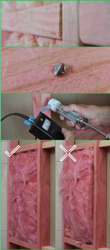
Trouble Shooting Repairs & Maintenance Finishing & Jointing Systems GIB® Performance Systems General Installation Pre-Installation Product Range Introduction
4.1 BEFORE STARTING INSTALLATION
Inspect the framing
Check that the surface is flat and that there is nothing that could affect the finished surface. For example:
Nogs not flush.
Nails not below the framing surface.
Do not simply rely on the building inspector at the preline inspection but take responsibility and understand the effects of framing moisture on content and the quality of finish.
Moisture content to be 18% or less.
Nail plates or hold down ties not checked in flush with the surface insulation bulging out between studs.
These are all factors that will affect the quality of the finished surface. The time to correct them is now. Once fixing commences it indicates an acceptance of the substrate quality.
It is the responsibility of the framing contractor to provide a substrate that allows the plasterboard fixer to effectively install the plasterboard in accordance with the manufacturer’s instructions.
Likewise it is the responsibility of the plasterboard fixer to provide a suitable surface for the plasterboard stopper to effectively carry out the stopping process.
There is no place in the industry for the phrase “The stopper will fix it”.
All trades involved in the process have to take full responsibility for the quality of their workmanship.
Cutting GIB® Plasterboard
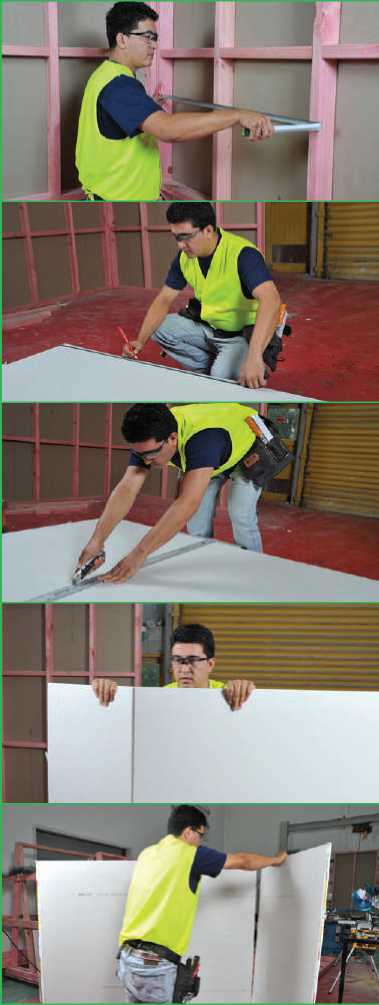
Measure the wall to determine the required sheet size. Generally cut the sheet 2mm–3mm less than the exact dimension needed.
Position the sheet with the face paper side up. Mark the sheet as required.
Firmly hold the straight edge on the line to be cut.
Cut through the face paper and into the plaster core by sliding the knife blade against the straight edge.
Break the sheet core by snapping the sheet back firmly while holding on to the sheet edge.
Turn the sheet over so that back paper is now facing up. Score the back paper to complete the cut.
Cutting GIB® Plasterboard
For sheets requiring multiple cuts, use a handsaw to complete the short cuts before scoring and snapping the longer cut.
Mark the position of any power outlets or pipes on the face of the board.
Make hole at a corner of the marked outlet. Cut out the box as marked.
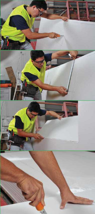 |
Trouble Shooting Repairs & Maintenance Finishing & Jointing Systems GIB® Performance Systems General Installation Pre-Installation Product Range Introduction |
Tip: To get the saw started, drill holes at each of the corners but within the opening. In some cases the saw can simply be pushed through the sheet without the need for holes.
Fixing GIB® Plasterboard
Apply GIBFix® adhesive at specified centres. Apply immediately prior to fixing the GIB® plasterboard. Do not allow time for the adhesive to “skin” over.
GIBFix® adhesive daubs should be approximately 35mm in diameter and about 12mm high.
Cold temperatures (10ºC or less) will affect the curing time of adhesive. It is recommended that steps are taken to achieve 10ºC at the time of installation.
Tip: Do not place GIBFix® adhesive behind fasteners. This will increase the risk of “fastener popping” Place at least 200mm from fasteners
Fit the GIB® plasterboard in position against the framing. Press the sheet firmly against the framing to ensure a good bond with the adhesive.
Sheets must be 5–10mm from the floor. Place packers to suit OR use a flat bar to lift the sheet off the floor.
(Note that some specific fire rated systems require that the sheets are fixed hard to the floor).
Install fasteners at specified centres. Make sure that the head of the fastener is bedded just below the surface of the board.
Tip: Use an electric drywall screwgun equipped with an adjustable depth control head and Philips bit. If a screw is overdriven and the paper and/or core of the GIB® plasterboard is damaged, insert a second screw approximately 50mm from the first and then remove the first screw.
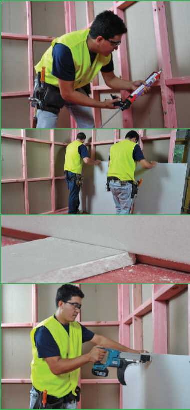
How much GIBFix® adhesive to use?
A simple method of reducing GIBFix® waste and having consistently sized daubs of adhesive is to remove the sealer cap from a sipper type drink bottle top and fit it to the nozzle of an adhesive cartridge. Press the face of the cap against the surface and apply pressure to the adhesive applicator gun. The cap will fill with adhesive and when full, pull the cap away from the surface. This will leave a daub of adhesive approximately 35mm in diameter and with a raised “peak” of about 10–12mm.
|
GIBFix® One GIBFix® AllBond | 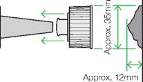 |
Timber Framing
Joint Placement Vertical Fixing
Give careful consideration to the placement of sheet joints in walls and ceilings.
Try to minimise sheet joints by using the largest sheet size available.
Where possible place joints in situations where they are less likely to affected by critical lighting.
Form sheet edge joints in vertically fixed walls on studs.
Shorter vertical joints (400mm or less) such as above a window or door can be made off the stud. Joints under windows can be made off the stud provided that nogs are installed to reduce the unsupported joint to 600mm or less. Alternatively the joint may be back blocked.
Horizontal Fixing
Around Door or Window Openings
Sheet edge joints in horizontally fixed walls may be unsupported (stud centres must not exceed 600mm).
For levels of finish 3 and 4, sheet end butt joints may be made on studs. However, to reduce the risk of joint defects, it is strongly recommended that sheet end butt joints are back blocked off framing.
Sheet edge joints formed at the edge of door and window openings are highly prone to cracking. To reduce the risk of cracking it is strongly recommended that sheets are cut around openings and joints are formed no closer than 200mm to the edge of the opening.
General Installation – Not recommended
General Installation – Not recommended
Prone to cracking due to frame flexibility. Not recommended for general installations.

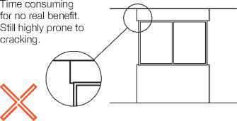
cceptable
General Insta
This moves the joint away from problem area. Floating joint, correctly taped and stopped is less likely to crack.

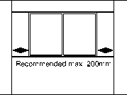
Positioning the jo 200mm from the window edge will reduce the likelihood of cracking.

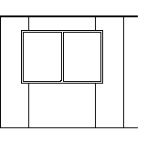
General Installation – Recommended
High Movement Applications
If the grooved jambs have been tl itlld this is not difficult for a competent fixer, The lining on this wall will need to be fixed prior to any adjacent walls,

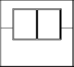
For applications prone to a high degree of movement, such as transportbl homes, consider should be given installing a contr the edges of the window (see p. 4


Control Joint
Trouble Shooting Repairs & Maintenance Finishing & Jointing Systems GIB® Performance Systems General Installation Pre-Installation Product Range Introduction
IK 4.3 GIB® PLASTERBOARD INSTALLATION – WALLS
UId
For installation guidance on GIB EzyBrace® and For all other GIB® Performance Systems refer to
GIB Aqualine® Wet Area Systems refer to the GIB® the relevant GIB® Systems literature.
Performance Systems section.
Wall Framing
— Timber moisture content must not exceed 18% (see p. 30)
Fasteners
|
Installation
Stopping
*Some GIB® Performance Systems may require different fastener lengths and types. Refer to the applicable GIB® System literature for more information. |
Timber Frame – Horizontally Fixed
Fasteners as specified above at 300mm centres to top and bottom plates and perimeter studs
Fasteners to each stud where the horizontal joint crosses the stud
Option A
|
5–10mm gap between bottom edge of lower sheet and floor Fastener placement 50mm in each direction from corner GIBFix® adhesive or fasteners as specified above at 300mm centres Sheets touch fitted | 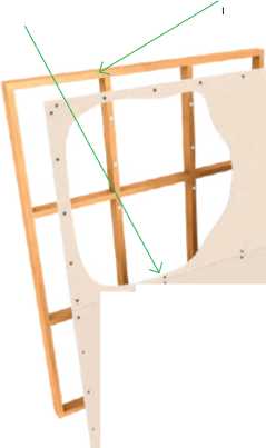 |
|
Option B | |
Studs at 600mm maximum

|
4.3 GIB® PLASTERBOARD INSTALLATION – WALLS For installation guidance on GIB EzyBrace® and For all other GIB® Performance Systems refer to GIB Aqualine® Wet Area Systems refer to the GIB® the relevant GIB® systems literature. Performance Systems section.
Wall Framing
Fasteners
Timber Frame – Vertically Fixed |
Installation
— Place fasteners no closer than 12mm from paper bound sheet edge or 18mm from any cut edge
Stopping
|
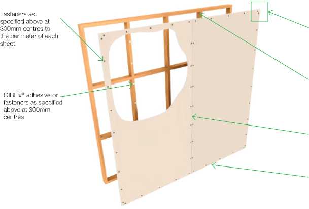
IK 4.3 GIB® PLASTERBOARD INSTALLATION – WALLS
UId
For installation guidance on GIB EzyBrace® and For all other GIB® Performance Systems refer to
GIB Aqualine® Wet Area Systems refer to the GIB® the relevant GIB® systems literature.
Performance Systems section.
Metal framing to which GIB® plasterboard is fixed must be in accordance with AS/NZS 4600 or NASH Standard. The lining thickness for specific design steel framing systems can be determined by the designer as a component in the system. For other light steel framing application a minimum thickness of 13mm GIB® plasterboard shall be used. Wall Framing — Steel stud dimensions to be min. 64 x 34 x 0.50mm nominal with a 6mm return — Steel channel dimensions to be min. 64 x 30 x 0.50mm nominal
Fasteners
|
Installation
— Place fasteners no closer than 12mm from paper bound sheet edge or 18mm from any cut edge — It is recommended that fasteners at wall corners be placed 50mm in from the corner in each direction
— Place daubs of GIBFix® adhesive at 300mm centres to intermediate studs
Stopping
*Some GIB® Performance Systems may require different fastener lengths and types. Refer to the applicable GIB® System literature for more information. |
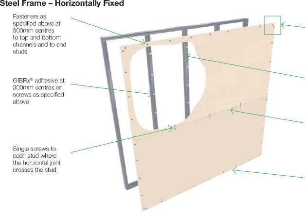 |
Fastener placement 50mm in each direction from corner Studs at 600mm maximum Sheets touch fitted 5–10mm gap between bottom edge of lower sheet and floor |
-
4.3 GIB® PLASTERBOARD INSTALLATION – WALLS
|
For installation guidance on GIB EzyBrace® and For all other GIB® Performance Systems refer to GIB Aqualine® Wet Area Systems refer to the GIB® the relevant GIB® systems literature. Performance Systems section.
Metal framing to which GIB® plasterboard is fixed must be in accordance with AS/NZS 4600 or NASH Standard. The lining thickness for specific design steel framing systems can be determined by the designer as a component in the system. For other light steel framing application a minimum thickness of 13mm GIB® plasterboard must be used. Wall Framing — Minimum steel stud dimensions to be min. 64 x 34 x 0.50mm nominal with a 6mm return — Steel channel dimensions to be min. 64 x 30 x 0.50mm nominal
Fasteners
Steel Frame – Vertically Fixed |
Installation
Stopping
|
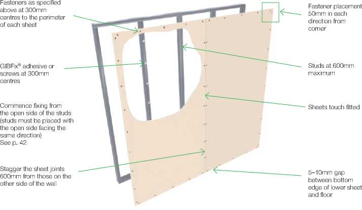
|
«0 GIB
Correct Method As the face of a steel stud can deflect initially, the correct sequence of attaching the plasterboard is important. The first sheet is attached to the open side of the stud which will cause minor deflection but will pull back tight against the sheet when the screw is fully tightened. |
When the second sheet is fixed there will be minimal deflection as the open flange is now supported by the previous sheet. Support the stud to avoid twisting. |
Fastening GIB® Plasterboard to Metal Studs
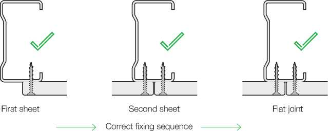
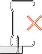 |
|
First sheet |
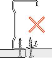


Second sheet Lipped joint
Second sheet Twisted stud
■) Incorrect fixing sequence
Incorrect fixing method can result in lipped joints, twisted studs and misalignment of the wall.
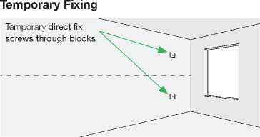
Tip: Occasionally a bow may develop in the board due to storage methods. It might be necessary to temporarily hold the board until the adhesive cures.
Screw through an offcut of plasterboard and remove the block and screw once adhesive has cured.
Winstone Wallboards recommends: The use of architraves for finishing around doors and windows for the following reasons. — Larger plasterboard sheets can be used, resulting in fewer joints.
Architraves make best practice fixing of plasterboard much simpler. If the use of grooved jambs is unavoidable here is some information to help minimise plasterboard fixing problems. Grooved door jambs and window liners are an integral part of the New Zealand building scene. Unfortunately their use means that additional joints often need to be made in the wall surface. Installation of grooved jambs is subject to workmanship skills. Unless the jambs are correctly set up and installed, with a 1–2mm clearance for the plasterboard, it is difficult to install the board effectively. Grooved Jambs and Architraves Summary
— Accurate measuring and ordering by the building contractor — Accurate fabrication by the joinery manufacturer — Careful installation by the installer
|
If the use of grooved jambs is unavoidable there are some golden rules to be followed. The groove must be at least 1–2mm wider than the board that is being used. Trying to get a 10mm plasterboard into a 10mm groove will be difficult. Line the back of the groove up with the face of the substrate. Trouble Shooting Repairs & Maintenance Finishing & Jointing Systems GIB® Performance Systems General Installation Pre-Installation Product Range Introduction
|
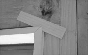
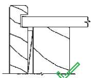
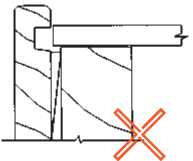
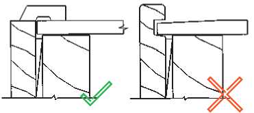
|
«0 4.3.7 Reducing Joints When Using Grooved Jambs GIB
|
|
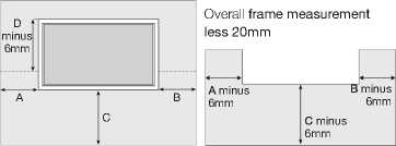
-
4.4 INSTALLATION TO CEILINGS
Truss dimensions and spacings must comply with NZS3604:2011. The use of GIB® Rondo® metal ceiling battens is strongly recommended. Timber battens can be prone to conditions that contribute to joint failure and popped fasteners. If the use of timber ceiling battens is unavoidable, additional care needs to be taken to ensure that the moisture content is 18% or less (see p. 30). To limit sag in GIB® plasterboard ceilings, long term uniformly distributed loads such as that of fixtures and fittings and/or overlaid insulation shall not exceed 3kg/m2 unless independently supported |
Winstone Wallboards recommends:
|
|
General Ceiling Installation |
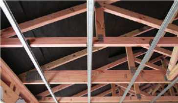 |

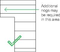
-
4.4.2 Standard Ceiling Fixing
This information applies to the general installation of GIB® plasterboard. If bracing, fire or noise control is a consideration consult the relevant GIB® Systems literature.
Ceiling Framing
-
— If using timber ceiling battens, timber moisture content must not exceed 18% prior to lining (see p. 30)
-
— Battens should all run in the same direction within a ceiling area. Additional nogs may be required to achieve this
Batten Spacing
-
— 10mm GIB® plasterboard – 450mm maximum — 13mm GIB® plasterboard – 600mm maximum — Winstone Wallboards recommends the
use of 13mm GIB® plasterboard in ceiling applications for optimal performance
Fasteners
Metal Battens
-
— Minimum 25mm x 6g GIB® Grabber® fine thread self tapping screws*
Timber Battens
-
— Minimum 32mm x 6g GIB® Grabber® high thread screws*
Fastener Spacings
-
— Single screws at the edges and centre of the sheet across the batten
-
— Single screw at 600mm maximum to the perimeter of the ceiling. See p. 68 for ceiling diaphragm installation
-
— Place fasteners no closer than 12mm from a taper sheet edge or 18mm from a cut sheet edge
Adhesive
-
— Place daubs of GIBFix® adhesive at 200mm to intermediaries
-
— Do not place adhesive at sheet edges or within 200mm of fasteners
Lining
-
— Sheets should be touch fitted
-
— Sheets must be fixed at right angles to the ceiling framing unless otherwise specified in GIB® Performance System specifications
Stopping
-
— Refer to the Joint and Finishing section (p.78)
*Some GIB® Performance Systems may require different fastener lengths and types. Refer to the applicable GIB® System literature for more information
Ceilings
1 x GIB® Grabber® screw to sheet edge at each batten intersection
GIB® Rondo® batten and clip
Back-block sheet end joints
Stagger sheet end joints by minimum 600mm
(600mm for 13mm GIB® plasterboard, 450mm for 10mm GIB® plasterboard)
GIBFix® adhesive
1 x GIB® Grabber® screw to sheet centre at each batten intersection
Sheet edge back blocks (see to p. 47)
Trouble Shooting Repairs & Maintenance Finishing & Jointing Systems GIB® Performance Systems General Installation Pre-Installation Product Range Introduction
|
gib 4.4.3 Raking Ceilings and Skillion Roofs Due to the higher temperatures and low air movement that can occur in raking ceilings it is strongly recommended that clip fixed GIB® Rondo® metal battens are used (these are considered to be ceiling suspension systems). Because of the heat that can be generated in roof spaces, timber battens can be subjected to conditions that contribute to joint failure and popped fasteners. |
The use of control joints or perimeter relief will help reduce the risk of cracking in large, expansive ceilings. These may not be suitable for use in Fire or Noise Control Systems. Back blocking of all ceiling joints is highly recommended as it can reduce the likelihood of cracking.
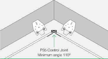
|
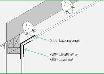
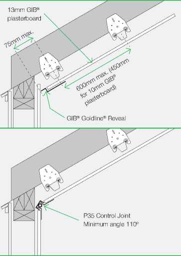
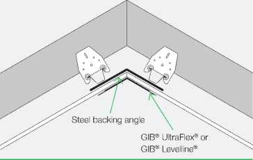
Back blocking is the practice of laminating an off-cut of plasterboard to the back of a joint using GIB-Cove® Bond adhesive. Back blocking is required to ceiling sheet edge joints as follows: Timber Battens When there are 3 or more tapered edge joints in a ceiling area Metal Battens When there are 6 or more tapered edge joints in a ceiling area Back blocking is required to all joints when a Level 5 Finish has been specified. Back blocking is strongly recommended at sheet end joints in ceilings. Some fire rated systems require that joints are made on solid blocking and that requirement takes precedence and must be followed. Refer to GIB® Fire Rated Systems specifications for more information. Back blocking is not required for a Level 4 Finish when a suspension system has been used. This includes GIB® Rondo® metal ceiling batten system fixed on clips. See p. 46. Sheets ends should be back blocked. Due to wind pressure when garage door is open, and vibration from garage door opening, it is recommended that all sheet joints in garage ceilings are back blocked.
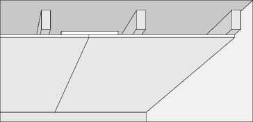
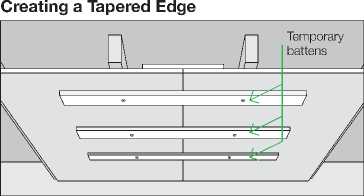

|
Back Blocking Comprises 2 Steps:
Step 2 can be omitted but the stopped joint will need to be much wider (500–600mm) in order to minimise the effect of the stopping joint thickness. Back Blocking Technique — Make back blocks at least 300mm wide and cut to fit loosely between framing members
the tapered lock
of the bac ng the next she Trouble Shooting Repairs & Maintenance Finishing & Jointing Systems GIB® Performance Systems General Installation Pre-Installation Product Range Introduction |
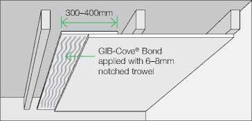
|
gib 4.4.5 Control Joints – Walls and Ceilings These control joints and maximum recommended centres aim to provide relief from stresses associated with changes in temperature, humidity and the response of dissimilar construction materials (e.g. metal, timber, gypsum and plasterboard). For more significant structural movements consult the building designer. Walls
Ceilings
Other situations
|
Perimeter relief using GIB® Goldline® Tape-On Trims 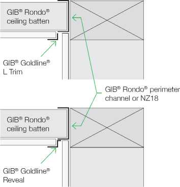 |
Control Joints in Ceilings – Recommendation to Reduce Risk of Cracking
There are some common places within the 12m spacing where cracks are most likely to occur in ceilings (as shown below).
It is recommended to consider installing control joints in these locations (as shown below) to reduce the risk of cracking.
|
Where hallways exit from a larger ceiling area. At internal corners in irregular shaped ceilings or where the main ceiling would look better divided into smaller sections. |
At openings such as skylights, voids or recessed strip lighting. This may also include designated functional areas of a space. |
|
Plan view Plan view |
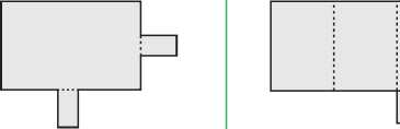 |
|
Plan view |
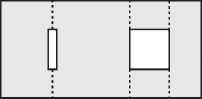 |
-
4 .4.5 Control Joints – Walls and Ceilings Installation of the GIB® Rondo® P35 control joint
-
— Allow an 18mm minimum gap between the plasterboard sheets
-
— Locate the GIB® Rondo® P35 control joint centrally in the gap. Staple both flanges to the lining at 150mm centres maximum
-
— Finish with jointing compound using the channel nibs as screeding guides
-
— When the joint is dry remove the protective tape
Control joint using GIB® Goldline®
Platinum trim
-
— Allow a 14–17mm gap between the plasterboard sheets
-
— Install GIB® Goldline® Platinum GR reveal to one side of joint
-
— Install GIB® Goldline® L Trim to the other side. Use a spacer to provide an even gap between the trim. This can be between 3–12mm
-
— Apply compounds as described on p. 83–84
GIB® Plastic W-profile Control Joint
-
— Discrete finish and has tear-away tabs for easy installation
-
— This trim is thicker than the other control joint trims and thus may have implications for the final joint height
-
— Available in 3.0m lengths
Note: Contact the GIB® Helpline 0800 100 442 for detailing of control joints in GIB® Performance Systems (e.g. fire, noise, bracing).
Installation of the Rondo® P35 control joint 1.
min. 18mm gap
K------->1
f Jfc|L I
K----------------------------X
70mm
Control joint using GB® Gldline® Platinum trim 2.
14mm–17mm
13mm GR Reveal


GIB® Goldline® G4 10mm L-Trim
GIB® Plastic W-profile Control Joint
3.
16mm–18mm
K------>1
Trouble Shooting Repairs & Maintenance Finishing & Jointing Systems GIB® Performance Systems General Installation Pre-Installation Product Range Introduction
«0
GIB
|
GIB® Rondo® Steel Battens |  |
Timber Stud Walls

Stud

£
GIB® Rondo® P35 Control Joint
|
150mm max |
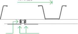 |
|
18mm gap between sheets |
GIB® Rondo® P35
Control Joint
18mm gap between sheets


GIB® Goldline® Platinum Trim
14mm–17mm gap between sheets
|
Two Storey Full Height Wall with Expansion Joint |
Masonry Junction Timber or Steel Framing
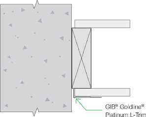
|

|
4.4.6 GIB® Rondo® 310 Metal Batten System Installation Instructions The GIB® Rondo® 310 system forms a strong, stable and flat substrate for ceilings in residential and commercial applications. The 35mm dimension allows it to be directly substituted into ceilings where 35mm timber battens would traditionally have been used. Consult an electrical contractor for any earthing requirements that may need to be incorporated. There are two methods of fixing GIB® Rondo® 310 metal battens. Recommended method Clipped using either: 311D clip for a drop of 0–30mm 313 clip where a larger drop is required between the bottom of the truss chord, joist or rafter and the back of the ceiling batten
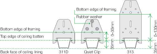
|
A drop of up to 130mm can be achieved in order to accommodate services or variations in framing heights
Alternative method
Note: If the 310 system is to be used in a ceiling diaphragm the batten needs to be screwed directly through the flanges to the framing. Trouble Shooting Repairs & Maintenance Finishing & Jointing Systems GIB® Performance Systems General Installation Pre-Installation Product Range Introduction |
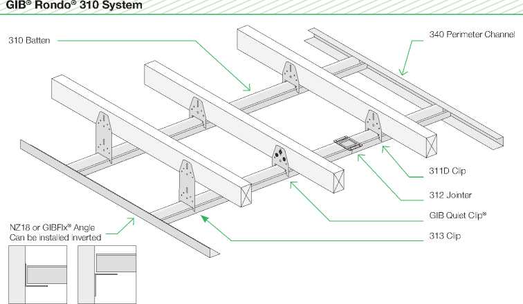
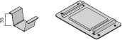
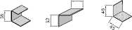
-
4.4.6 GIB® Rondo® 310 Metal Batten System Installation Instructions
|
GIB® Rondo® 310 System Recommended Best Practice Details Other Details |
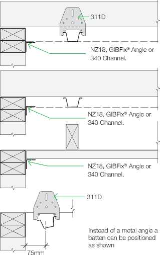 |
|
max. |
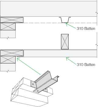
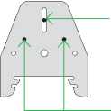 |
Insert one 32 x GIB® Wafer Head screw into the vertical slot firmly but not quite home. Adjust levels as required and then drive completely home Insert 2 further fasteners to complete the connection |
|
Cut the batten to the required length using snips or a hacksaw Insert the batten into the channel at each end and fit into the clip Install remainder of clips ensuring that the batten is straight and flat |
GIB® Rondo® 310 Batten Span Table for Residential Internal Applications
Battens
|
GIB® Plasterboard Thickness – Single layer |
10mm |
13mm |
|
Maximum Batten Spacing (mm) |
450 |
600 |
|
Multi Span (mm) |
1200 | |
|
Single Span and Garages (mm) |
900 | |

-
4.4.7 GIB® Rondo® 308 Metal Batten System Installation Instructions
|
The GIB® Rondo® 308 system is a light weight yet very strong ceiling batten. In addition to its function as a ceiling batten it can also be used as a wall furring channel and is an integral part of GIB Noise Control® Systems for walls. Consult an electrical contractor for any earthing requirements that may need to be incorporated. GIB® Rondo® 308 System
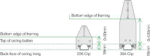
|
Recommended method The GIB® Rondo® 308 system is installed using either:
Up to 130mm clearance between the bottom of the framing and the back of the batten of can be achieved in order to accommodate services or variations in framing heights Note: If the 308 system is to be used in a ceiling diaphragm, the batten needs to secured directly to the framing (see p. 69). Trouble Shooting Repairs & Maintenance Finishing & Jointing Systems GIB® Performance Systems General Installation Pre-Installation Product Range Introduction |
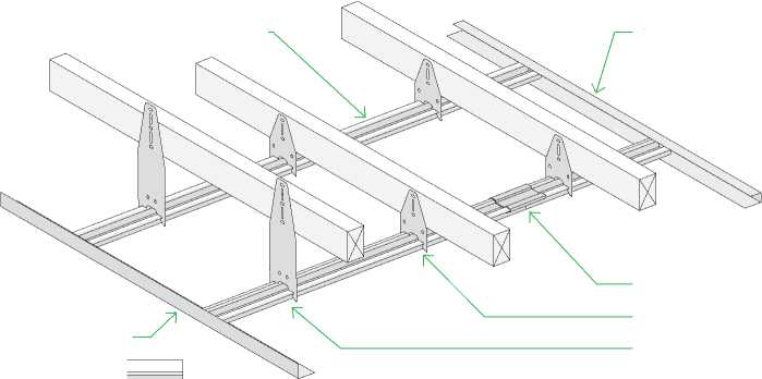
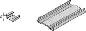
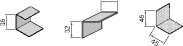
«0
-
4.4.7 GIB® Rondo® 308 Metal Batten System Installation Instructions
GIB® Rondo® 308 System
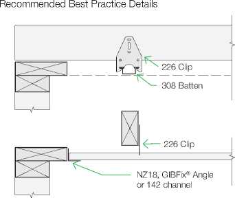
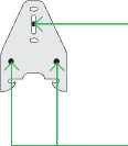 |
Insert one 32 x 8 GIB® Wafer Head screw into the vertical slot firmly but not quite home. Adjust levels as required and then drive completely home Insert 2 further fasteners to complete the connection |
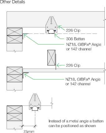 |
|
max. |
|
Establish a datum line for the ceiling Place a string line on the datum line at right angles to the battens, under the truss or joist closest to the centre of the room Install GIB® Rondo® clips at 600mm centres (450mm for 10mm GIB® plasterboard) using the string line to establish the correct position GIB® Rondo® 308 Batten Span Table for Residential Internal Applications |
Cut the batten to the required length using snips or a hacksaw Insert the batten into the channel at each end and fit into the clip Install remainder of clips ensuring that the batten is straight and flat Battens 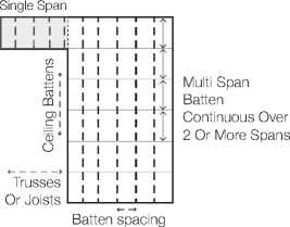
| ||||||||||||
|
This is not to be confused with a two way grid system which accommodates proprietary ceiling tiles. The components can be assembled in a wide range of combinations to suit a variety of applications. Refer to GIB® Rondo® System literature for more information. GIB Trouble Shooting Repairs & Maintenance Finishing & Jointing Systems GIB® Performance Systems General Installation Pre-Installation Product Range Introduction | |||||||
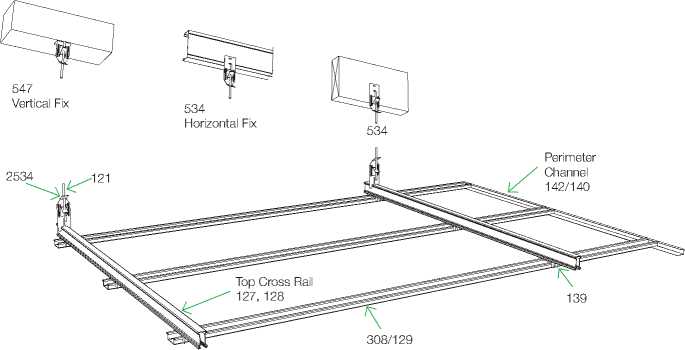
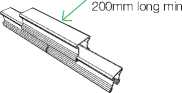
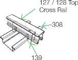
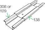
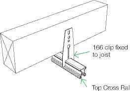
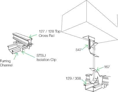
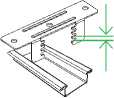
|
IK 4.5 CURVING GIB® PLASTERBOARD UId GIB® plasterboard can be curved. Curvature is dependent on the thickness and type of board and whether the board is applied wet or dry. Sheets must be fixed horizontally to walls. The radii shown are for GIB® Standard and GIB Ultraline®. Other performance boards such as |
GIB Fyreline® and GIB Aqualine® can also be curved but with slightly increased radii due to the increased density of the board. It is not recommended to curve high density boards such as GIB Braceline / GIB Noiseline® or GIB Toughline® due to the risk of breakage.
Application Method
Note: Lining the inside of the curve will be more difficult than lining the outside and will require additional labour. 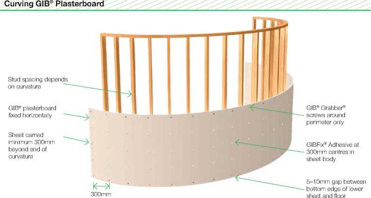
|
Direct bonding of GIB® plasterboard to concrete or brick masonry walls must only be considered when the concrete or masonry substrate is thoroughly dry and adequately protected against moisture penetration. The substrate must be firm, dry, and free of dust, grease, release agents and curing compounds. Direct Bonding (For Sheet Heights up to 3m)
Ensure that adhesive is placed no closer than 25mm from the edge of the sheet
Wall Strapping must be used:
or metal furring channels. Deeper strapping may be required to accommodate insulation requirements
|
In situations where dampness or rain penetration problems exist, corrective measures must be taken prior to installation of interior linings. Movement and control joints in the main structure must be carried through the GIB® plasterboard linings. This can be achieved by installing a control joint in the plasterboard. Daubs approximately 50mm diam. x 12mm high Daubs placed no closer than 25mm from sheet edge Control joints in walls need to continue through GIB® plasterboard
50 x 25mm KDMG timber or GIB® Rondo® Steel Battens, maximum 600mm apart. Pack battens as required to provide a flat surface Trouble Shooting Repairs & Maintenance Finishing & Jointing Systems GIB® Performance Systems General Installation Pre-Installation Product Range Introduction
|
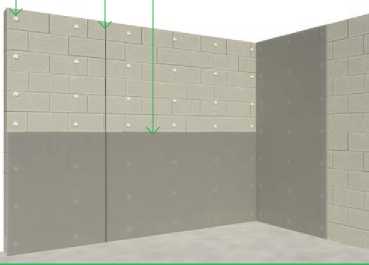
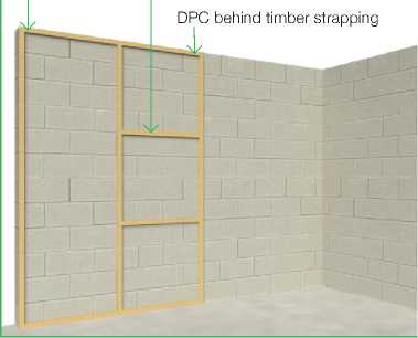
|
IK 4.6 FIXING TO MASONRY UId If insulation is required to concrete or masonry, it is recommended that GIB® Rondo® 308 battens are clipped to GIB® Rondo® A239 clips as |
shown. A239 clips should be spaced at 1200mm centres (maximum) vertically and 600mm centres (maximum) horizontally. |
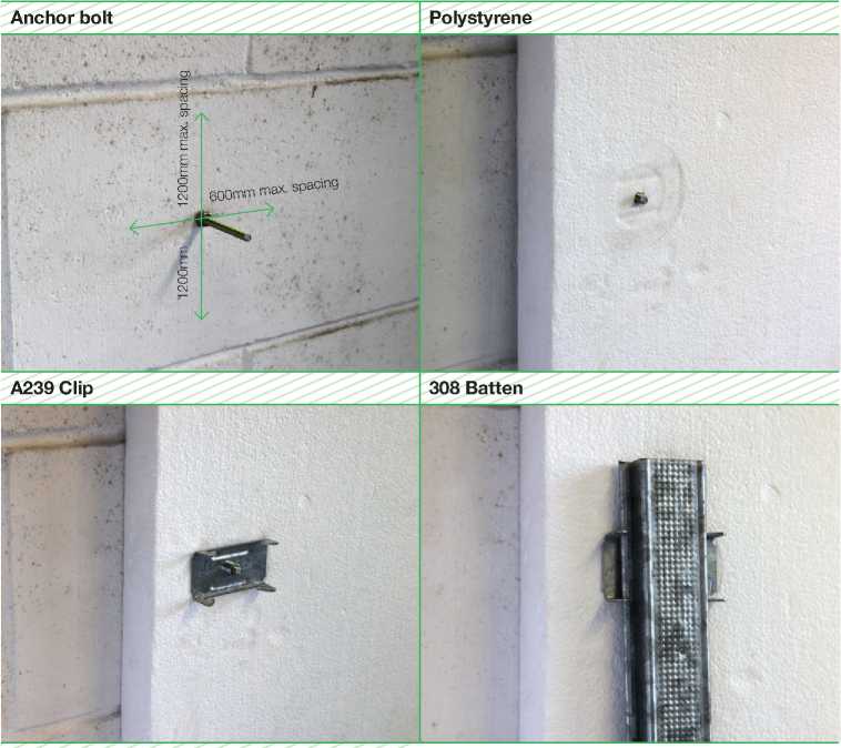
A239 Clip 308 Batten Anchor bolt Polystyrene |
|
GIB® Plasterboard overlay |
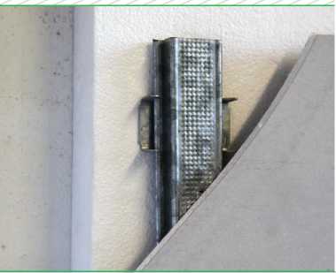 |
ALUMINIUM
ECLIPSE ALUMINIUM SUITE
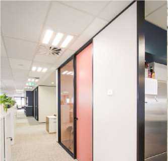
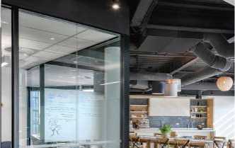

PRODUCT SUMMARY
The Eclipse Aluminium Partition Suite is a quality, user-friendly group of flexible Aluminium sections and extrusions. Its complete system caters for nearly any variable in an interior office fit-out.
This versatile suite has been designed to work with 64mm and 92mm stud sizes respectively and can be clad with 13mm plasterboard. A separate 45mm suite can be added as a slim-line extension to the 64mm and 92mm sections or can be installed separately as a minimalistic and cost effective alternative.
The Elipse Aluminium Suite has been acoustically tested for STC performance and the results reflect actual performance as a complete system. The double glazed partition is able to reach an STC performance of 47dB.
The suite is available in a range of colours and finishes; 500+ Resene and Dulux powdercoat colours, 15 MetWood finishes, bespoke and others available upon request. An antimicrobial coating can be applied for when used in hygiene and medical spaces. The standard anodised colour is silver.
The suite has great adaptability to meet most functionality and aesthetic purposes. Furthermore, since the product is manufactured in New Zealand, bespoke options are available.
METWOOD FINISHES:
|
•••••••• Black Bean Darkest Gum Dark Riverwood Washed Riverwood Plywood Washed Teak Honey Manuka Oak Broom |
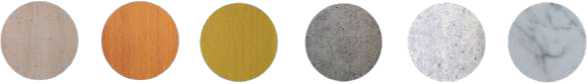 |
|
Beachwood Tawa Kahikatea Concrete White Concrete Grey Marble White Marble |
ECLIPSE ALUMINIUM SUITE
ALUMINIUM
ECLIPSE 45MM ALUMINIUM PARTITIONING SUITE
Designed to work in isolation or in conjunction with the Eclipse 64mm, the Eclipse 45mm offers a fine-line design with soft detailing. Again the pocket glazing and snap fix componentry enhances the user friendly nature of the suite, whilst ensuring high aesthetic appeal with the completed installation.
ECLIPSE 45MM FRONTLINE ALUMINUM PARTITIONING SUITE
A new take on the existing 45mm suite, to add a frontline glazing option for the slimline look.
ECLIPSE 64MM ALUMINIUM PARTITIONING SUITE
This has been primarily designed around 64mm steel stud to incorporate up to four layers of 13mm Gypsum Plasterboard.
The J Mould has been added to the suite to enhance the flexibility and to assist with the trimming off of strapped walls and bulkheads etc. The Eclipse 64mm Aluminium Partitioning Suite offers immense flexibility incorporating pocket glazing and snap fix componentry together with detailing to incorporate the Eclipse 45mm as required.
ECLIPSE 64MM FRONTLINE ALUMINIUM PARTITIONING SUITE
A frontline glazing addition to the comprehensive 64mm suite, provides an added ability to double glaze for acoustically sensitive areas.
ECLIPSE DOOR SUITE
A comprehensive door suite in 100mm, 120mm and 80mm options. This suite has the ability to offer top hung sliding doors, bottom rolled sliding doors and hinged doors. The glazing pocket allows for thicker acoustic glass and the doors will accommodate acoustic seals for improved privacy. Acoustic doors are available where required.
The Eclipse Aluminium Suite poster, brochure, Revit and DWG files are available for download from the T&R Interior Systems website; tris.co.nz
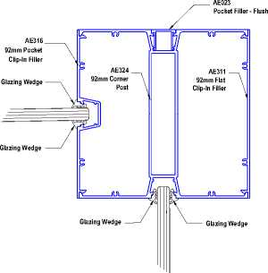
|
O INT&RIOR SYSTEMS Guiding Design Informed Interiors Eclipse Aluminium Partitioning Suite 0800 666 556 www.tris.co.nz Wellington, Auckland, Christchurch Stick-on Door Suite 45mm 45mm Suite VertiBrace Glazing Pocket Fillers Slipper Glazing Mullions Frontline Plates 19.10 19 19 AE023 AE018 AE023 AE405 FlatSlipperPlate AE406 AcouticSlipperPlate (uses2xSeal) AE018 64mmClip-InDoorSto ((uupsetso5Se0aml)m 19.1 19.7 |
Bead —^ 120mm 120mm DoorStop E005/B G2l/a6z4i/n4g5mBemadBra GlazingBead 64mm Frontline & Double Glazing GlazingBe WShape(carpet) BShape(hardfloors) 64mm Suite TrEu5n0k3iLng95Li 45mmFrontline GlazingBead E002/45 Stick-On GlazingMullio E402/120 AE011 64mmFlat Clip-InFiller AE400/120 AE009/100 E415 nternalDoo GMuiilldeOAnldy)aptor AE416 SlidingDoor Pick-Up AE011/R 64mmRebate Clip-InFiller 132 A9P2Eom0ck3me2-tF9rH2oenatdlitrnaecGklazing |
|
Climp-ImnPFoillcekre 92mmSnap-In 92mmRebated lip-InFiller Jointer Clip-InFiller |
® AE318 AE317
92mmClip-In DoorStop 92mmClip-InDoorStop
ABiE-4F1o7ldDoorStop ((uupsetosS50eaml)mDoors) (upto40mmDoors)
((uupsetso4S0eaml)mD
GlazingBead
AE407
(AucsoeussSticealS)ideSlipperPlate
92mm Frontline & Double Glazing
AE011/D 64mmSnap-In Jointer
PHONIC DIRECT FIX
High Performance Acoustic Ceiling Tile
PHONIC
ACOUSTIC CEILING TILES
 |
High Absorption Glasswool |
 |
Hygrothermal |
 |
Hygiene |
 |
Fire Test- Group 1S |
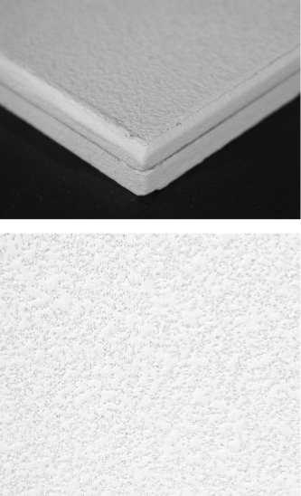
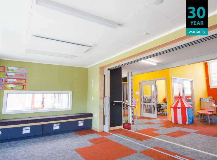
PRODUCT SUMMARY
Phonic Direct Fix is a white painted, textured glasswool acoustic ceiling tile. Direct Fix eliminates the need for an exposed grid and enhances the clean smooth monolithic surface.
-
• It has a high noise reduction coefficient (NRC 0.75 - 1.00 depending on installation method) to reduce reverberation time. A high end tile.
-
• Designed for direct fix application to new existing gypsum board or over timber/metal battens. The Direct Fix 20mm tile on batten exceeds Department of Education acoustic requirements when installed over gypsum board backing.
-
• Tested to the principal requirements in accordance 14644.1:2015 and ISO 14644.3:2015 and the tile meets Cleanroom ISO Class 3.
-
• This product is constructed from 90% dry felt resin bonded glass-wool, utilizing longer fibres in a compact fibre arrangement. The non-absorbent, non-water soluble design gives Phonic Direct Fix improved durability when compared to mineral fibre.
-
• Phonic Direct Fix achieves a density of 100kg/m3. This results in a lightweight, high performance ceiling tile which is user friendly and ideal for use in classrooms, offices, medical centres, lobbies and receptions and other commercial interiors.
30 year lifetime system warranty to withstand conditions up to 40°- 99% relative humidity without visible sag.
EMISSIONS, SUSTAINABILITY AND THE ENVIRONMENT
For Green Star rated projects, Phonic meets the Greenguard Emission Certificate standard.
PHONIC
ACOUSTIC CEILING TILES
PHONIC DIRECT FIX s
High Performance Acoustic Ceiling Tile 0W
GENERAL TEST DESCRIPTION RESULT TEST METHOD
| ||||||||||||||||||||||||||||||||||||||||||||||||||||||||||||||||||||||||||||||||||||||||||||||||
|
Acoustic Performance re-tested in New Zealand labs in 2019. Please note; these results may differ from earlier datasheets | ||||||||||||||||||||||||||||||||||||||||||||||||||||||||||||||||||||||||||||||||||||||||||||||||
INGREDIENTS
Fibreglass tissue face with acrylic resin (back and front of tile) 7-10% - Fibreglass (Glasswool) 80-85%, Acrylic resin 15-20%, Acoustic board 70-80% - Glasswool 88-89%, Phenolic resin 11-12%, Water-based paint 20-25% - Acrylic emulsion 10-15%, Inorganic filler (Kaolin, Calcium carbonate) 40-55%, Environmentally friendly flame retardant 15-25%, A variety of additives (Dispersant, Leveling agent; from Polycarboxylate ammonium salt, EGBE-Ethylene glycol monobutyl ether, Water) 3-5%, Ion water 15-20%, Glue 2-4% - Acrylic resin 50-55%, Ion water 45-50%.

PHONIC
ACOUSTIC CEILING TILES
INSTALLATION GUIDE
PHONIC DIRECT FIX FREE-FLOATING
STEP ONE
STEP THREE
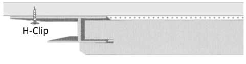 |
Plasterboard Phonic Direct Fix tile |
STEP FOUR
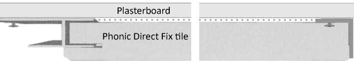 |
Aluminium Angle |
ALTERNATIVE
] 29mm4
Furrning Channel at 300mm centres
Plasterboard
Phonic Direct Fix tile
 |
Perimeter Channel |
|
] 19mm4 | |
STEP ONE
Determine tile configuration and identify fixing points for the H Clips on the ceiling. The layout is dependent on the desired configuration. Leave the edges free.
Please note that whatever the configuration, the final tile will have a maximum of one edge with H clips.
STEP TWO
Install an aluminium angle along the edges to create a frame
STEP THREE
Apply adhesive to the back of the tiles and place the tiles into the aluminium frame. Complete one row at a time and use H Clips to mechnically fix the edges as identified in step 1. All tiles with edges on the perimeter should be propped while the adhesive dries.
STEP FOUR
Apply adhesive and slide the final tile into place. Prop until adhesive is dry.
ZENTHE
Wall Dividers & Screens
Technical Data Sheet
Smart customisable wall divider and screen system
|
New Zealand |
website |
Address |
|
06 842 0004 |
zenthe.co |
8 Cooper Street Havelock North, 4130 |
|
Australia 1800 958 382 |
|
New Zealand |
Technical Information
General Information
|
Zenthe common name Wall Dividers & Screens Key Features + Group 1S fire ratings + Customisable batten spacings and batten sizes + Responsibly sourced options available Typical applications Interior wall divider or screen |
Option one Solid Timber Battens Finished solid timber 10-year product warranty Option Two FR MDF/Timber Veneer Battens. Pressed timber veneer finish. A large choice of timber veneers available. 5-year product warranty |
Typical Physical Properties
Typical batten size
90mm x 45mm for both options. Fabricated to the height required.
NRC Rating
Please note that these NRC values are based on the battens being installed with 25mm acoustic panel between each batten. NRC 0.60>
Group Fire rating
NZ: 1S (Solid timber with intumescent coating)
NZ: 1S (FR MDF / Timber Veneer)
AUS: 2 (FR MDF / Timber Veneer)
|
Environmental Properties Green Building rating compliance View the EnviroSpec Summary Sheet |
responsibly sourced Available with: FSC® Chain of Custody PEFC™ Certification Ask for our FSC® / PEFC™ certified products |
Installation methods
|
Refer to website for details |
 |
System 1
System 2
System 3
Solid Timber Species
 |
|
Southland Beech New Zealand |
 |
|
Victorian Ash Australia PEFC® |
 |
|
American White Ash North America |
r
Yellow Cedar
Canada
FSC® / PEFC®
 |
|
American Maple North America |
|
FSC® |
 |
|
European Beech Central Europe |
 |
|
American White Oak North America |
 |
|
European White Oak Central Europe |
 |
|
Radiata Pine New Zealand |
 |
|
Tawa New Zealand |
|
FSC® |
 |
|
American Cherry North America |
|
FSC® |
 |
|
Spotted Gum Australia PEFC® |
 |
|
Western Red Cedar North America FSC® / PEFC® |
|
FSC® |
 |
|
Malaysian Kauri Oceania |
 |
|
Matai New Zealand |
 |
|
Rosewood South-East Asia |
 |
|
Saligna Australia |
 |
|
Rimu New Zealand |
 |
|
Iroko West Africa |
 |
|
Sapele West Africa |
FSC®
FSC®
Solid Timber Species
i 1 Illi
Kwila
American Walnut
North America
Australian Blackwood
Australia
PEFC®
Bubinga
Africa
Jarrah
Australia PEFC®
South-East Asia
|
FSC® |
 |
|
Western Hemlock Canada |
Timber Veneer Species
 |
|
Hoop Pine Australia |
 |
|
White Ash North America |
 |
|
Tawa New Zealand |
 |
|
Tasmanian Oak Australia |
 |
|
American Red Oak North America |
|
FSC® |
 |
|
American White Oak North America |
|
FSC® |
 |
|
European Beech Europe |
|
FSC® |
 |
|
Queensland Maple Australia |
 |
|
Silver Beech New Zealand |
 |
|
Brush Box Australia |
|
FSC® |
 |
|
Tasmanian Blackwood Australia PEFC® |
|
FSC® |
 |
|
Black Butt Australia |
|
FSC® |
 |
|
American Walnut North America |
 |
|
Coloured Rimu New Zealand |
 |
|
Totara New Zealand |
|
FSC® |
 |
|
Red Cedar North America FSC® |
|
FSC® |
 |
|
Jarrah Australia PEFC® |
 |
|
Heart Rimu New Zealand |
 |
|
Smoked Oak Engineered from American White Oak |
FSC®
Other veneer options available on request
Sustainability
Zenthe carries Chain of Custody (CoC) certification that enables us to sell Timber, MDF, Plywood and Timber Veneer that carries either FSC® certification or PEFC™ certification.
FSC® certified timber and PEFC™ certified timber undergo independent, third-party audited certification procedures at every step of the supply chain. This provides designers, specifiers, architects, and consumers absolute assurance that those forest and wood products labelled as FSC® certified or PEFC™ certified originate from responsible sources, which are managed to be prescribed social, economic, and environmental standards.

 |
|
The mark of responsible forestry |

Zenthe Solid Timber battens are a natural product and has knots and blemishes in the timber. There will be different colour & grain variations from batch to batch. All timber needs to be handled with care and by qualified tradesmen. Battens need to be stored inside, out of sunlight, off the ground, in a dry moisture free environment and flat, well supported and totally free of moisture with a cover sheet on the top for protection. Zenthe take no reasonability for bowed battens due to incorrect storage and moisture ingress. Zenthe needs to be advised of any complaints within 3 days of received the goods. Any complaints received after 3 days will be void.
ZENTHE
Leaders in interior decorative, acoustic, fire safe Panel and Batten systems.
zenthe.co
Latest update: 2010-09-11
^Tarkett
COMMERCIAL
iQ Optima
Technical Data
VINYL
|
Type of flooring |
EN 649 |
Homogeneous vinyl flooring |
|
CE certification |
Yes | |
|
Classification |
EN 685 |
Commercial: 34 Industrial: 43 |
|
Wear layer thickness |
EN 429 |
2,0 mm |
|
iQ PUR |
Yes | |
|
Total thickness |
EN 428 |
2,0 mm |
|
Total weight/m² |
EN 430 |
2800 g |
|
Dimensional stability |
EN 434 |
≤ 0,40 % for rolls ≤ 0,25 % for tiles |
|
Abrasion Thickness loss Volume loss |
EN 660:Part 1 EN 660:Part 2 |
Group P: ≤ 0,15 mm Group P: ≤ 4,00 mm³ |
|
Residual indentation |
EN 433 |
Approx. 0,03 mm |
|
Castor chair test |
EN 425 |
Suitable |
|
Static electrical charge |
EN 1815 |
< 2 kV |
|
Underfloor heating |
Suitable – max. 27ºC | |
|
Thermal resistance |
EN 12667/DIN 52612 |
Approx. 0,01 m² K/W |
|
Reaction to fire |
EN 13501-1 EN ISO 9239-1 EN ISO 11925-2 |
Class Bfl s1 ≥ 8 kW/m² Pass |
|
Light fastness |
EN ISO 105-B02 |
≥ level 6 |
|
Chemical resistance |
EN 423 |
Good resistance |
|
Bacteria resistance |
ISO 846:Part C |
Does not favour growth |
|
Clean room test |
ASTM F51/00 |
Class A |
|
Slip resistance |
DIN 51130 EN 13893 |
R9 ≥ 0,3 |
|
Colours |
30 | |
|
Form of delivery |
EN 426 Sheet (rolls) EN 427 Tiles (box) |
Approx. 25 r m x 200 cm art. no. 3242_ _ _ 3 digit colour number 61,0 x 61,0 cm 14 tiles/box=5,21 m² art. no. 3217_ _ _ 3 digit colour number |

DATA SHEET
Greenpad – Gold Coast
issue 10/16
Carpet Plank Module pg 1/2
Distributor/Manufacturer
Advance Flooring Systems Limited/Voxflor.
Trade Name
Greenpad – Gold Coast.
Product Description
DuPontTM Sorona® Yarn Dyed & Solution Dyed fibre carpet plank tiles with a PVC or Mix-BacTM backing system.
Product Benefit
Greenpad Gold Coast is a sustainably manufactured carpet module with superior stain resistance providing you a highly durable carpet tile that is easy to clean.
Area of Application
Gold Coast is suitable for use in any high traffic commercial areas.
Composition
Gold Coast carpet modules are made with a graphic tufted multi-level loop construction consisting of 100% renewable DuPontTM Sorona® fibre, bonded to a fiberglass reinforced PVC or Mix-BacTM backing system.
Dimensions
Pile height 4mm + 0.5mm at 21 OZ/yd2
Tile size 250 x 1000mm
Pattern & Colours
Graphic tufted multi-level loop pattern available in a range of 6 colours.
Manufacture
Gold Coast carpet modules are manufactured in China, by Voxflor using manufacturing processes that is ISO 14001:2004 compliant for its Environmental Management Systems.
Smoke/Fire
Gold Coast carpet plank modules comply by exceeding the NZ requirements.
Electrical Resistance
Gold Coast carpet plank modules comply by exceeding the NZ requirements.
Durability
Class 3, Extra Heavy Commercial.
 |
|
Advance SYSTEMS FLOORING |
Advance Flooring Systems Ltd
email: info@advanceflooringsystems.com
www.advanceflooringsystems.com
DATA SHEET issue 10/16
Greenpad - Gold Coast Carpet Plank Modules pg 2/2
Sound Absorption
Voxflor carpet modules with Mix-BacTM backing systems can reduce reverbative noise in a commercial office environment.
UV Resistance
Some fading may be observed in areas of intense sunlight.
Sustainability
Voxflor is committed to the protection of the environment and all products are manufactured to strict ISO 14001: 2004 standards. All Voxflor Greenpad carpet tiles with PVC and Mix-BacTM backing systems are accredited by Environmental Choice New Zealand – licence number 3314129
Installation
Gold Coast carpet modules must be installed by a competent and experienced carpet installer and we recommend the full stick method - more information on the recommended installation procedures is available on our website www.advanceflooringsystems.com or upon request.
We recommend the following installation method for Gold Coast
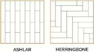
Recommended Adhesive
Strongbond 65 – Look Floors, or Polymer 999 PS – Gilt Edge Industries.
Cleaning and Maintenance
Proper maintenance is one of the most important factors to ensure good performance of carpet. Gold Coast should be vacuumed daily. In the first instance, we believe a good entrance matting system installed at entry areas will help collect up to 90% soiling before it is tracked into the interior of the building - more information on the recommended maintenance procedures is available on our website www.advanceflooringsystems.com or upon request.
Warranty
The manufacturer provides a Fifteen (15) year limited warranty for castor chairs, delamination and dimensional stability, a lifetime stain, soil and antistatic limited warranty and a 25-year fade resistance, abrasive wear limited warranty.
Advance Flooring Systems Ltd
email: info@advanceflooringsystems.com
Advance
SYSTEMS
www.advanceflooringsystems.com

DATA SHEET
issue 04/17
EverTread Entrance System pg 1/2
Manufacturer
Advance Flooring Systems Limited
Trade Name
EverTread
Product Description
An 17mm deep aluminium strip mat system with polyamide inserts for entrance areas.
Product Benefit
EverTread is an entrance mat system engineered to trap soiling and moisture that is easy to clean and protects flooring surfaces inside. EverTread has fully interlocking aluminium base that eliminates additional moisture through by specially designed molded feet and can handle medium rolling loads.
EverTread provides excellent slip resistance mitigating the risk of slips and falls causing injury.
Area of Application
EverTread is ideal for extreme levels of foot traffic for any commercial entry application such as commercial premises, hotels and tertiary education facilities. EverTread is to be used indoors or in weather protected areas.
Composition
EverTread is manufactured with continuous anodised aluminium interlocking strips, molded anti-clatter feet and polyamide carpet inserts.
Dimensions
Strip depth 17mm
Overall tread size 40mm
Appearance
Natural anodised aluminium interlocking strip system available in a range of 8 polyamide insert colours.
Manufacture
EverTread is manufactured by Advance Flooring systems to its copyright design.
Smoke/Fire
The EverTread matting system has been tested and exceeds the AU & NZ requirements.
Slip Test
EverTread has been tested and exceeds the AS/NZS 4586: 2004 NZ & AS 4586: 2013 AU requirements.
 |
|
Advance FLOORING Advance Flooring Systems Ltd |
|
SYSTEMS |
 |
DATA SHEET
issue 04/17
EverTread Entrance System pg 2/2
Durability
Extra Heavy Commercial.
UV Resistance
Some fading of the polyamide carpet inserts may be observed in areas of intense sunlight. Aluminium sections are not affected.
Sustainability
Advance Flooring Systems is committed to the protection of the environment. EverTread is designed to minimise environmental impacts during manufacture and engineered to last a long first lifecycle supported by a 15 year warranty.
Installation
EverTread tiles must be installed by a competent and experienced installer, more information on the recommended installation procedures is available on our website www.advanceflooringsystems.com or upon request.
Cleaning and Maintenance
EverTread has low maintenance requirements and can be removed for cleaning as excessive dirt if required. Special dirt collection zones and polyamide infills gather dirt for simple and effective cleaning. Daily Maintenance: Vacuum EverTread thoroughly with a powerful vacuum cleaner preferably with power driven brushes. This agitates the pile to loosen the trapped dirt.
Periodic Maintenance: A routine visual inspection will identify when EverTread is becoming embeded with dirt which can be removed by a water spray extraction method. Alternatively, EverTread can be scrubbed by machine or hand, rinse thoroughly using a wet and dry vacuum cleaner. In cases of staining, household solvents may be used, however must only be applied to a rag and rubbed onto the pile. Do not pour solvents directly onto the mat as a breakdown of the infill adhesive may result. More information on the recommended maintenance procedures is available on our website www.advanceflooringsystems.com or upon request.
Warranty
Advance Flooring Systems provides a fifteen (15) year product warranty, that the product will be free of manufacturing defects and the product is maintained according to the manufacturers maintenance instructions, subject to fair wear and tear.
 |
|
FLOORING Advance SYSTEMS Advance Flooring Systems Ltd |
EnergoCassette
Electric Ceiling Heating System
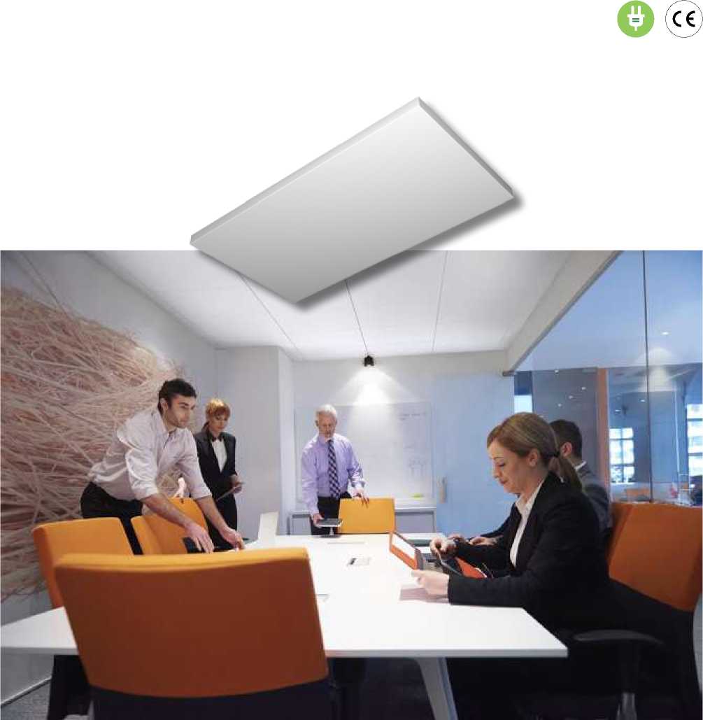
EnergoCassette can be used in false ceilings or directly onto the ceiling on supplied brackets. The heater is suitable for a wide range of installations in both dry and wet areas up to 4 m ceiling height. It frees valuable wall and floor surfaces.
The low surface temperature, no greater than 100°C, emits a gentle and comfortable heat, with energy savings up to 30% compared to a convective or hot air systems.
Energotech
ENERGY EFFICIENT HEATING SYSTEMS
How Does It Work?
The EnergoCassette, ENC, emits a gentle low temperature radiant heat to floors, walls and objects in a room. As a result, you can lower the air temperature in the room and still achieve an even and comfortable indoor climate, with energy savings up to 30% compared to a convective or hot air system.
The heater is suitable for low to medium ceiling heights. The stylish and elegant design suits offices, schools, hotels, showrooms, hospitals, hot yoga studios, residential homes etc.
The ceiling mount frees valuable floor and wall spaces, while the heater is protected from contact and damages. An excellent choice of heating system for public areas.
Use the EnergoCassette for a safe, trouble and maintenance free heating system, offering an even and comfortable indoor climate.
Design and Composition
EnergoCassette consists of a galvanized sheet steel plate which is powder coated in white - RAL9016. The backside of the heater, against the ceiling, is insulated. The heater is designed for a long life expectancy with a robust and durable heating element.
Technical Information
Output: 300W or 600W, 230V.
Appliance and protection class: Class I - IP55.
Mounting height: Up to approximately 4 m.
Connection: Fixed installation to a 4 mm² terminal block in the connection box. Connection between several heaters is possible.
Suspension: ENC can be mounted into a suspended ceiling system with visible grids of widths 15 mm or 24 mm. It is however equally suitable for surface mounting onto the ceiling, using the supplied H-bracket.
| |||||||||||||||||||||||||||||
|
Further information regarding mounting and installation can be obtained from our technical brochure. | |||||||||||||||||||||||||||||
Temperature control is simply carried out with use of our room thermostats or heating regulators.
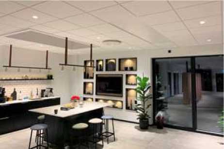 |
20.02.19-01EN |
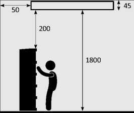
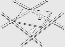
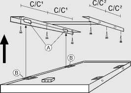
Energotech
Energotech AB | Firmagatan 5 | SE-213 76 Malmö, Sweden | +46 40 866 90 | info@energotech.se | www.energotech.com
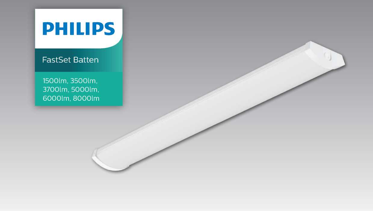
The decorative, easy to install LED replacement batten
The FastSet LED decorative batten is the perfect 1:1 replacement for conventional battens. With a wide profile and easy installation it simply fits into all different indoor applications. FastSet can be installed as a standlone luminaire or in a line configuration.
Features & Benefits
-
• One luminaire which is suitable for standalone or line configuration
-
• Good light quality and comfort thanks to its wide distibution
-
• Large terminal block ensures easy loop in loop out termination
-
• IP40 rating makes the FastSet resilient against dust
-
• 5 year Warranty
Production Specifications
| |||||||||||||||||||||||||||||||||||||||||||||||||||||||||||||||||||||||||||||||||||||||||||||||||||||||||||||||||||||||||||||||||||||||||||||||||||||||||||||||||||||||
|
*When a new fitting reaches 70% of full potential | |||||||||||||||||||||||||||||||||||||||||||||||||||||||||||||||||||||||||||||||||||||||||||||||||||||||||||||||||||||||||||||||||||||||||||||||||||||||||||||||||||||||
Flicker free Philips Office Elite Products utilise industry best LED drivers that deliver flicker1 free performance and no stroboscopic effect2 .
-
1 Additionally the Dali standard specifies 8 bit (256 discrete light levels) that can introduce the appearance of Flicker during transitions (dynamic dimming).
Dimming performance is improved with Elite Luminaires by the addition of further bits totalling 32,000 (15bit). These interpolated dimming levels protect against flicker artefacts during light level transitions.
-
2 In the absence of compulsory standards Philips Lighting opted to use the accepted test methods according to IEC TR 61547-1 [1] (Flicker) and IEC TR 61547-1 [5] (Stroboscopic Effect) with the following limits: PstLM ≤ 0.5 and SVM ≤ 1.
Dimensions
FastSet_Surface_Mounted-SM150C_L602
FastSet_Surface_Mounted-SM150C_L1160
FastSet_Surface_Mounted-SM150C_L1440
|
580 |
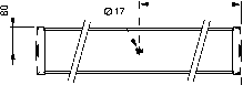 |
|
720 |
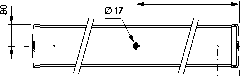 |
|
1040 ! 60 |
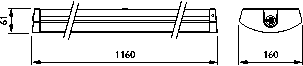 |
|
1320 1 60 |
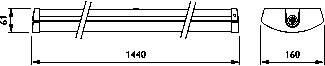 |
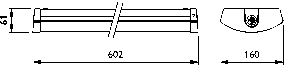
Dimensions shown above are nominal measurement. Slight variation in dimension may occur in production.
Order Placement Information

Version: October 2021
| |||||||||||||||||||||||||||
|
© 2019 Signify Holding. All rights reserved. Signify reserves the right to make changes in specifications and/or to discontinue any product at any time without notice or obligation and will not be liable for any consequences resulting from the use of this publication. Application images shown may not reflect actual products advertised. Signify New Zealand Limited Level 3, 123 Carlton Gore Road Newmarket, Auckland 1023 New Zealand T: 0800 454 448 / 0800 4 LIGHT Signify Australia Limited 65 Epping Road, North Ryde NSW 2113 Australia T: 1300 304 404 |
PHILIPS
Lighting
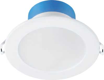
SmartBright LED Downlight DN029B
DN029B G2 LED8/CCT PSR-E D90 CAU
The SmartBright Downlight family is the perfect energy-efficient LED replacement for conventional downlights. It offers three solutions:;Solution 1;The energy-efficient LED replacement for conventional downlights;Essential SmartBright Downlight G3 DN029B-1 – this trailing- and leading-edge dimmable downlight is the ideal functional replacement for conventional downlights. This affordable and easy-to-install fitting delivers high energy savings without compromising on light quality.;Solution 2;Select the right colour temperature to suit your style;This hassle-free Essential SmartBright DN029B-2 downlight provides you with the flexibility to select the perfect colour temperature (Warm White/Cool White/Day Light) for the required use. Integrated with trailing/leading edge dimming capability, this affordable and easy-to-install fitting delivers high energy savings without compromising on light quality.;Solution 3;Enjoy the flexibility of a dimmable fitting without paying more;The Essential SmartBright DN029B-3 step dimming downlight is the perfect hassle-free replacement for conventional dimmable downlights. Adjust the light level directly from the switch and save money with installation as a dimmer unit is not required.
Product data
|
General Information |
Operating and Electrical | ||
|
Lamp colour code |
3000/4000/6500 |
Input Voltage |
220 to 240 V V |
|
Light source |
No |
Input frequency |
50 or 60 Hz |
|
replaceable |
Power factor (min.) |
0.8 | |
|
Luminaire light beam spread |
100° |
Controls and Dimming | |
|
Connection |
Plug-in connector 2-pole |
Dimmable |
Yes |
|
Protection class IEC |
Safety class II (II) | ||
|
Mechanical and Housing |
Initial chromaticity |
(3000K@, 0.4400, 0.40304000K@0.37600.36566500K@0.31300.3370) 6 | |
|
Housing material |
Metal–Plastic | ||
|
Reflector material |
Polycarbonate |
Initial input power |
7.5 W |
|
Optic material |
Polycarbonate |
Power consumption |
+/-10% |
|
Fixation material |
Stainless steel |
tolerance | |
|
Optical cover/lens |
Frosted | ||
|
finish |
Over Time Performance (IEC Compliant) | ||
|
Overall length |
114 mm |
Median useful life |
30000 h |
|
Overall width |
114 mm |
L70B50 | |
|
Overall height |
56 mm | ||
|
Overall diameter |
114 mm |
Application Conditions | |
|
Colour |
White |
Ambient temperature |
-20 to +40 °C |
|
Dimensions (height x |
56 x 114 x 114 mm (2.2 x 4.5 x 4.5 in) |
range | |
|
width x depth) | |||
|
Product Data | |||
|
Approval and Application |
Full product code |
871951425177900 | |
|
Ingress protection code |
IP40/IP54 front |
Order product name |
DN029B G2 LED8/CCT PSR-E D90 CAU |
|
Mech. impact |
IK03 [ 0.3 J] |
EAN/UPC – product |
8719514251779 |
|
protection code |
Order code |
929002531219 | |
|
SAP numerator – |
1 | ||
|
Initial Performance (IEC Compliant) |
quantity per pack | ||
|
Initial luminous flux (system flux) |
800 lm |
Numerator – packs per outer box |
12 |
|
Initial LED luminaire |
106.00 lm/W |
SAP material |
929002531219 |
|
efficacy |
SAP net weight (piece) |
0.230 kg | |
|
Lamp colour temperature |
3000 4000 6500 K | ||
|
Colour Rendering Index |
80 |
[iKOsj J | |
Dimensional drawing
|
5 |
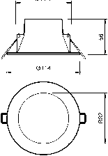 |
DN029B G2 LED8 3CCT 9W D90 DIM AU
Photometric data
Downlight DN029B G2 LED8 CCT PSR D90
Lifetime
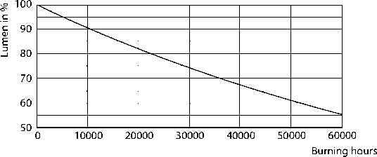
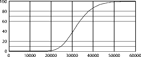
Time (hours)
B50L70 30K LMP
B50L70 30K LED

© 2021 Signify Holding All rights reserved. Signify does not give any representation or warranty as to the accuracy or completeness of the information included herein and shall not be liable for any action in reliance thereon. The information presented in this document is not intended as any commercial offer and does not form part of any quotation or contract, unless otherwise agreed by Signify. Philips and the Philips Shield Emblem are registered trademarks of Koninklijke Philips N.V.
|
composition acoustic wall coverings Product Specifications Total Product Weight: Typically 1600gsm Total Nominal Thickness: io-l2mm Finish: Available in fine velour or’'Classic" rib finish Roll Length/Width: Standard 25m x 1,22m Peel 'n' Stick Tiles: Tile Size: 600mm x 600mm Tile Pack: 6 tiles per pack (2.16m2 coverage) (Selected colours available only) 'Hook and Loop': Hook and loop compatible. A hook of 1.5mm or less is recommended Fire Ratings: AS1530 Part 3 Spread of Flame (Index 0-10) 0 Smoke Developed (Index 0-10) 5
AS/NZS 3837 Group 3 Ave Specific Extinction Area: 157.7m2/kg
BS476
Index i* = 5.2, Index r2 = 3.2, Index r3 = 0.8 Fire Propagation Index = 9.2
Fastness to Light: Composition is suitable for indoor use only and has been tested to the following standard ISO 105-B02-1994 (Grey Scale 1-5): Light Fastness Rating 3 Installation: Please refer to our Composition Installation Guide for installation instructions and hints. |
Acoustics: Composition’ has been tested to a Noise Reduction Coefficient (NRC) of 0.4 and wi II typical ly reduce reverberated noise by approximately 40% This graph illustrates the acoustic performance of Composition through the frequency range of 100 5000Hz. For copies of the full acoustic test report, please contact Autex. (Tested in accordance to ISO 354) 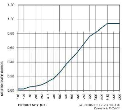
Composition has been engineered specifically to reduce and control reverberated (echo) noise in building interiors. Composition will also increase the sound transmission performance of walls. When adhered to one side of a wall, Composition provided a 3 STC point increase in the performance of the wall. For specific acoustic requirements, we recommend you consult an acoustic engineer. Service: For further information about Composition or any other Autex Wall Covering products, please contact your local distributor, an Autex Representative or visit our website at www.autex.co.nz |
|
Care & Maintenance: Please refer to our Autex Wall Coverings Care & Maintenance Guide for cleaning instructions. |
How to Specify: "Autex Composition acoustic wall covering with NRC0.4 fixed to the wall substrate in accordance with the manufacturers recommendations. Please contact Autex or your local distributor". |
Composition® is manufactured in New Zealand and is a registered trademark of Autex Industries Ltd. Autex reserves the right to a Iter specifications without prior
AUTEX

AUtKK FdLSflM Ltd 7C2 ?i6^csea:ncM Rrwfcsa^ZCBl taiisU-17^. Aik k hi>< kr^Tlrinrd
W ire *4*KC HVR«:n^ F. » -^Hf lF MIC
Fi i .i m> TCC 4.TR ^ WAHU4.<*JlUie
notification. Autex Industries Ltd is an ISO9001 certified company.
r: Bosca}
XV'I l^i pl p p ’’1-41.» irp
\T -I¥l.' rtrn.i
Pi . -11 KHKT&WI
E > -HU 3 VS 7 LCM
hspioa 1 TOFTS IT
«.^m^iiiparirruu
AutSXPty Ltd 1-^ tarf-Jk M,
All information offered on th is card is given in good faith but without warranty* Autex reserves the right to alter specifications without prior MtiftCMtolt Autex ts an ISO 9001 certified company* Slight variations in colourfrom the samples may be experienced due to the nature of the manufacturing process. Issue: COMP241108
Resene Paint Systems - Fire Ratings
Reserve
10 jMir.f this prr.fa'.jciCMi.^ -. ns*?
The listed Resene paint systems over the listed substrate have been fire tested using a cone calorimeter in accordance with ISO 5660 to determine Group Classification in accordance with New Zealand Building Code (NZBC) Verification Method C/VM2 Appendix A; National Construction Code (NCC) Volume One Specification C1.10 and A2.4 of the Building Code of Australia
|
Substrate |
Undercoat (1 coat unless otherwise stated) |
Topcoat (2 coats unless otherwise stated) |
Indicated Group No. |
Test Report |
|
10mm Paperfaced Plasterboard |
Resene Broadwall Waterborne Wallboard Sealer (SR 10 sqm/L) |
Resene SpaceCote Low Sheen (SR 15 sqm/L) |
1-S (NZBC) 1 (NCC) |
FH4967 |
|
10mm Paperfaced Plasterboard |
Resene Broadwall Waterborne Wallboard Sealer (SR 10 sqm/L) |
Resene SpaceCote Flat (SR 15 sqm/L) |
1-S (NZBC) 1 (NCC) |
FH4967 |
|
10mm Paperfaced Plasterboard |
Resene Broadwall Waterborne Wallboard Sealer (SR 10 sqm/L) |
Resene Zylone Sheen (SR 15 sqm/L) |
1-S (NZBC) 1 (NCC) |
FH4967 |
|
10mm Paperfaced Plasterboard |
Resene Broadwall Waterborne Wallboard Sealer (SR 10 sqm/L) |
Resene Ceiling Paint (SR 12 sqm/L) |
1-S (NZBC) 1 (NCC) |
FH4967 |
|
10mm Paperfaced Plasterboard |
Resene Sureseal (SR 15 sqm/L) |
Resene SpaceCote Flat (SR 14 sqm/L) |
1-S (NZBC) 1 (NCC) |
7-593235-CO |
|
10mm Paperfaced Plasterboard |
Resene Sureseal (SR 15 sqm/L) |
Resene Lustacryl (SR 14 sqm/L) |
1-S (NZBC) 1 (NCC) |
7-593262-CO |
|
13mm Paperfaced Plasterboard |
Resene Broadwall Waterborne Wallboard Sealer (SR 11 sqm/L) |
Resene ClinicalCote Satin (SR 14 sqm/L) |
1-S (NZBC) 1 (NCC) |
FH4925 |
|
13mm Paperfaced Plasterboard |
Resene Broadwall Waterborne Wallboard Sealer (SR 11 sqm/L) |
Resene ClinicalCote Low Sheen (SR 15 sqm/L) |
1-S (NZBC) 1 (NCC) |
FH4925 |
|
13mm Paperfaced Plasterboard |
Resene Broadwall 3 in 1 (SR 2.5 sqm/L) |
Resene ClinicalCote Satin (SR 14 sqm/L) |
1-S (NZBC) 1 (NCC) |
FH4925 |
|
13mm Paperfaced Plasterboard |
Resene Broadwall 3 in 1 (SR 2.5 sqm/L) |
Resene ClinicalCote Low Sheen (SR 15 sqm/L) |
1-S (NZBC) 1 (NCC) |
FH4925 |
|
13mm Paperfaced Plasterboard |
Resene Broadwall Surface Prep & Seal (SR 6 sqm/L) |
Resene ClinicalCote Satin (SR 14 sqm/L) |
1-S (NZBC) 1 (NCC) |
FH4925 |
|
13mm Paperfaced Plasterboard |
Resene Broadwall Surface Prep & Seal (SR 6 sqm/L) |
Resene ClinicalCote Low Sheen (SR 15 sqm/L) |
1-S (NZBC) 1 (NCC) |
FH4925 |
|
13mm Paperfaced Plasterboard |
Resene Broadwall 3 in 1 (2 coats) (SR 7 sqm/L) |
- |
1-S (NZBC) 1 (NZBC) |
FAR3981 |
|
13mm Paperfaced Plasterboard |
Resene Broadwall 3 in 1 (SR 7 sqm/L) |
Resene Zylone Sheen VOC Free (SR 16 sqm/L) |
1-S (NZBC) 1 (NZBC) |
FAR3981 |
|
13mm Paperfaced Plasterboard |
Resene Broadwall 3 in 1 (SR 7 sqm/L) |
Resene SpaceCote Low Sheen (SR 16 sqm/L) |
1-S (NZBC) 1 (NZBC) |
FAR3981 |
|
13mm Paperfaced Plasterboard |
Resene Waterborne Smooth Surface Sealer (SR 12 sqm/L) |
Resene SpaceCote Low Sheen (SR 16 sqm/L) |
1-S (NZBC) 1 (NZBC) |
FAR3981 |
|
13mm Paperfaced Plasterboard |
Resene Broadwall Waterborne Wallboard Sealer (SR 10 sqm/L) |
Resene Ceiling Paint (SR 12 sqm/L) |
1-S (NZBC) 1 (NZBC) |
FAR3981 |
|
6mm Fibre Cement Board |
Resene Quick Dry (SR 12 sqm/L) |
Resene Uracryl 802 (SR 16 sqm/L) |
1-S (NZBC) 1 (NCC) |
FH5139* |
|
6mm Fibre Cement Board |
Resene Quick Dry (SR 12 sqm/L) |
Resene Uracryl 803 (SR 16 sqm/L) |
1-S (NZBC) 1 (NCC) |
FH5139* |
|
6mm Fibre Cement Board |
Resene Sureseal (SR 12 sqm/L) |
Resene Uracryl 802 (SR 16 sqm/L) |
1-S (NZBC) 1 (NCC) |
FH5139* |
|
6mm Fibre Cement Board |
Resene Sureseal (SR 12 sqm/L) |
Resene Uracryl 803 (SR 16 sqm/L) |
1-S (NZBC) 1 (NCC) |
FH5139* |
|
8mm MDF |
Resene Quick Dry (SR 12 sqm/L) |
Resene Fireguard (SR 3.5 sqm/L) |
3 (NZBC) 3 (NCC) |
FH5137 |
|
8mm MDF |
Resene Quick Dry (SR 12 sqm/L) |
Resene Fireguard (SR 3.5 sqm/L), Resene SpaceCote Low Sheen (SR 14 sqm/L) |
3 (NZBC) 3 (NCC) |
FH5137 |
|
18mm MDF |
Resene Quick Dry (SR 12 sqm/L) |
Resene Fireguard (SR 3.5 sqm/L) |
3 (NZBC) 3 (NCC) |
FH5137 |
|
18mm MDF |
Resene Quick Dry (SR 12 sqm/L) |
Resene Fireguard (SR 3.5 sqm/L), Resene SpaceCote Low Sheen (SR 14 sqm/L) |
3 (NZBC) 3 (NCC) |
FH5137 |
|
9mm thick 'A' grade plywood |
Resene Aquaclear Semi-Gloss |
Resene Aquaclear SemiGloss (3 coats SR 12 sqm/L) |
3 (NZBC) |
FAR3981 |
|
≥ 26mm Metrapanel |
Pre-primed |
Resene Fireguard (SR 1 sqm/L), Resene SpaceCote Low Sheen (SR 16 sqm/L) |
1-S (NZBC) 1 (NCC) |
FH5334 |
Notes:
Test reports give the Group rating determined by application of a paint system to a given substrate thickness. The same Group rating applies to the paint system applied to greater thicknesses of the substrate given in the test report.
The Group rating of a given substrate coated with a standard 3 coat acrylic paint system will be the same as the uncoated substrate.
FH5139*
It is considered that the resulting Group Classifications achieved by paint systems on fibre cement substrates would not be adversely affected if applied to a concrete substrate. Paint system applied at coverage rates not less than the minimum specified for the fibre cement substrate.
31 Jan 2014
10
SLIDING & FOLDING
SLIDING AND FOLDING
FOR SLIDING FRAMELESS GLASS DOORS - INFRONT
EKU CLIPO 16 GPK/GPPK
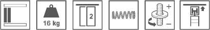
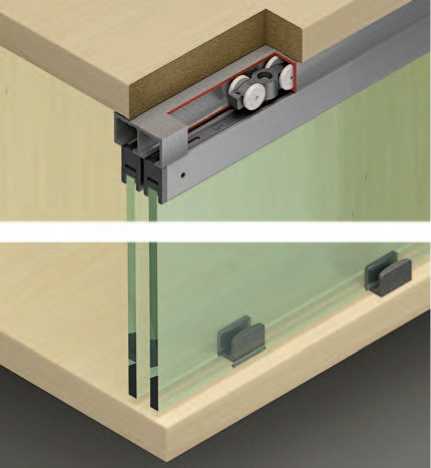
-
> Version: Model GPK with top glass retaining
profile and visible bottom guide with zero clearance.
Model GPPK with top and bottom glass retaining profile and concealed bottom guide with zero clearance, with soft closing mechanism (optional)
-
> Door height (mm): ≤1400
-
> Door width (mm): ≤1000
-
> Glass thickness (mm): 6
-
> Door stopper: Top door stopper
-
> Material: Plastic
-
> Running gear: Top running, 2 rollers
-
> Running gear guided by:Friction bearing mounted roller: Plastic,
-
> Adjustment facility (mm): +2/-1 on running gear
-
> Installation: Running gear without tools
(quick fixing system), guide for screw fixing without glass preparation
|
Running gear installation |
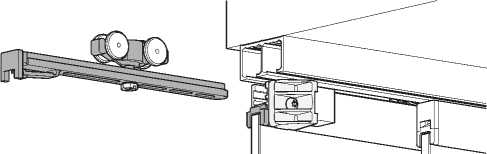 |

 |
|
Minimum door width for one soft close mechanisms - 400 mm |
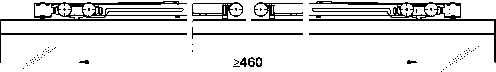 |
|
Minimum door width for two soft close mechanisms - 600 mm |
HAFELE
|
Installation dimensions |
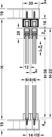 |
Clipo 16 GPK; with glass fixing profile at the top
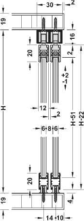
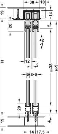
Clipo 16 GPPK; with glass fixing profile top and bottom
Door overlap
|
A A+16 2 |
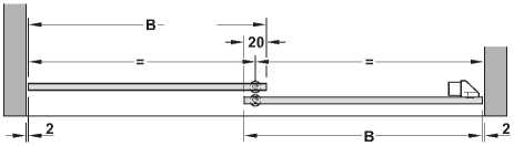 |
A = Internal cabinet width H = Internal cabinet height B = Door width
Dimensions in mm Dimensional data not binding. We reserve the right to alter specifications without notice.
Revision: 1.0
Caroma
Luna Cleanflush™
Vitreous China 4.5/3 litre Dual Flush Wall Faced
Close-Coupled Rimless Toilet Suite
Date: February 2017
Supersedes all previous issues
3.19.2

Caroma
Luna Cleanflush™
Vitreous China 4.5/3 litre Dual Flush Wall Faced Close-Coupled Rimless Toilet Suite
 |
|
cleanflush |
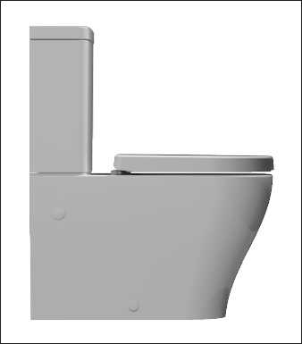
Combining a contoured design with rimless pan technology, the Luna Cleanflush™ is a superior flushing system suitable for domestic and commercial applications. Incorporating several patented technologies: Caroma Flow Splitter™, Caroma Flow Balancer™ and Caroma Uni-Orbital® Connector, the Cleanflush pan is innovative and the next evolution in toilets. The Flow Splitter evenly flows water around the top of the bowl to meet at the Flow Balancer which directs the water powerfully into the sump, reducing the need for brush cleaning. The rimless pan is easy to clean and unlike traditional pan profiles, provides full visibility of any grime build up. Caroma Cleanflush™ provides a cleaner clean for peace of mind.
Pan: Luna Cleanflush™ wall faced close coupled 4.5 litre full flush rimless pan.
Traps: Universal trap for S or P-trap installations.
Cisterns: Universal close coupled cistern – has a free fitting lid and is suitable for domestic
and light commercial applications. Available with internal overflow. Available in either back entry or bottom inlet options.
Cistern inlet stop valve and inlet connection is concealed within the cistern and is included (back entry version only). Vandal Resistant Conversion Kit – A simple to install conversion is available for the standard mechanism to lock lid onto the cistern, recommended for use in heavy use commercial areas. Code No.750109. Important: Working pressure minimum 30kPa to maximum 1000kPa flow pressure. Rain water tank compliant. Accurate wall setout for B.S.P. 1/2" Nipple water inlet connection is essential.
Fixing: The cistern is fixed directly to the pan with a robust concealed base fixing system
without the need for wall fixing.
Seats: The Xena soft close quick release thermoset toilet seat is provided as standard
with the Urbane Cleanflush™ suite. See chapter 5.01 SEATS of the Caroma Technical Manual for further details.
Colours: White only.
Installation: The installation of the toilet suite shall be in accordance with the normal minimum
drainline grade requirements in AS/NZS 3500.2.
Dimensions: All dimensions are in millimetres and are subject to normal manufacturing variations.
Caroma pursues a policy of continuing improvement in design and performance of its products. The right is therefore reserved to vary specifications without notice.
|
373 |
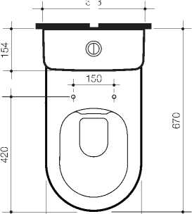
150 |
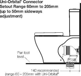 |
|
connector supplied - up to 50mm sideways adjustment) |
Luna Cleanflush™ Wall Faced
Close Coupled Toilet Suite with
Xena Soft Close Seat Code No.
4.5/3 litre Bottom Inlet
Internal Overflow 844810
4.5/3 litre Back Entry
Internal Overflow 844820
50
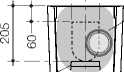 |
|
Waste outlet |
Uni-Orbital® connector can be positioned anywhere in shaded area up to 50mm.
|
350 |
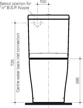 |
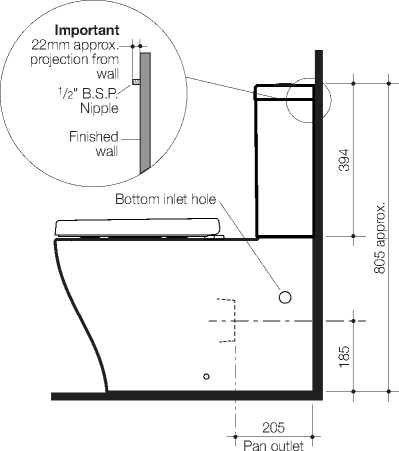 |
Note: All height dimensions to underside of pan, make allowance for bedding when installing. Bedding: The pan should be fixed to the floor with a sand cement mixture of 3:1 to a depth of 60mm. Do not use lime or fast drying cement in the bedding mixture. When bedded the back of the foot of the pan should be approximately 10mm above the finished floor. Bracket fixing: The pan should be bedded with an acetic cured silicone sealant and fixed with the D82 Fixing Brackets supplied. |

Pan seal
|
D82 Concealed Fixing Bracket |
 |

Caroma Industries Limited ABN 35 000 189 499
Sales Offices in all States.
Caroma
design for life
Date September 2014
17.14
Cosmo
Vitreous China Wall Basin
Basin Size: 500mm x 440mm (nominal)
&

Contemporary style doesn’t have to mean edges and angles, nor does it have to cost the earth. The Caroma Cosmo wall basin is surprisingly economical whilst offering elegant curves and a very modern aesthetic. Due to its compact size, a wall basin has always been a practical choice. With the addition of a shroud, it becomes a beautiful one as well. The basin is suitable for domestic, commercial and accessible applications X complying to AS 1428.1-2009 Amd. 1 using standard Caroma plastic traps.*
Tap Holes: Basin available in: one taphole – centre option Code No.861515; three taphole
option Code No.861535.
Tapware - other All electronic and basin care mixers referred to in section 19 comply to than sole AS1428.1-2009 Amd. 1 installations other than sole occupancy unit when occupancy unit: matched with this basin.
Tapware - sole Recommended tapware for sole occupancy unit for compliance to AS1428.1-2009 occupancy unit: Amd. 1; Electronic Tapware: Designo, Designo Solar, Mix Neu and Celis.
See section 19 for further details.
Tapware is shown for photographic purposes only
Waste Outlet: Chrome flush fitting waste and white plug supplied, suitable for a 40mm trap connection. Alternative waste options are available — Chrome grate waste and white plug Code No.687328C, Vandal Resistant Flush Fitting Plug and Chrome Waste Code No.687141, Covered Plug and Waste Code No.687142 and Vandal Resistant Covered Chrome Plug and Waste Code No.687143.
Shroud: Shroud, Code No.639950, completely conceals P-trap waste pipe fittings. Use
D.210 fixing clip suitable with D.200 bracket option and 40mm Caroma plastic P-trap Code No.102112. Note: It is essential for the installation of the shroud to the basin that clearance is provided for the shroud in the plumbing setout from water inlet pipes and connections.
Bowl Capacity: 4 litres to overflow.
Overflow: Overflow available only. Designed for maximum tap flow rate of 15 litres/minute.
Fixing: D.200 Basin Fixing Kit – Supplied. Bolts directly to the finished wall.
Colours: White.
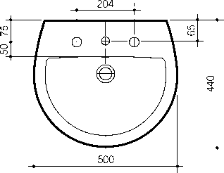 |
|
D.200 basin fixing kit hole centre positions |
|
D.200 Basin Fixing Kit |
 |
|
D.210 Concealed Fixing Clip Assembly included with shroud |
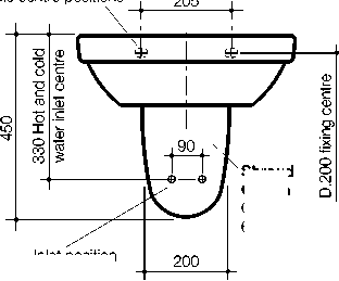 |
|
Inlet position to allow for shroud |
Shroud
Option
Code No. 639950
Finished Floor
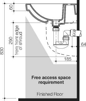
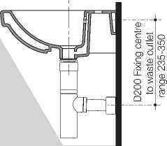 |
|
Free access space requirement |
Finished Floor
Suitable for installation to comply to Australian Standard AS 1428.1-2009 Amendment No.1 Design for access and mobility
METHVEN
GLIDE BASIN MIXER
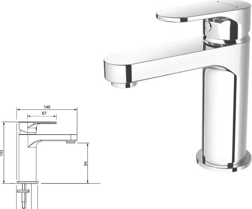 |
|
050 |

|
GLBCP
GLBBK
Chrome
Matte Black
https://www.methven.com/nz/glide-basin-mixer
FREEPHONE 0800 804 222 | FAX ORDERS 0800 805 222 | EMAIL CUSTOMERCARE@NZ.METHVEN.COM methven.com

Tork® Matic® Hand Towel Roll Dispenser

|
Article |
551000 |
|
Material |
Plastic |
|
System |
H1 - Hand towel roll system |
|
Height |
372 mm |
|
Width |
337 mm |
|
Depth |
203 mm |
|
Colour |
White |
The Tork Matic® Hand Towel Roll Dispenser in Elevation Design delivers easy maintenance to keep busy washrooms functioning and reduces consumption with one-at-a-time sheet dispensing. Tork Elevation dispensers have a functional, modern design, that makes a lasting impression on your guests.
-
* Reduce consumption by up to 50% with
-
• Tork® Matic H1 System and controlled single sheet dispensing (vs Roll Towel)
-
• Reduce servicing with Tork® Matic H1 refills that last up to six times longer than a
-
• standard roll towel
-
• Reduce impact - use less, waste less and choose FSC certified or 100% recycled refills
Shipping data
|
Consumer unit |
Transport unit | |
|
EAN |
7322540348941 | |
|
Pieces |
1 |
1 |
|
Consumer units |
1 | |
|
Height |
372 mm |
417 mm |
|
Width |
203 mm |
209 mm |
|
Length |
337 mm |
340 mm |
|
Volume |
0 dm3 |
29.6 dm3 |
|
Net weight |
3180 g |
3.2 kg |
|
Gross weight |
3680 g |
3.7 kg |
|
Packing material |
Carton |
Carton |

Choose a refill that suits you
|
Tork® Matic® Soft Hand Towel Roll Advanced |
290067 |
|
Tork® Matic® Extra Soft Hand Towel Roll Premium |
290016 |
|
Tork® Matic Extra Long Hand Towel Roll Universal |
290059 |
Alternative products

552200 559030 558038
Contact
New Zealand
Sales & Support Centre
0800 523 565
Free phone 0800 523 565
Private Bag 93100
Henderson, Auckland 0650
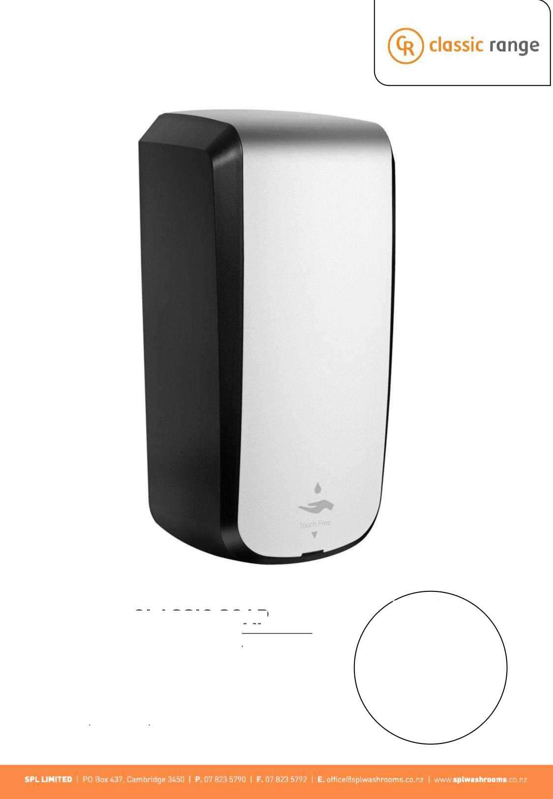
SUPREME CLASSIC SOAP
Automatic Foam Soap Dispenser
-
■ Hygienic hands free operation
-
■ Economic and efficient
-
■ Simple refill replacement
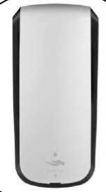
SUPREME CLASSIC SOAP DISPENSER
The Supreme Classic Soap Dispenser is a hands free automatic wall mount foam soap dispenser, available in two stylish finishes. The foam soap is dermatologically tested and provides smooth velvety foam suitable for sensitive and dry skin. Foam Soap refills are quick and easy to replace.
COLOUR OPTIONS

Silver & Black


SPECIFICATIONS
Operation Capacity Portion Control Power Dimensions Warranty Refill
Automatic Non-Touch
1100 ml - Up to 2750 portions 0.3-0.4 ml
Requires 4 x C size batteries 282H x 124W x 115D mm 12 months excludes battery
Foam Soap - dermatologically tested
SPL LIMITED I PO Box 437. Cambridge 3450 | P. 07 823 5790 I F. 07 823 5792 I E. officefflsplwashrooms.co.nz I www aplwathroomi co nz

Tork® Mini Jumbo Toilet Roll Dispenser
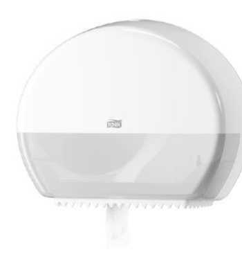
|
Article |
555000 |
|
Material |
Plastic |
|
System |
T2 - Mini jumbo toilet system |
|
Height |
275 mm |
|
Width |
345 mm |
|
Depth |
132 mm |
|
Colour |
White |
Tork® Mini Jumbo Toilet Roll Dispensers hold up to 400m of toilet paper, all in a compact dispenser perfect for areas with limited space.
Compact size perfect for areas with limited space
Reduce waste with the stub roll feature
Simple and intuitive to service with semi transparent window
Shipping data
|
Consumer unit |
Transport unit | |
|
EAN |
7322540354843 | |
|
Pieces |
1 |
1 |
|
Consumer units |
1 | |
|
Height |
275 mm |
284 mm |
|
Width |
132 mm |
139 mm |
|
Length |
345 mm |
352 mm |
|
Volume |
0 dm3 |
13.9 dm3 |
|
Net weight |
927 g |
0.9 kg |
|
Gross weight |
1000 g |
1.2 kg |
|
Packing material |
Carton |
Carton |

Choose a refill that suits you
Tork® Extra Soft Mini Jumbo Toilet Roll Premium
Tork® Mini Jumbo Toilet Roll
Universal
Tork® Recycled Mini Jumbo Toilet Roll Advanced
Alternative products

555500 557500 554030
Contact
New Zealand
Sales & Support Centre
0800 523 565
Free phone 0800 523 565
Private Bag 93100
Henderson, Auckland 0650

IKON PRODUCT INFORMATION 12-14 Charlies Way, Frankton, Hamilton, New Zealand, 3204 Phone 0800 83 83 84 Fax 0800 83 83 85 iKoni |
Centurio 1.5 IK723143I (Intergrated/Laser edge)
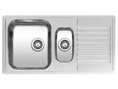
$629.00
Description
Ikon are excited to be able to now offer stainless steel sinks with iKolor-ed wastes and overflows. All you need to do is:
-
1. Add your chosen sink to the cart
-
2. It is important you choose the correct kit for the sink you are ordering.
For this specific sink, we recommend a double (waste only). Click on the link then continue with the following instructions:
-
3. Choose your iKolor preference
-
4. Add it to your order.
-
5. Then continue with your online order as usual (please allow 7-12 working days dispatch for any iKolor-ed products)
For any advice before placing your final order, please don’t hesitate to contact us.
-
• Standard Reginox overflow
-
• Polished finish
-
• 304 High grade Stainless Steel
-
• Can be flush, under or top mounted (refer to your fabricator)
-
• Comes complete with clips, waste and overflow
-
• Undermount collar available
-
* Suggested cabinet size: 60cm
-
* Reversible
This product has a lifetime warranty from the date of original purchase. For more information please refer to our FAQ’s section on sink warranties
CLICK HERE FOR THE LATEST BROCHURE
|
Additional information | ||||
|
|
Images |
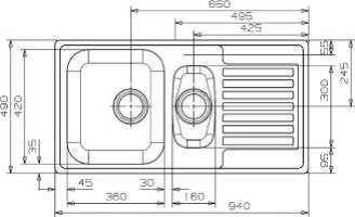 |
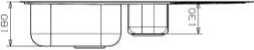
[wcsp_cross_sell orderby="rand" order="ASC" product_num="5" display_columns="3" title="Hello title.." product_id="Product ID"]
METHVEN
GLIDE SINK MIXER
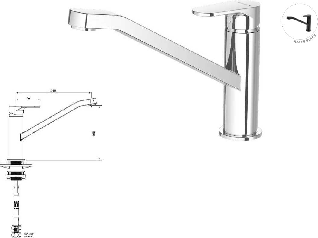
CONSTRUCTION: Brass body
CARTRIDGE TYPE: 25 mm ceramic
SUPPLY: Suitable for mains pressure only INLET CONNECTIONS: 1/2 “ BSP Female WORKING PRESSURE: 150 - 1000kPa
-
• Solid brass construction for longevity
-
• Twin screw mounting for secure basin installation
-
• Stainless steel flexible inlet hoses
-
• Solid, easy to grip handle
-
• Swivel spout fitted with aerator
-
• 5 star WELS rating on 5.5l/m
DIMENSIONS FOR FITTING: 35 - 38 mm diameter hole
|
OPERATING TEMPERATURE: 5 °C - 80 °C | ||||||
| ||||||
FREEPHONE 0800 804 222 | FAX ORDERS 0800 805 222 | EMAIL CUSTOMERCARE@NZ.METHVEN.COM methven.com
NAENAE COLLEGE ADMINISTRATION
910 HIGH STREET
AVALON
LOWER HUTT 5011
MECHANICAL SERVICES - VENTILATION
Drawing Index
CONSENT ISSUE
Prepared By:

|
SHEET |
SHEET TITLE |
|
M-01 |
Cover |
|
M-02 |
Legend |
|
M-03 |
Equipment Schedule and Ventilation Summary |
|
M-04 |
System Layout |
General Notes
-
- All work to comply with current edition of New Zealand Building Code (NZBC), relevant standards and statutory requirements for mechanical ventilation. Work to be carried out as per industry best practice and to good workmanship.
-
- This mechanical ventilation specification is in accordance with the requirements of NZBC G4/AS1. To ensure compliance, outdoor airflow rates are calculated as per NZS 4303 Ventilation Rate Procedure, and exhaust airflow rates as per AS1668.2. If at a later time, space use changes and/or new contaminants are introduced, then this design will need to be re-evaluated by Simx.
-
- Equipment locations and system layouts are a guide only, based on the information provided at the time, and without the benefit of an onsite inspection. Contractor to coordinate with other trades to ensure that the systems will fit in the designated spaces, confirm all required products and prepare shop drawings.
-
- All dimensions are in millimetres (mm), duct dimensions are the air stream sizes, and other dimensions are the nominal sizes unless otherwise specified (e.g. face size, neck size). Refer to product dimensional data and installation manual when determining space requirements.
-
- Requested fan static pressure is an estimate only, based on the pressure drop allowance across the index run of the particular system. Where the actual system layout is expected to vary significantly from the proposed layout thereby affecting airflow delivery, the contractor is to verify fan suitability with Simx.
-
- Systems to be designed, installed, and commissioned as per AS/NZS 3666.1, with specific requirements as per AS 1668.2 and other applicable standards, using materials and methodology to ensure compliance with NZBC B2 Durability. Systems to be maintained to ensure compliance with NZBC H1 Energy Efficiency (clause H1.3.6).
-
- Ductwork to be constructed and installed as per SMACNA HVAC Duct Construction Standards, AS 4254 (parts 1 and 2 as applicable), and other applicable standards.
-
- Weatherproofing of roof and external wall penetrations to comply with NZBC E2/AS1. Penetration details to be prepared by architect or registered building practitioner.
-
- Firestopping to be specified and installed where components penetrate fire walls, floors and ceilings. Smoke dampers to be specified and installed as required.
-
- Acoustic dampening to be specified and installed where components penetrate acoustic rated building elements, and/or system noise exceeds space acoustic requirements. Vibration dampening to be installed as required.
-
- Seismic restraints to be specified and installed for mechanical plant and systems in accordance with the requirements of NZS 4219.
-
- Fans to be accessible for service and maintenance as per New Zealand Electrical Regulations. All other plant, equipment and components to be accessible for service and maintenance as per AS/NZS 3666.2.
-
- All electrical work to comply with the requirements of AS/NZS 3000 and other applicable electrical standards. Wiring and additional required controls to be provided by the contractor.
|
K K 3 |
Supply Diffuser Supply Diffuser (3-way/2-way opp/2-way cnr) |
|
Swirl Diffuser | |
|
Il 1 1 ~ll |
Slot Diffuser w/ Plenum |
|
Exhaust/Return Grille | |
|
Louvre Grille | |
|
c |
Wall Cowl |
|
Roof Cowl | |
|
Wye Branch | |
|
Branch Take-off | |
|
Double Branch Take-off | |
|
Bevelled Junction | |
|
[^ |
Tee Junction |
|
Bend | |
|
Transition | |
|
Offset Transition | |
|
Manual Damper | |
|
Back-draught Shutter | |
|
ea (^ |
Circular duct cross-section (towards/away) |
|
Rectangular duct cross-section (towards/away) |
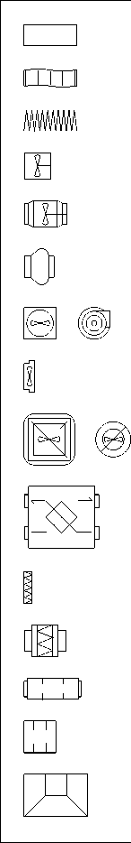
Rigid Duct
Sem-rigid Duct
Flexible Duct
Inline Axial Fan
Inline Mixed Flow Fan
Inline Centrifugal Fan
Ceiling Fan
Wall Fan
Roof-mounted Fan
Heat Recovery Unit
Air Filter
Air Filter + Box
Silencer (Circular)
Silencer (Rectangular)
Rangehood
|
Flexible duct recommended airflow | |
|
Size (mm) |
Airflow (L/s) |
|
ø150 |
25 – 54 |
|
ø200 |
55 – 96 |
|
ø250 |
97 – 152 |
|
ø300 |
153 - 220 |
|
ø350 |
221 - 300 |
|
ø400 |
301 - 390 |
 |
Simx Limited 1 Haliday Place, East Tamaki, Auckland 2013 PO Box 14347, Panmure, Auckland 1741 P: +64 9 259 1660 | F: +64 9 259 1661 |
|
CLIENT: |

PROJECT:
Naenae College Administration
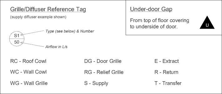
|
Duct Reference Tag (sizes shown are examples only) | ||
|
Ø2 EA Function ø200 Circular duct air stream diame 300x150 Rectangular duct air stream si Function: OA - Outdoor Air EA - Exhaust Air SA - Supply Air Lining: N - Nude |
0 / |
■J |
|
ter in mm ze in mm RA - Return Air TA - Transfer Air I - Insulated | ||
|
Equipment Reference Tag | ||
|
(supply fan example shown) | ||
|
Supply Air Fan |
Fan 1 | |
|
SAF – 01 | ||
|
100 L/s |
Total Airflow Rate |
|
Other Reference Tag | |
|
SAF - Supply Air Fan |
ATT – Attenuator/Silencer |
|
EAF - Exhaust Air Fan |
AF - Air Filter |
|
TAF - Transfer Air Fan |
MD - Manual Damper |
|
HRU - Heat Recovery Unit |
BD - Back-draught Shutter |
ADDRESS / LEGAL DESCRIPTION:
910 High Street, Avalon, Lower Hutt 5011
SHEET TITLE:
Legend
|
DESIGNED: AM |
REVIEWED: - |
DATE: 27/10/2021 |
|
SCALE: NTS |
REV.: B |
SHEET: M-02 |
|
FAN SCHEDULE | |||||||||||
|
Ref. |
Serving |
Type |
Manufacturer |
Model |
V/Ph/Hz |
Motor (kW) |
FLC (A) |
Requested Duty |
Order Code |
Operation |
*Control |
|
EAF-01 |
WC1, WC2, and WC3 |
Inline – Mixed Flow |
Simx |
IMF-150SIL-EC |
230/1/50 |
0.073 |
0.48 |
85 L/s @ 120 Pa |
FAN6858 |
Continuous |
Speed controller for commissioning (supplied), master HVAC control system with isolation switch for service and maintenance (by others). |
|
GRILLE, DIFFUSER, & COWL SCHEDULE | ||||||||
|
Ref. |
Type |
Manufacturer |
Model |
Nom. Neck Size (mm) |
Neck Adaptor/ Plenum Box |
Airflow (L/s) |
Order Code |
Comments |
|
E1 |
Ceiling Grille |
Simx |
Eggcrate Round |
Ø150 |
- |
25-35 |
DCT2608 |
w/ inbuilt damper |
|
RC1 |
Roof Cowl |
Simx |
General Purpose |
Ø150 |
- |
85 |
DCT0172 |
c/w 0.5m HPDE tube + EPDM flashing |
|
DG1 |
Door Grille |
Simx |
DRAG |
300x300 |
- |
- |
DCT3486 |
c/w 2-pieces for both sides of door |
|
MD |
Manual Damper |
- |
- |
Ø150 |
- |
- |
- |
Part of duct system (by others) |
|
VENTILATION SUMMARY | |||||||||||
|
Room |
Floor Area m² |
Number of Fixtures |
Number of Occupants |
Ventilation Type |
Ventilation Rate (L/s) |
Minimum Airflow (L/s) |
Design Airflow (L/s) |
Comments | |||
|
Per Room |
Per Sqm |
Per Fixture |
Per Person | ||||||||
|
WC1 |
1.98 |
1 |
- |
Extract |
- |
10 |
25 |
- |
25 |
25 |
Make-up air via door grille DG1 and 25mm under-door gap. |
|
WC2 |
1.98 |
1 |
- |
Extract |
- |
10 |
25 |
- |
25 |
25 |
Make-up air via door grille DG1 and 25mm under-door gap. |
|
WC3 |
3.47 |
1 |
- |
Extract |
- |
10 |
25 |
- |
35 |
35 |
Make-up air via door grille DG1 and 25mm under-door gap. |
|
Simx Limited & ^* 11 1 Haliday Place, East Tamaki, Auckland 2013 < T v*imv PO Box 14347, Panmure, Auckland 1741 P: +64 9 259 1660 | F: +64 9 259 1661 |
CLIENT: |
PROJECT: Naenae College Administration |
ADDRESS / LEGAL DESCRIPTION: 910 High Street, Avalon, Lower Hutt 5011 |
SHEET TITLE: Equipment Schedule & Ventilation Summary |
DESIGNED: AM |
REVIEWED: - |
DATE: 27/10/2021 | ||||||
|
RESOLVE1? | |||||||||||||
|
B |
27/10/21 |
Remove passive transfer system, add door grilles. |
AM |
■ acHiitcn |
SCALE: NTS |
REV.: B |
SHEET: M-03 | ||||||
|
A |
26/10/21 |
Original Issue |
AM | ||||||||||
|
REV. |
DATE |
DESCRIPTION |
BY | ||||||||||
Duct Reference
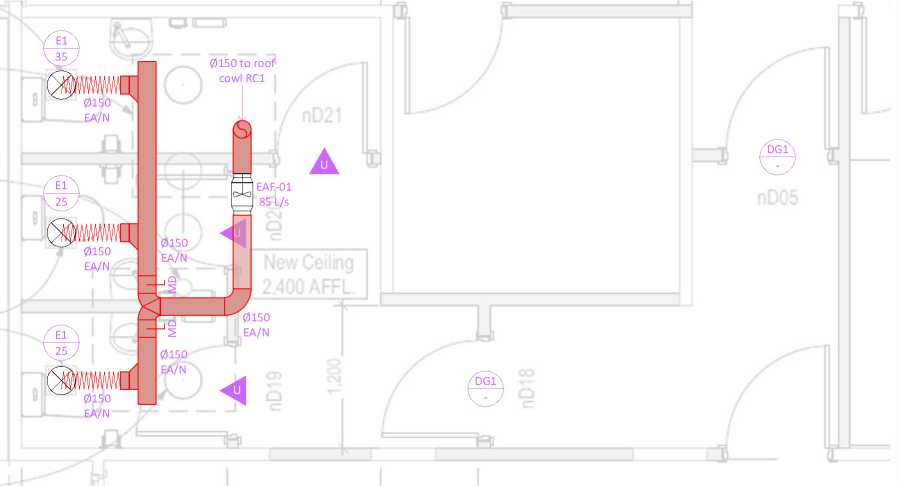
GROUND FLOOR NTS
|
Legend | ||||||||||||||||||
| ||||||||||||||||||
|
*Refer to Drawing Notes | ||||||||||||||||||
Drawing Notes:
-
- Weatherproofing, fire stopping, seismic restraint, acoustic dampening, and vibration dampening to be provided by others as required.
-
- Duct system to be provided by contractor. Sizes to be confirmed before construction.
-
- All supply and return duct to be insulated with min. 25mm lining (internal or external).
-
- All extract duct to be nude; use externally insulated duct with min. 25mm lining in colder environments.
-
- Flexible duct not to exceed 6m for main runs, and 3m for take-off runs.
-
- Minimum separation distances to be maintained from discharges to intakes, natural ventilation openings and boundary.

-
- Use speed controller to adjust fan speed to meet design airflow rate. Refer to equipment schedule.
Original drawing in colour
-
- Use inline balancing damper and grille adjustable damper to balance airflow in each area.
-
- Access panels to be provided for service and maintenance.
Consent issue. Not for construction.
-
- All dimensions are in millimetres (mm), duct dimensions are the air stream sizes, and other dimensions are the nominal sizes.
-
- Do not scale from this drawing.
€^ Simx
|
Simx Limited 1 Haliday Place, East Tamaki, Auckland 2013 PO Box 14347, Panmure, Auckland 1741 P: +64 9 259 1660 | F: +64 9 259 1661 |
CLIENT: | |||||
|
RESOLVE'7/ | ||||||
|
B |
27/10/21 |
Remove passive transfer system, add door grilles. |
AM |
• ■CHITtCO | ||
|
A |
26/10/21 |
Original Issue |
AM | |||
|
REV. |
DATE |
DESCRIPTION |
BY | |||
|
PROJECT: |
ADDRESS / LEGAL DESCRIPTION: |
SHEET TITLE: |
DESIGNED: |
REVIEWED: |
DATE: |
|
Naenae College Administration |
910 High Street, Avalon, Lower Hutt 5011 |
System Layout |
AM |
- |
27/10/2021 |
|
SCALE: |
REV.: |
SHEET: | |||
|
NTS |
B |
M-04 |
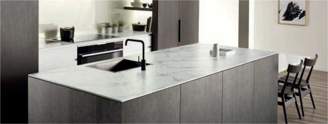
|
Melteca® is a tough melamine surface laminated to Superfine® particleboard or Lakepine medium density fibreboard (MDF) to provide a double faced, pre-finished decorative panel. Melteca is available in five different finishes and a range of colours, patterns and woodgrains. These are presented in the Melteca colour brochure and on the Melteca website. COMPOSITION Sheets of melamine impregnated overlay are bonded to both sides of either Superfine particleboard or Lakepine medium density fibreboard substrate under heat and pressure. The resin on the top surface of the overlay cures, forming a tough, stain resistant finish. Sheets are identified by Melteca branding, including colour and other manufacturing details along the panel edges. Packs are clearly identified with the distinctive brand label. USES
|
For uses other than those specified in this section, and for use in the construction industry, please contact Laminex New Zealand on 0800 303 606. SPECIFYING When specifying Melteca, include the following information:
|
DESIGN CONSIDERATIONS Edge finishing The edges of Melteca panels should be finished with a PVC or ABS edgetape solution. For the range of thicknesses, colours and finishes available, refer to the Melteca Availability Guide at melteca.co.nz Note: Any exposed substrate must be sealed before service. Load bearing applications Melteca is suitable for load bearing applications such as shelving, tables, desks, store displays, shop fittings, and kitchen cabinets. When designing these load bearing items the tables below can be used to establish the correct support spacings to achieve an acceptable deflection for a given loading. | ||||||||||||||
Shelf loading span tables*
|
Single span shelf | ||||||||
| ||||||||
|
Multiple span shelf | |||||||||||||||||||||||||||||||||||||||
| |||||||||||||||||||||||||||||||||||||||
| ||||||||||||||||||||||||||||||||
|
*Spans based on creep factor of 2 with final deflection of 0.006 x span **Loadings uniformly distributed. |
|
Performance data | ||||||||||||||||||
| ||||||||||||||||||
|
Melteca complies with the requirements of AS/NZS 1859.3 2005 |
|
LIMITATIONS
|
|
|
|
HANDLING AND STORAGE
Melteca must be protected from the weather, dampness and direct wetting and should be stored inside. Fungal and insect resistance Melteca is resistant to fungal decay and insect attack providing the moisture content of the panels does not exceed 18%. |
FIRE PERFORMANCE The Group Number Classifications below were generated from tests carried out and data recorded in accordance with the test procedure described in ISO 5660 2002 – Reaction-to-Fire – Part 1: Heat Release & Part 2: Smoke Production Rate, for the purposes of determination of the Group Classification in accordance with the New Zealand Building Code Verification Method C/VM2 Appendix A Melteca bonded to Lakepine Medium Density Fibreboard (MDF) substrate Group Number Classification 3 Please note: Indicative testing has indicated a change in substrate to Lakepine MRZero or Superfine particleboard (Standard or MR) will not alter the Group Number Classification. Effects of heat Precautions must be taken to ensure that Melteca is kept clear of nearby heat sources, such as free standing fire places |
and space heaters, wall ovens, hot plates etc. The structural life of the substrate may be impaired if temperatures exceed 50°C for prolonged periods. Melteca can withstand short term exposure to temperatures of 65°C above ambient without fear of ignition. Manufacturers of heat appliances, referenced above must be consulted to ensure that correct clearances and ventilation are provided for. DURABILITY When stored, handled, used and maintained in accordance with this document, Melteca will meet the durability requirements of the NZBC B2.3.1(c) and carries a 7 year limited warranty. Laminex New Zealand will not be liable to any person for any product failure if the conditions as to storage, handling, use and maintenance of Melteca as outlined within this document are not complied with. |
|
DIMENSIONS | ||||||||||||||||||||||||||||||||||||||||||
| ||||||||||||||||||||||||||||||||||||||||||
|
(i) Includes Lakepine MDF, Lakepine MRZero (ii) Includes Superfine and Superfine MR | ||||||||||||
| ||||||||||||
|
WORKING RECOMMENDATIONS Machining To obtain the best results when machining Melteca, avoid excessive speed rates.
As these are examples taken from various tooling manufacturers, please consult with your tooling supplier to ensure safe operating speeds are used. |
A saw fitted with a scribing saw or hollow ground saw blade will produce the best result directly from the sawing equipment. This will eliminate further work prior to edge finishing. However, sophisticated machinery is not always necessary to achieve quality edge finishes, A sharp bench saw buzzer or router combination or for the home handyperson, a fine tooth panel saw, hand-planer combination can be used to give excellent results. In both applications, panels should be cut slightly oversize and then edges planed to final dimensions. To avoid excessive breakout when hand-sawing, keep saw on a low angle to the sheet, provide adequate support to the sheets and do not force saw-blades through the cut. Gluing The surface of Melteca is made to withstand resistance to adhesion, however, this can cause problems with some glues. For gluing of Melteca to Melteca surfaces, |
abrading of the surface is required and the use of a Melamine adhesive such as Woodlock 3100 is recommended. For using as a wall lining, framing must be dry and a suitable wall board adhesive such as Maxbond should be used after first sanding the surface to provide a key for adhesive. Expansion joints should also be allowed for. Fastening Selected screws Always use screws specifically designed for use with medium density fibre board or particle board e.g. Twinfast-screws or Super-screws. Drill a pilot hole slightly beyond the full depth of the screw penetration. Do not over- tighten screws. A drop of adhesive applied to the screw thread will increase holding power. Face screwing To avoid surface lifting, screws must not penetrate more than two thirds of panel thickness, e.g. 16mm panel = 10.5mm maximum penetration. | ||||||||||||||||||||||||||||||
|
Pilot hole diameters for Superfine particleboard | ||||||||
|
Screw gauge |
3 |
4 |
5 |
6 |
7 |
8 |
9 |
10 |
|
Pilot Hole Dia in mm |
1.0 |
1.25 |
1.45 |
1.6 |
1.65 |
1.95 |
2.1 |
2.25 |
|
Pilot hole diameters for Lakepine MDF | ||||||||
|
Screw gauge |
3 |
4 |
5 |
6 |
7 |
8 |
9 |
10 |
|
Pilot Hole Dia in mm |
1 |
2 |
2.4 |
2.6 |
2.7 |
3.0 |
3.3 |
3.5 |
|
GUIDELINES FOR CNC MACHINING OF MELTECA® PANELS Panel cutting | |||||||||
| |||||||||
|
Recommended cutters are Vortex 1200 two flute upcut finishing spiral type or equal. |
|
Panel boring | ||||||||||||||||
|
|
Chip load information The chip load is a measurement of the thickness of material removed by each cutting edge during a cut. This is a valuable piece of information which can then be used to calculate new setups. Calculations are as follows: chip load = Feed Rate (millimetres per minute) / (RPM x 2 Flutes) Chip Load = 0.4233 Chip loads are based on material thickness of average size for the cutting edge length of the tool. These recommendations do not apply to thicker materials or tools with long cutting edge lengths. These chip loads are only a recommended starting point and may not accommodate all circumstances. We would strongly encourage you to consult your tool supplier directly on new tool applications. Cutter setup and cutting tips Care should be taken to ensure that the scriber tips of the cutter are set below the lower face of the panel to avoid chipping of the lower face veneer. For fine finishing an onion skin cut* finish is recommended and for small pieces such as small drawer backs and cabinet rails, these should be tabbed to adjacent parts to hold these in place during the cutting process. Tabs need be only thick enough and long enough to hold 0.3mm, 15-20mm long. Once the cutting is completed the tabs may be snapped off and if necessary, a light sanding to remove. |
EDGE FINISHING It is recommended that all edges of panels be edge finished. Edgetape for Melteca boards must be applied with an edge banding machine as cold pressing with contact adhesive is unsatisfactory. Edgetape is available for all Melteca colours in a range of material types, sizes and finishes. For details on this, refer to the Melteca availability guide at melteca.co.nz
CARE AND CLEANING Regular cleaning requires only a wipe down with warm soapy water, follow up with dry cloth. The use of streak-free glass cleaner and a soft cloth can also maintain the surface. NEVER USE ANY OF THE FOLLOWING ON MELTECA FOR ANY REASON:
|
Spills, stain and mark removal
| ||||||||||||||||
|
HEALTH AND SAFETY Health and Safety precautions must be taken when working with wood panel products.
|
|
TECHNICAL SUPPORT As not all product use options can be described herein, additional end use and specifying information is available as a complimentary service. For further information, please phone Laminex New Zealand® Customer Services on 0800 303 606. The information contained in this technical data sheet must not be reproduced or published in whole or in part without written prior consent of Laminex New Zealand®. Laminex New Zealand® reserves the right to revise without notice any information contained in this technical data sheet. © Copyright 2017 Melteca® is marketed and distributed by Laminex New Zealand®. A division of FLETCHER BUILDING PRODUCTS LTD. This technical data sheet supersedes all previous issues. |

o Q (D Illi


|
co |
 |
 |
|
co |


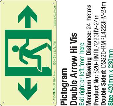
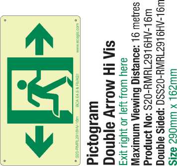
NAENAE COLLEGE
|
DRAWINGS | ||
|
SHEET NO. |
DRAWING |
SCALE |
|
A000 |
PROJECT PAGE |
1:150 |
|
A001 |
PROJECT NOTES |
NA |
|
A100 |
SITE PLAN |
As shown |
|
A101 |
EXISTING FLOOR PLAN SHOWING DEMOLITION |
1:125 |
|
A102 |
PROPOSED FLOOR PLAN WITH DIMENSIONS |
1:125 |
|
A103 |
PROPOSED FLOOR PLAN WITH WALL COVERINGS |
1:125 |
|
A104 |
PROPOSED FLOOR PLAN AND FLOOR COVERINGS |
1:200 |
|
A105 |
LINTEL PLAN |
1:125 |
|
A106 |
REFLECTED CEILING PLAN |
1:100 |
|
A200 |
INTERIOR CROSS SECTIONS |
1:50 |
|
A201 |
INTERIOR CROSS-SECTIONS |
1:50 |
|
A202 |
INTERIOR CROSS-SECTIONS |
1:50 |
|
A203 |
INTERIOR CROSS-SECTIONS |
1:50 |
|
A204 |
INTERIOR CROSS-SECTIONS |
1:50 |
|
A205 |
INTERIOR ELEVATIONS OF ADMIN/RECEPTION |
1:50 |
|
A206 |
INTERIOR ELEVATIONS OF MEETING ROOM |
1:35 |
|
A207 |
INTERIOR ELEVATIONS OF TOILETS |
1:25 |
|
A208 |
ALUMINIUM INTERIOR PARTITIONS |
1:25 |
|
A209 |
ALUMINIUM INTERIOR PARTITIONS |
1:25 |
|
A210 |
ALUMINIUM INTERIOR PARTITIONS |
1:25 |
|
A211 |
ALUMINIUM INTERIOR PARTITIONS - DETAILS |
As shown |
|
A212 |
ALUMINIUM INTERIOR PARTITIONS - DETAILS |
As shown |
|
A213 |
ALUMINIUM INTERIOR PARTITIONS - DETAILS |
As shown |
|
A214 |
DOOR SCHEDULE |
1:50 |
|
A300 |
PLUMBING AND DRAINAGE |
1:125 |
|
A301 |
ELECTRICAL AND LIGHTING |
1:100 |
|
A400 |
LINTEL AND JOIST DETAIL ACROSS HALLWAY |
As shown |
|
A401 |
INTERIOR JOINERY - RECEPTION COUNTER |
1:25 |
|
A402 |
INTERIOR JOINERY - RECEPTION COUNTER |
1:25 |
|
A403 |
INTERIOR JOINERY - RECEPTION COUNTER |
1:25 |
|
A404 |
INTERIOR JOINERY - KITCHEN AND SICK BAY |
1:20 |
|
A405 |
FRAMELESS SLIDING WINDOWS |
NA |
|
A406 |
FRAMELESS SLIDING WINDOWS |
NA |
|
A407 |
PHONIC CEILING TILES |
NA |
|
A408 |
ZENTHE TIMBER SCREEN |
NA |
|
A409 |
ZENTHE TIMBER SCREEN |
NA |
|
A410 |
FRAMING DETAIL |
1:5 |
PROJECT NAME
INTERIOR UPGRADE OF ADMINISTRATION BLOCK
ADDRESS
910 HIGH STREET
AVALON
LOWER HUTT 5011
PROJECT STATUS
TENDER/CONSENT DRAWINGS
DATE
AUGUST 2022
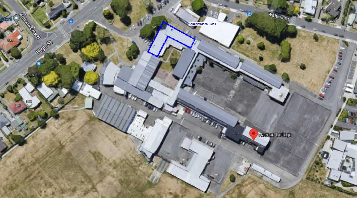
IR GROUP
PLAN DESIGN DELIVER
PROJECT NOTES
TIMBER FRAMING
Interior timber framed walls below 3m in height SG8 H1.2 90x45 studs @ 600crs with dwangs @ 800crs. For interior walls higher than 3m, H1.2 90X45 studs @ 400crs with dwangs @ 800crs
All trimming studs to comply with NZS 3604:2011 Clause 8.5.2.1 unless specified otherwise
Fixings and Fastenings
All fixings and fastenings to be suitable for Exposure Zone C as outlined in NZS3604:2011 Table 4.1.
The nailing schedule for timber framing is to comply with NZS3604:2011 Table 8.19.
Top Plates (H1.2)
Load-bearing walls (interior) 2/90x45mm
Non-load bearing walls 90x45mm
Bottom Plates (H3.2)
All interior walls 90x45mm
Holes and checks in top plates shall not exceed those as shown in NZS3604:2011 Figures 8.19 and 8.20
Bottom Plate Fixing
Requirements for the fixing of bottom plates of external and internal walls to suspended timber floor is given in NZS 3604:2011 Table 8.19. The specifications are:
-
• Hand-driven nails to external walls and internal wall bracing elements -
2 x 100 x 3.75mm nails @ 600crs max.
-
• Hand-driven nails to unbraced internal walls - 1 x 100 x 3.75mm nail
@ 600crs max.
-
• Power-driven nails to external walls and internal wall bracing element -
3 x 90 x 3.15mm nail @ 600crs max.
-
• Power-driven nails to unbraced internal walls - 1 x 90 x 3.15mm nail @
600crs max.
Depending on the capacity of bracing within walls, the manufacturer of the bracing system may specify different fixings to those above. The max. bracing capacity for walls fixed to timber-framed floors under NZS3604:2011 is 120BU/m.
The Ministry of Education requires that galvanised steel fixings (nails, bolts, plates etc.) in contact with timber treated with copper-bearing preservatives are NOT to be used
SED BEAMS AND WALL BRACING
Beams and Wall Bracing have been SED. Refer to accompanying
Engineer's documentation for calculations, designs and specifications for beams and wall bracing
INTERIOR
Final measurements for all finishes to be checked and confirmed on site by the contractor
Flooring
-
• Infill floors in existing toilet areas to make level with adjacent floors
-
• Level floor and prepare for installation of new carpet tiles and vinyl sheeting as indicated on sheet A104
Wall Lining
-
• Existing wall coverings and wall linings removed and disposed of, and walls prepared for new wall linings
-
• Line existing and new walls with 10mm GIB plasterboard (Aqualine to wet areas) stopped for level 4 paint finish (unless otherwise
indicated). Refer to Engineer's Bracing Plan for specialist wall linings and requirements
-
• Autex Composition (in selected colours) over 10mm GIB on new and existing walls - see interior elevations
-
• Resene paint (in selected colours) on new and existing walls - see interior elevations
-
• Plytech Ambience Poplar clear coated (2440x1220x12mm) on new and existing walls - see interior elevations
-
• Wall linings adjacent to appliances and facilities shall have surfaces that can be easily maintained in a hygienic condition and
comply with NZBC G3 Clause 1.6.
Ceiling Lining
-
• Option One: Existing ceiling linings removed and disposed of, and 13mm GIB ceiling lining on existing ceiling battens. Stopped
for level 4 paint finish. Paint in Resene Ceiling White - refer to Reflected Ceiling Plan
-
• Option Two: T+ R Interiors Phonic (C Max) Direct Fix ceiling tiles (1200x600) fixed directly to existing ceiling lining with an
aluminium angle along ceiling edges - refer to Reflected Ceiling Plan
Interior Doors
-
• All internal door leaf widths as noted on floor plan.
-
• All single door heights 1980mm unless noted otherwise in Door Schedule.
-
• All double door heights 2000mm unless noted otherwise in Door Schedule
-
• Paint quality doors or powdercoated aluminium frames - see Door Schedule
-
• Allow to paint existing timber doors and frames
Frameless sliding windows (Admin/reception)
-
• Supply and install Hafele track system for frameless sliding glass windows in reception/admin
-
• 6mm glass supplied to suit Hafele track system for each sliding glass window
Interior Aluminium Partition Suite
-
• Supply and install T+R Interiors Eclipse 64mm aluminium suite as detailed in the drawings
Interior trim
-
• Supply and install interior trim (skirting, scotia and architraves)
Skirting: SPP SA135x18
Architraves: SPP SA85x18
Scotia: SPP Scotia SC35
-
• Allow to paint in selected Resene colour
Interior Joinery
-
• Supply and install kitchen cabinetry and benchtops, vanity unit in sick bay, reception counters and cabinetry in Admin Office
Sanitary Fixtures
-
• Supply and install all sanitary fixtures and accessories in the 3 new WC's
Mechanical Ventilation (WC1 to WC3)
-
• Supply and install mechanical ventilation system as designed and specified by Simx. See details in specifications
Lighting
-
• Supply and install ceiling mounted LED battens and recessed LED ceiling lights as indicated on the Electrical and Lighting Plan
Heating
-
• Supply and install ceiling mounted EnergoCassette radiant heaters (ENC300 and ENC600) as indicated on the Reflected Ceiling
Plan
Server, fibre and cables
-
• Allow to relocate existing server, data, fibre and cables
CLIENT
NAENAE COLLEGE
|
PROJECT |
ADDRESS |
STATUS |
DRAWING |
|
INTERIOR UPGRADE OF ADMINISTRATION BLOCK |
910 HIGH STREET AVALON LOWER HUTT 5011 |
TENDER/CONSENT DRAWINGS |
PROJECT NOTES |
Sheet No. A001
Scale 1 : 1 @ A3
Date AUGUST 2022
Drawn By JANINE FENELON
This design and drawing is the copyright of IR Group Ltd and is not to be reproduced without written permission.
Do not scale from drawings.
LOCATION PLAN 1:200
SITE PLAN
1:1000
1
2
3
4
5
6
7
8
YA
12
20
13
14
11
10
15
16
17
9
19
18
LEGAL DESCRIPTION
Lots 1 and 2, DP 18397
Part Lot 1, DP 19671
SITE DESCRIPTION
|
SNU XA | |
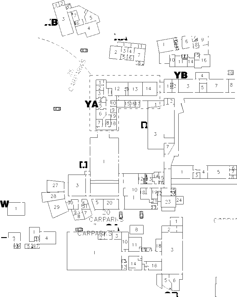
X R M |
10 9 12 |
|
Z8 GB | |

9r
|
YC | |
|
1 | 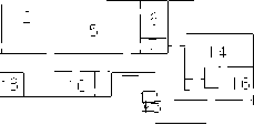 |
|
1517 | |
3 GA
YF
2 J .
1
2
3
5
6
12
YECARP5ARKS
|
C2ARPARKS |
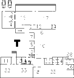 |
VS

Exposure Zone C
Earthquake Zone 3
Wind Zone Very High
|
!R GROUP |
CLIENT |
PROJECT |
ADDRESS |
STATUS |
DRAWING |
Sheet No. |
A100 |
This design and drawing is the copyright of IR Group Ltd and is |
|
NAENAE COLLEGE |
INTERIOR UPGRADE OF |
910 HIGH STREET |
TENDER/CONSENT |
SITE PLAN |
Scale |
As indicated @ A3 |
not to be reproduced without | |
|
PLAN DESIGN DELIVER |
ADMINISTRATION BLOCK |
AVALON |
DRAWINGS |
Date |
written permission. | |||
|
janine@irgroup.co.nz 027 6222 138 |
LOWER HUTT 5011 |
AUGUST 2022 |
Do not scale from drawings. | |||||
|
716 Main Road North, Upper Hutt |
Drawn By |
JANINE FENELON |
7343
2128
3455
|
TEACHING |
DEMOLITION

 |
|
EXD29 |
MEDICAL
00
Allow to demolish, remove and dispose of all components shown in dashed red lines - interior walls, doors, windows, fixtures and fittings School to salvage any specific items prior to demolition and construction commencing
Remove existing wall linings (ply and plasterboard) and prepare for new wall linings
Remove nominated ceiling linings and prepare for new GIB ceiling linings (refer to Reflected ceiling plan)
Uplift existing flooring throughout and prepare floors for new floor coverings - carpet tiles and vinyl. Allow to infill existing drains and waste pipes
Allow to isolate, disconnect and make good all services for demolition
Remove light fittings, pin boards, fixtures and fittings and consult with school regarding re-use or retention
Remove all existing radiator heaters, hot water cylinders and heat pumps and consult with school regarding re-use or retention
Allow to relocate electrical, data and security components
 |
5245 |
|
RAMP STORAGE 2840 5615 DN DN DECK EXW17 OFFICE MEETING |
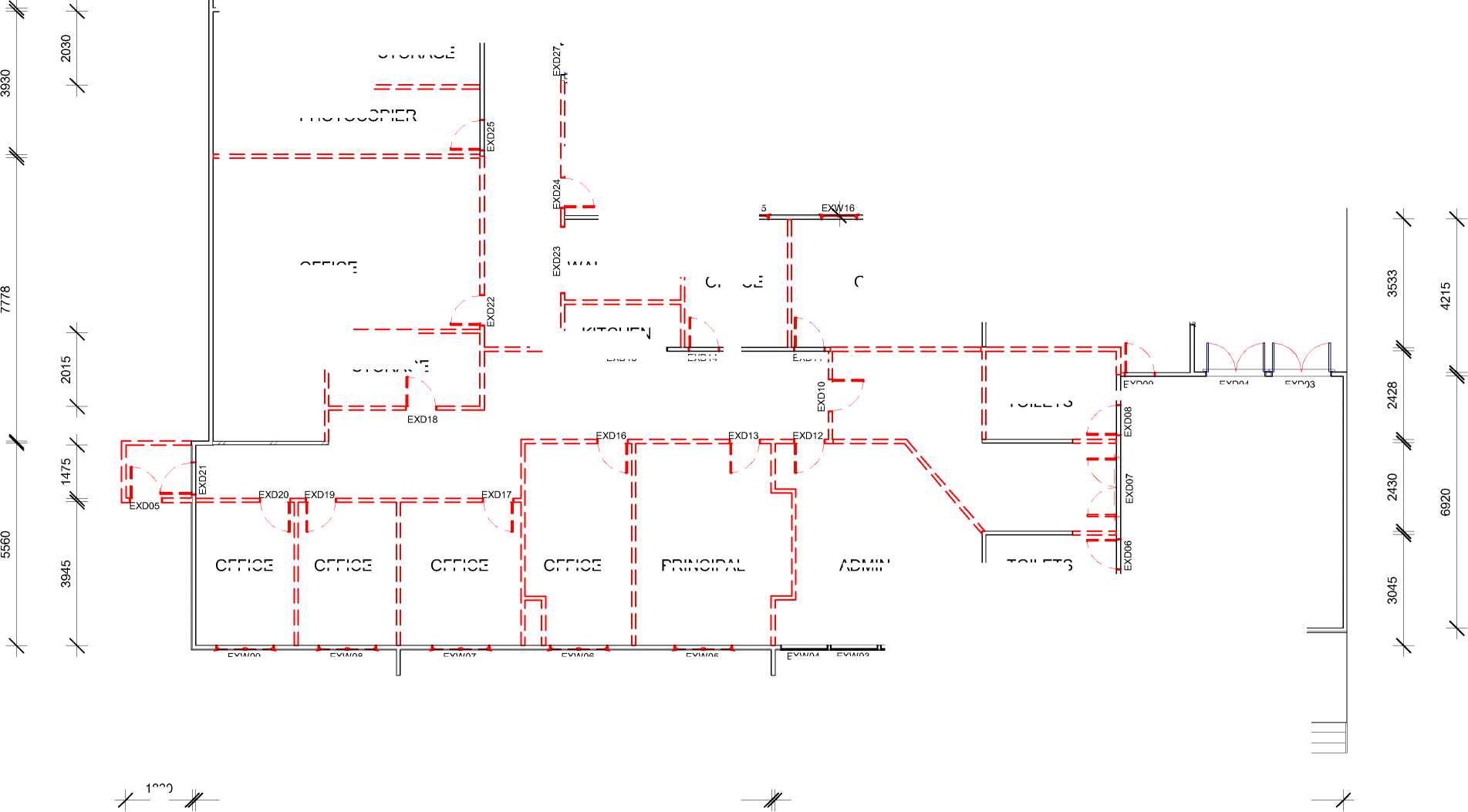
PHOTOCOPIER EXD11 EXD18 OFFICE OFFICE OFFICE OFFICE PRINCIPAL ADMIN 1830 |
|
EXD04 HALL FOYER TOILETS EXD01 EXD02 pro EXW09 EXW08 EXW07 EXW06 EXW05 DECK DN RAMP 2715 2715 3325 2950 3735 5695 3597 6128 EXW04 EXW03 EXW02 EXW01 |
OFFICE
STORAGE
!R GRWP
CLIENT
PROJECT
PLAN DESIGN DELIVER
NAENAE COLLEGE
|
SICK BAY | |
II OFFICE
IL
 |
EXW15 |
WAITING AREA
OFFICE

KITCHEN
EXD15
EXD14
TOILETS
EXD09
EXD03
ADDRESS
STATUS
DRAWING
Sheet No.
A101
INTERIOR UPGRADE OF
ADMINISTRATION BLOCK
910 HIGH STREET
AVALON
LOWER HUTT 5011
TENDER/CONSENT DRAWINGS
EXISTING FLOOR PLAN SHOWING DEMOLITION
Scale
Date
Drawn By
1 : 125 @ A3
AUGUST 2022
JANINE FENELON
This design and drawing is the copyright of IR Group Ltd and is not to be reproduced without written permission.
Do not scale from drawings.

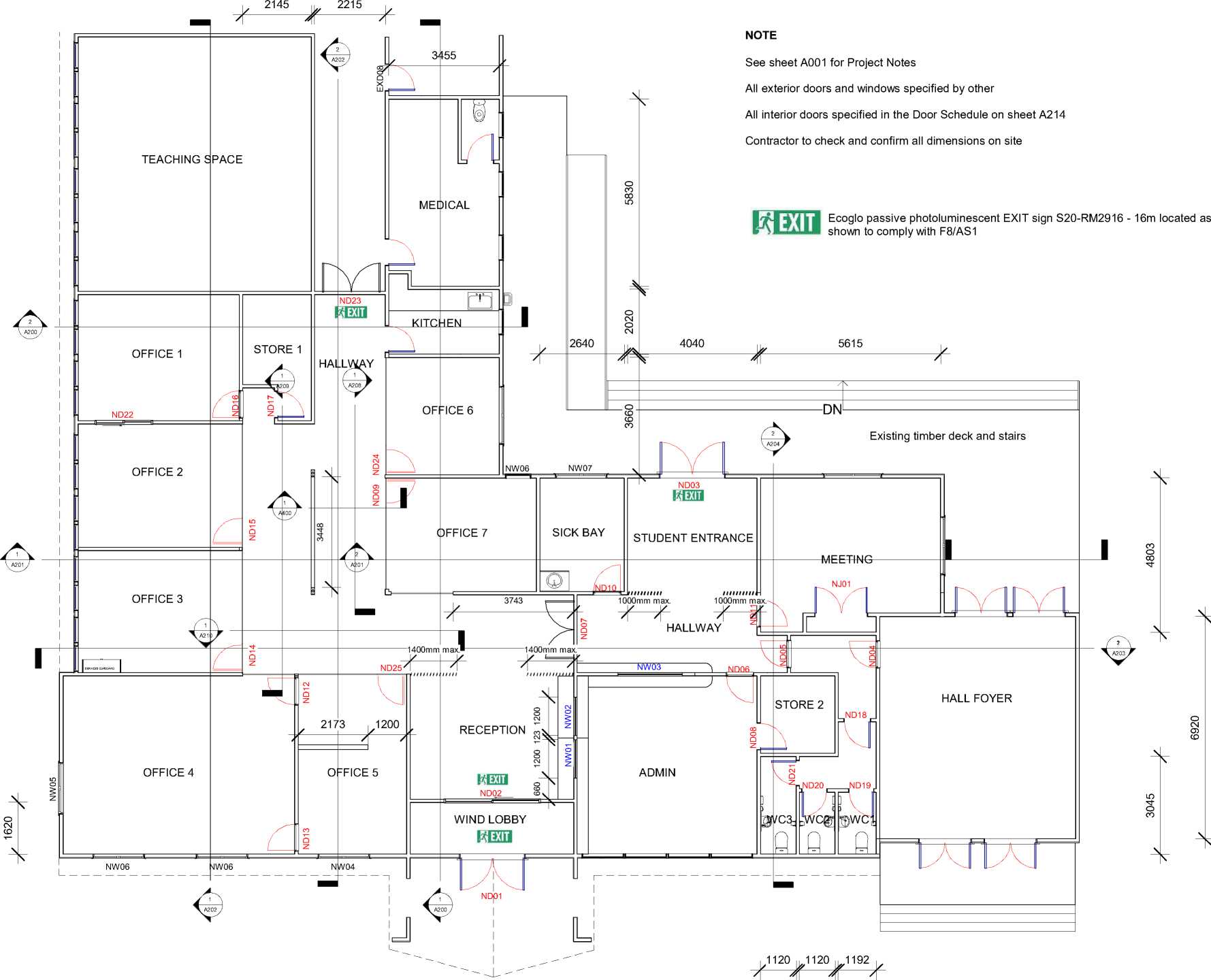 |
|
6113 7213 3393 5100 5610 3612 |
|
CLIENT |
PROJECT |
ADDRESS |
STATUS |
DRAWING |
Sheet No. |
A102 |
|
NAENAE COLLEGE |
INTERIOR UPGRADE OF ADMINISTRATION BLOCK |
910 HIGH STREET AVALON LOWER HUTT 5011 |
TENDER/CONSENT DRAWINGS |
PROPOSED FLOOR PLAN WITH DIMENSIONS |
Scale Date Drawn By |
1 : 125 @ A3 AUGUST 2022 JANINE FENELON |
ELEVATION INDICATOR
This design and drawing is the copyright of IR Group Ltd and is not to be reproduced without written permission.
Do not scale from drawings.
IR GRWP
PLAN DESIGN DELIVER
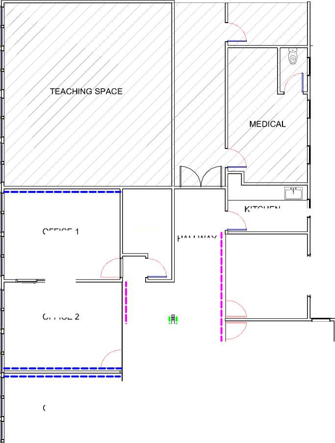 |
OFFICE 6 SICK BAY |
|
HALLWAY OFFICE 7 OFFICE 3 FEATURE WALL #2 SERVICES CUPBOARD | |
OFFICE 1
OFFICE 2

FEATURE WALL #1
KITCHEN
WALL LININGS
Autex Composition - colours to be selected
4 Feature Walls created with Autex - Designs to be confirmed
Plytech Ambience Poplar clear coated 2440x1220x12mm
T+R Interiors Eclipse 64mm Aluminium Suite
Non-structural screen created with timber battens
All other interior walls to be painted in selected Resene colours
No interior work in the hatched areas

OFFICE 4
CLIENT
NAENAE COLLEGE
|
MEETING |
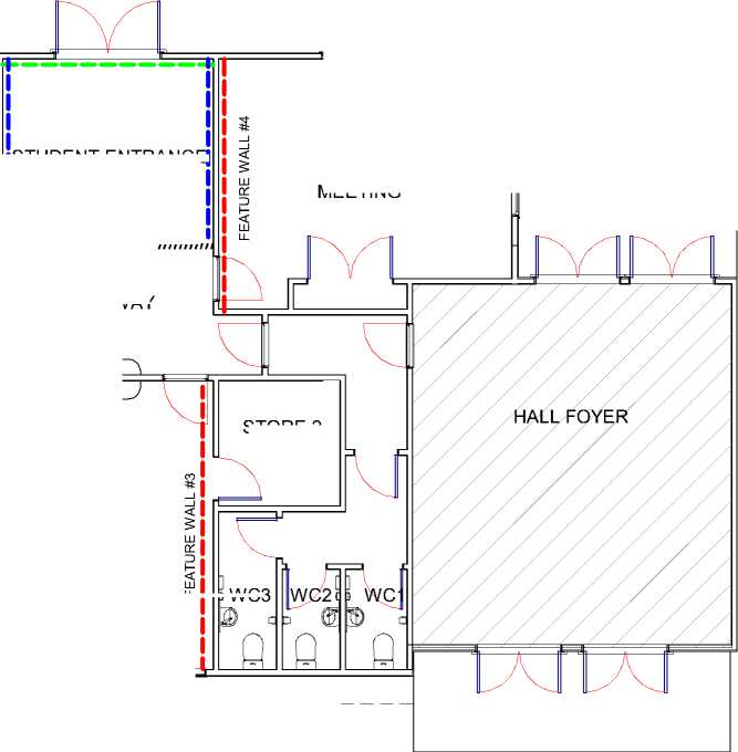
If I fl fl fit» WC3 |
|
ADMIN |
STUDENT ENTRANCE
|
OFFICE 5 |
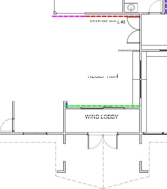
WIND LOBBY |
HALLWAY

STORE 2
RECEPTION
PROJECT
ADDRESS
STATUS
DRAWING
INTERIOR UPGRADE OF
ADMINISTRATION BLOCK
910 HIGH STREET
AVALON
LOWER HUTT 5011
TENDER/CONSENT DRAWINGS

Sheet No.
A103
PROPOSED FLOOR PLAN WITH WALL COVERINGS
Scale
Date
Drawn By
1 : 125 @ A3
AUGUST 2022
JANINE FENELON
This design and drawing is the copyright of IR Group Ltd and is not to be reproduced without written permission.
Do not scale from drawings.
|
TEACHING SPACE (NO CHANGES) STORE | |
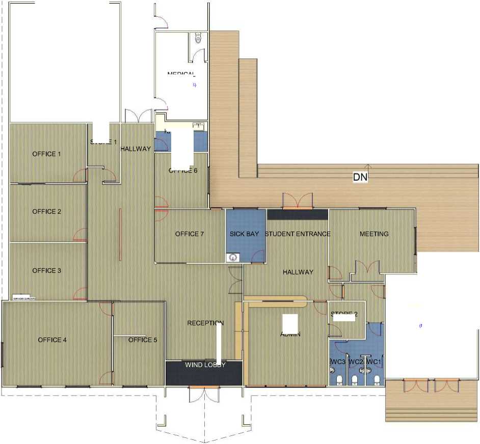
OFFICE 1 OFFICE OFFICE 2 OFFICE 7 SICK BAY STUDENT ENTRANCE MEETING OFFICE 3 HALLWAY RECEPTION ADMIN OFFICE 4 OFFICE 5 WIND LOBBY |
wn (NO CHANGES) |
MEDICAL
(NO CHANGES)
KITCHEN
STORE 2
EXISTING TIMBER DECKING - NO CHANGES TO BE MADE
SHEET VINYL -TO BE SELECTED
ADVANCED FLOORING GOLD COAST 04
AND GOLD COAST 05 LAID IN HERRINGBONE PATTERN IN RECEPTION, HALLWAYS, STUDENT ENTRANCE AND ADMIN. ALL OTHER AREAS TO HAVE CARPET LAID IN AN ASHLAR PATTERN. SEE ADVANCE FLOORING PLAN BELOW
ADVANCED FLOORING EVERTREAD ENTRANCE MATTING BLUE 602
|
TEACHING SPACE |
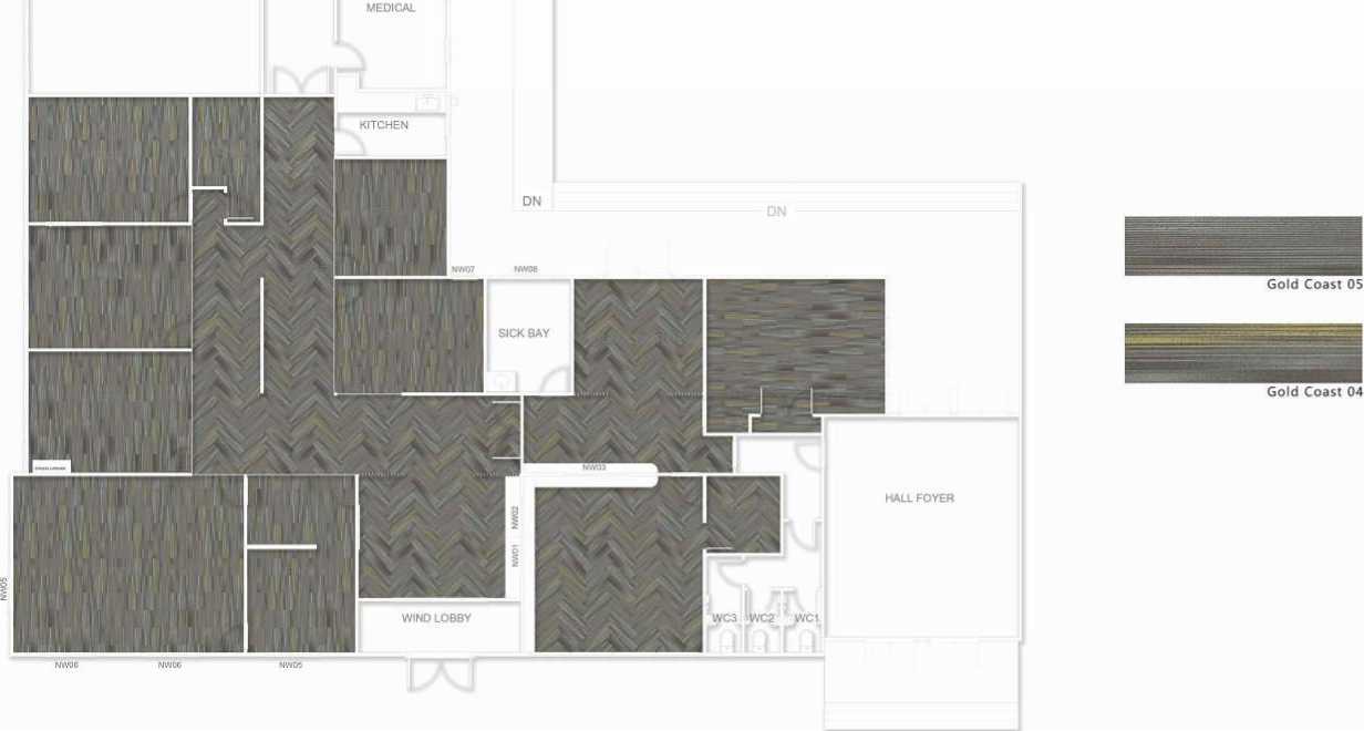 |
|
A Advance FLOORING SYSTEMS |
Please Note: Tn» Illustration is »or reference only |
Phone: 09 634 4455 |
Option: 0715 |
Project |
Naenae College Admin Upgrade Project | ||||
|
Finished quantities and sites to be confirmed with on-site measure For the most accurate representation of colours. please view on a screen. Printing may reduce the clarity and cotour accuracy. |
Email: | ||||||||
|
!R GR^UP PLAN DESIGN DELIVER 027 6222 138 716 Main Road North, Upper Hutt |
CLIENT NAENAE COLLEGE |
PROJECT INTERIOR UPGRADE OF ADMINISTRATION BLOCK |
ADDRESS 910 HIGH STREET AVALON LOWER HUTT 5011 |
STATUS TENDER/CONSENT DRAWINGS |
DRAWING PROPOSED FLOOR PLAN AND FLOOR COVERINGS |
Sheet No. Scale Date Drawn By |
A104 1 : 200 @ A3 AUGUST 2022 JANINE FENELON |
This design and drawing is the copyright of IR Group Ltd and is not to be reproduced without written permission. Do not scale from drawings. | |
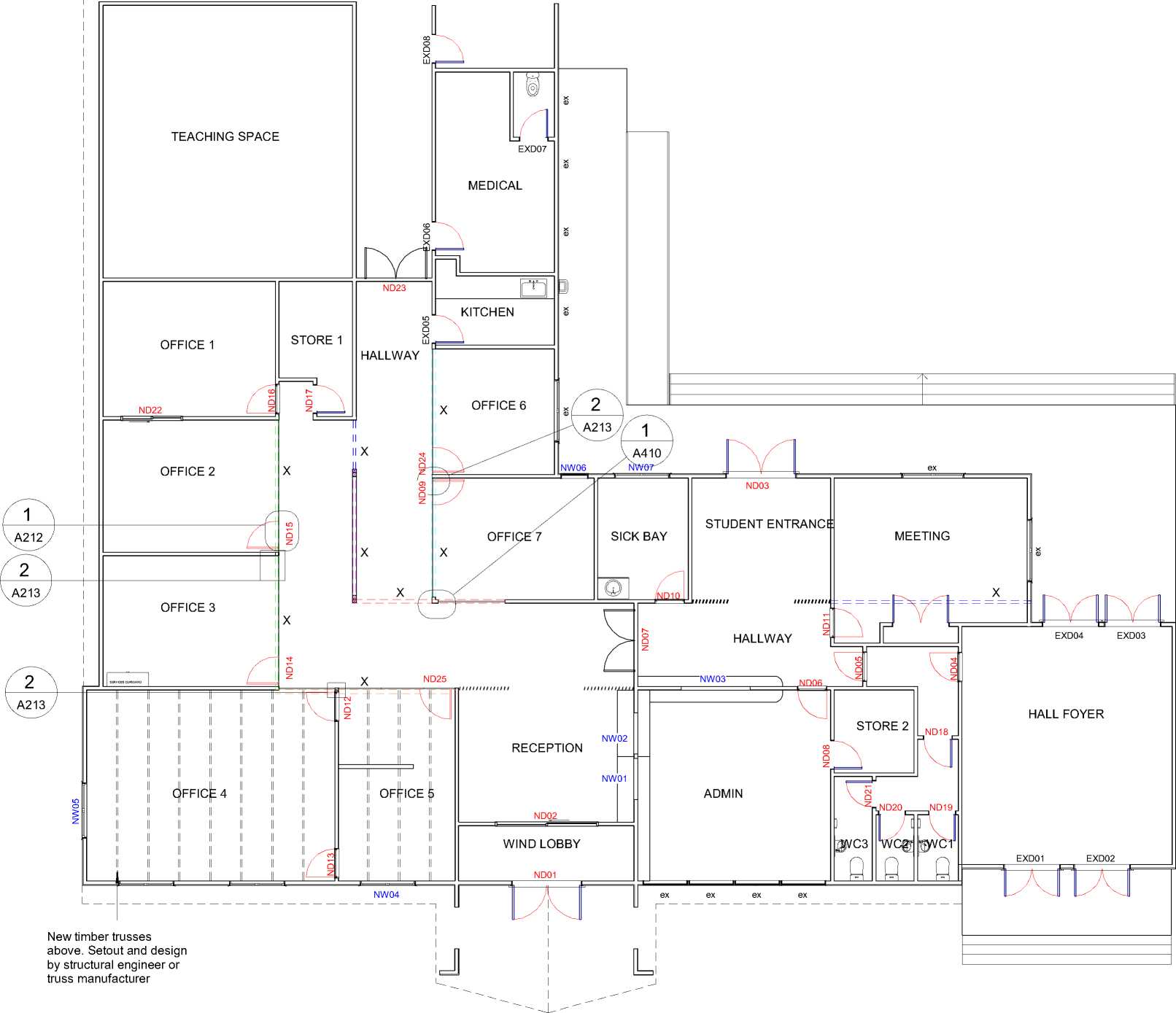
BEAMS
All beams shown on drawings (X) have been specified by Structural Engineer. Refer to the accompanying Engineer's Beam Plan
LINTELS
Lintels are only specified for INTERIOR doors and windows. Exterior door and window lintels specified by ANOTHER
Lintels shall be provided over all openings in loadbearing walls.
Lintels shall be of the dimensions given by Tables 8.9 in NZS3604:2011.
All lintels to be H1.2 SG8 unless noted otherwise.Uplift fixings noted on Lintel
Plan as per attached Lumberlok options:
Type E - 1.4 kN
Type F - 4.0 kN
Type G - 7.5 kN
Type H - 13.5 kN
Refer to manufacturer's specifications for specified fixings and fasteners for lintels
|
DOOR LINTELS | |||||||||||||||||||||||||||
| |||||||||||||||||||||||||||
|
WINDOW LINTELS | |||||||||||||||
| |||||||||||||||
|
CLIENT |
PROJECT |
ADDRESS |
STATUS |
DRAWING |
Sheet No. |
A105 |
This design and drawing is the copyright of IR Group Ltd and is |
|
NAENAE COLLEGE |
INTERIOR UPGRADE OF ADMINISTRATION BLOCK |
910 HIGH STREET AVALON LOWER HUTT 5011 |
TENDER/CONSENT DRAWINGS |
LINTEL PLAN |
Scale Date Drawn By |
1 : 125 @ A3 AUGUST 2022 JANINE FENELON |
not to be reproduced without written permission. Do not scale from drawings. |
EXISTING CEILING HEIGHTS
NOTE
PROPOSED CEILING HEIGHTS
Ceiling height to be 3200mm. Existing ceiling linings to be replaced with new 13mm GIB on 70x35 timber battens or GIB Rondo battens.
Each colour represents a different existing ceiling height
Ceiling heights to be maintained and ceiling linings to be retained. Replace or repair if damaged during construction and paint in Resene Ceiling White
Ceiling height to be maintained and ceiling linings to be retained. Replace or repair if damaged during construction and paint in Resene Ceiling White
Ceiling height to be 2400mm. New 13mm GIB ceiling linings on 70x35 timber battens or GIB Rondo battens. Paint in Resene Ceiling White for Kitchens and Bathrooms
Ceiling heights in transition areas/hallway to be determined by the height of the clerestory windows (specfied by others)
Grid ceilings: T + R Interiors Phonic Ceiling Tiles 1200x600 direct fixed to GIB ceiling lining
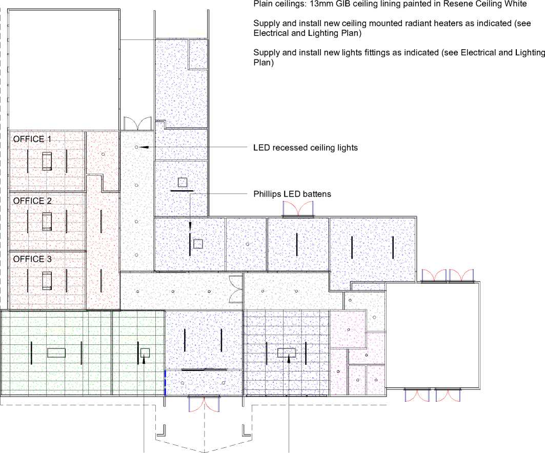 |
|
EnergoCassette ENC300 EnergoCassette ENC600 |
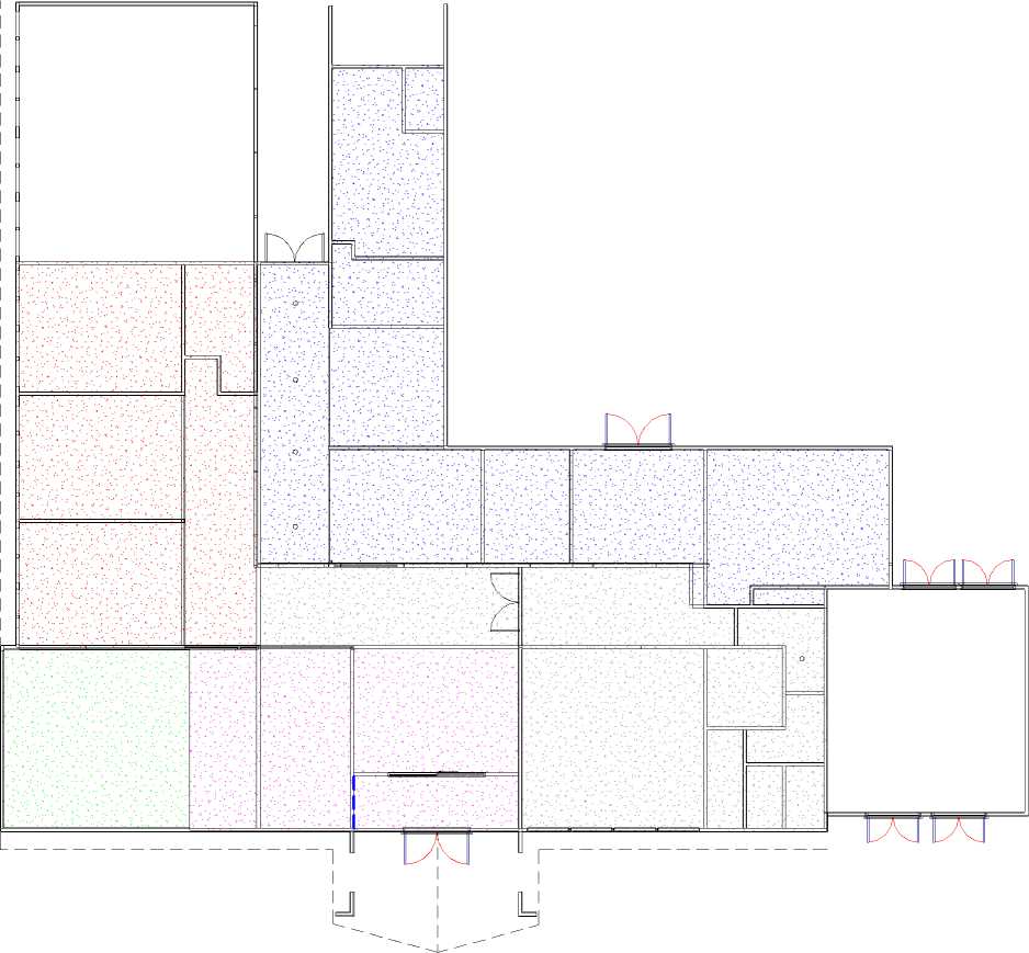
| ||||||||||||||||
|
716 Main Road North, Upper Hutt |
|
STATUS |
DRAWING |
Sheet No. |
A106 |
This design and drawing is the copyright of IR Group Ltd and is |
|
TENDER/CONSENT |
REFLECTED CEILING |
Scale |
1 : 200 @ A3 |
not to be reproduced without |
|
DRAWINGS |
PLAN |
Date Drawn By |
AUGUST 2022 JANINE FENELON |
written permission. Do not scale from drawings. |
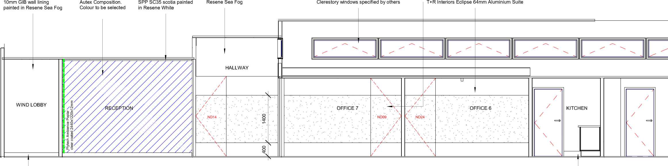
SPP SA135x18 skirting painted in Resene Eighth Tapa
Selected vinyl coved 150mm up wall with capping
SECTION A200/2
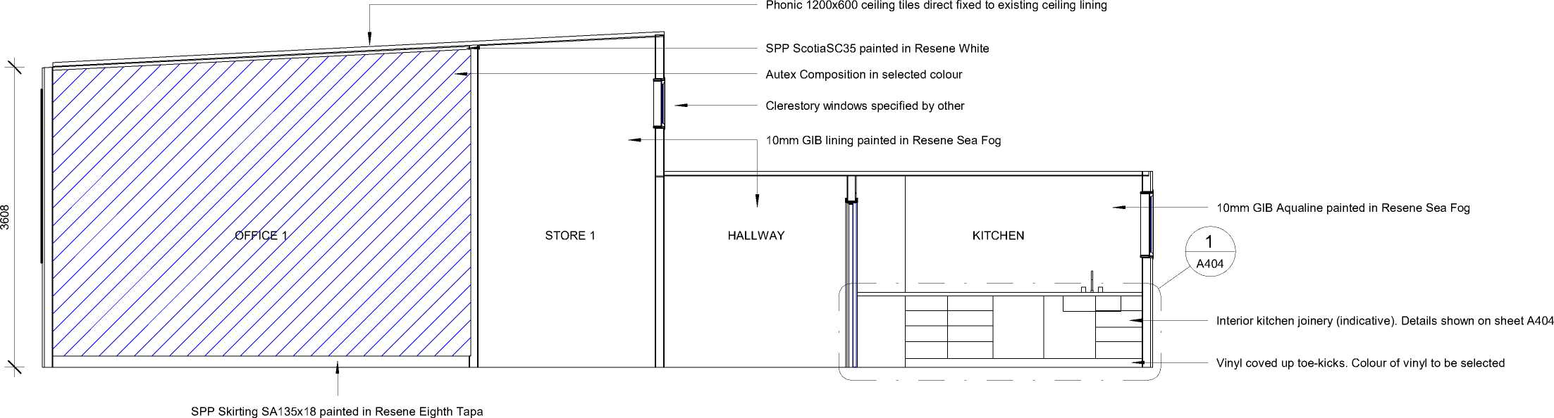
|
!R GRWP |
CLIENT |
PROJECT |
ADDRESS |
STATUS |
DRAWING |
Sheet No. |
A200 |
This design and drawing is the copyright of IR Group Ltd and is |
|
NAENAE COLLEGE |
INTERIOR UPGRADE OF |
910 HIGH STREET |
TENDER/CONSENT |
INTERIOR CROSS |
Scale |
1 : 50 @ A3 |
not to be reproduced without | |
|
PLAN DESIGN DELIVER |
ADMINISTRATION BLOCK |
AVALON |
DRAWINGS |
SECTIONS |
Date |
written permission. | ||
|
janine@irgroup.co.nz 027 6222 138 |
LOWER HUTT 5011 |
AUGUST 2022 |
Do not scale from drawings. | |||||
|
716 Main Road North, Upper Hutt |
Drawn By |
JANINE FENELON |
|
3633 | 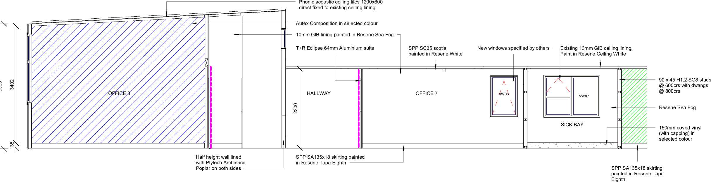 |
SECTION A201/2
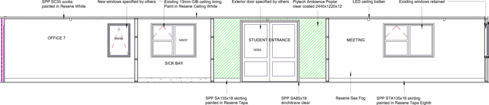 |
|
Eighth coated with Resene Aquaclear |
|
|
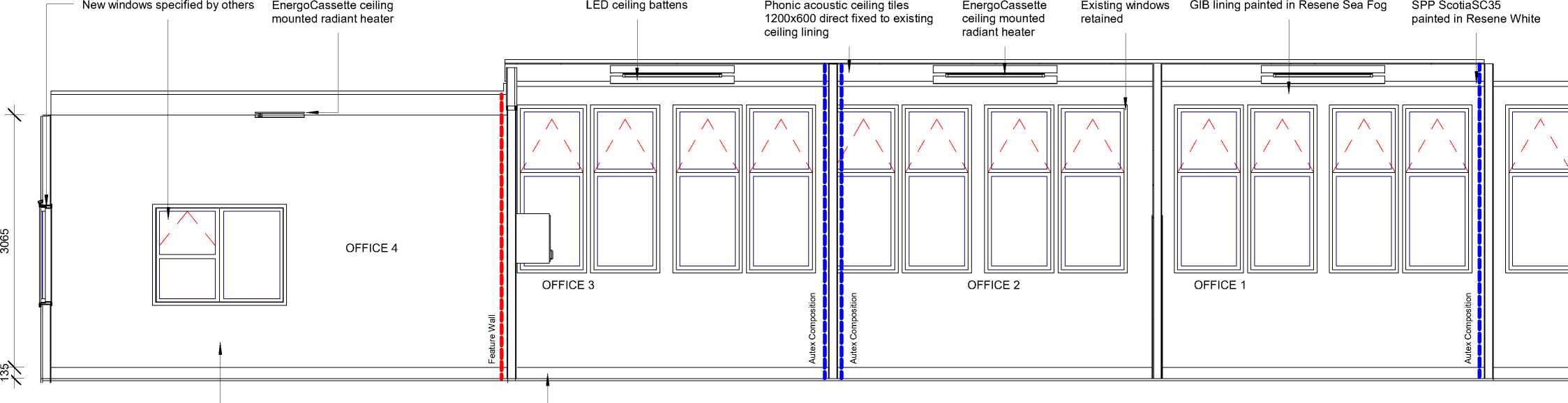 |
|
Resene Sea Fog |
SPP SA135x18 skirting painted in Resene Tapa Eighth
SECTION A202/2
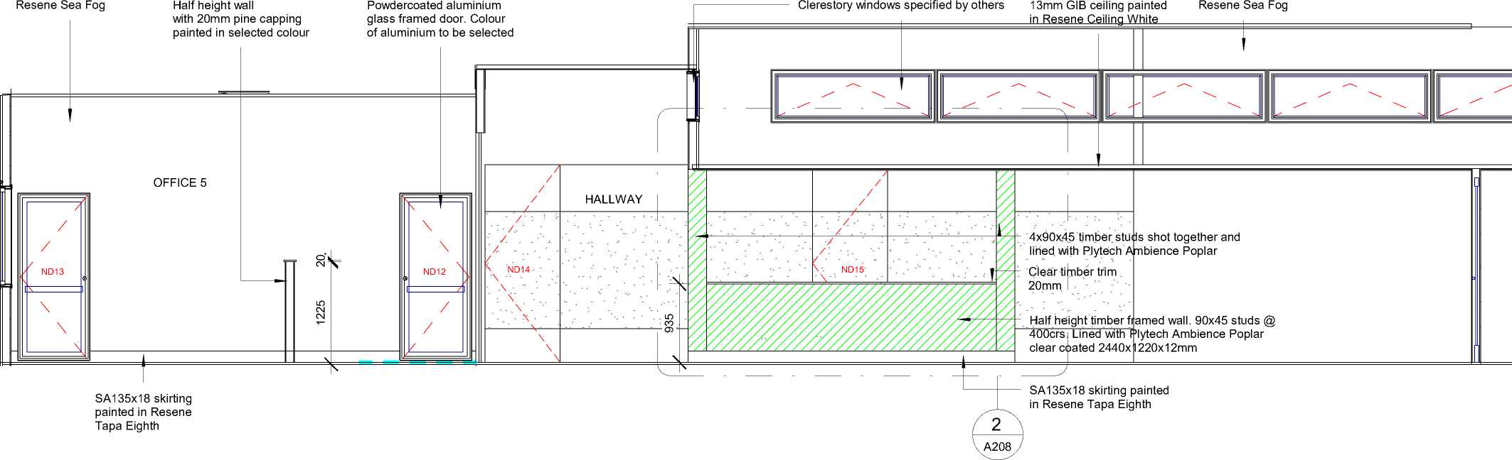
|
CLIENT |
PROJECT |
ADDRESS |
STATUS |
DRAWING |
Sheet No. |
A202 |
This design and drawing is the copyright of IR Group Ltd and is |
|
NAENAE COLLEGE |
INTERIOR UPGRADE OF ADMINISTRATION BLOCK |
910 HIGH STREET AVALON LOWER HUTT 5011 |
TENDER/CONSENT DRAWINGS |
INTERIOR CROSS-SECTIONS |
Scale Date Drawn By |
1 : 50 @ A3 AUGUST 2022 JANINE FENELON |
not to be reproduced without written permission. Do not scale from drawings. |
|
10mmGIB lining Frameless sliding window. Additional framing required Elevation of reception counter indicative. 13mm GIB ceiling on GIB T+R Interiors Eclipse 64mm |
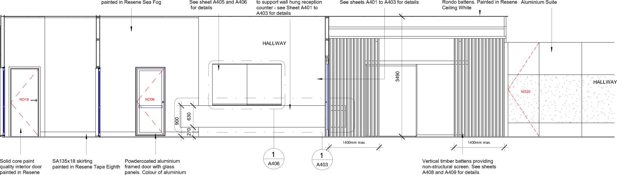 |
|
Tapa Eighth to be selected |
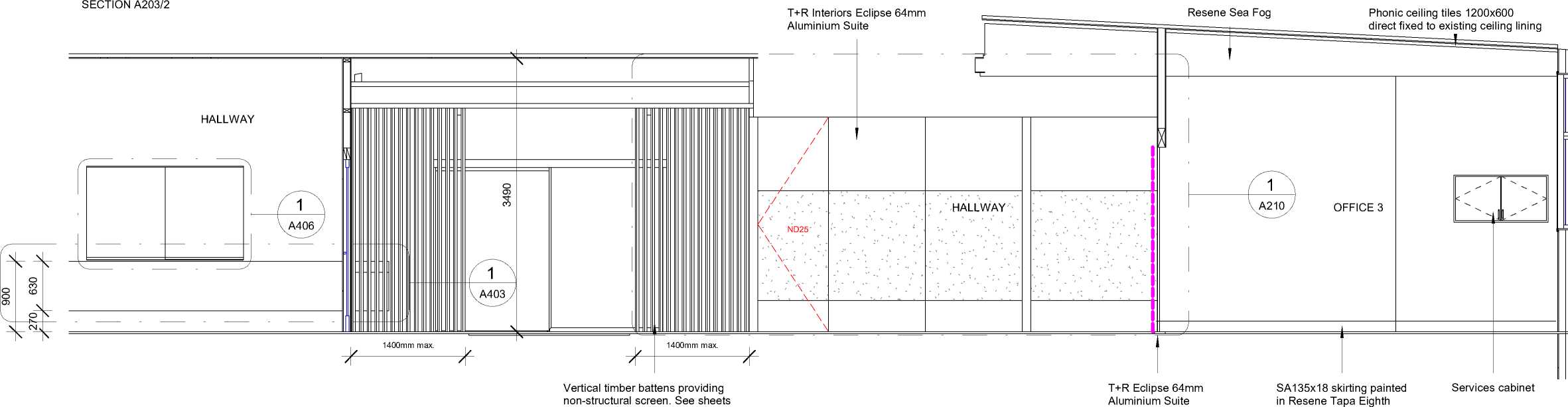 |
|
A408 and A409 for details |
|
!R GRWP |
CLIENT |
PROJECT |
ADDRESS |
STATUS |
DRAWING |
Sheet No. |
A203 |
This design and drawing is the copyright of IR Group Ltd and is |
|
NAENAE COLLEGE |
INTERIOR UPGRADE OF |
910 HIGH STREET |
TENDER/CONSENT |
INTERIOR |
Scale |
1 : 50 @ A3 |
not to be reproduced without | |
|
PLAN DESIGN DELIVER |
ADMINISTRATION BLOCK |
AVALON |
DRAWINGS |
CROSS-SECTIONS |
Date |
written permission. | ||
|
janine@irgroup.co.nz 027 6222 138 |
LOWER HUTT 5011 |
AUGUST 2022 |
Do not scale from drawings. | |||||
|
716 Main Road North, Upper Hutt |
Drawn By |
JANINE FENELON |

m
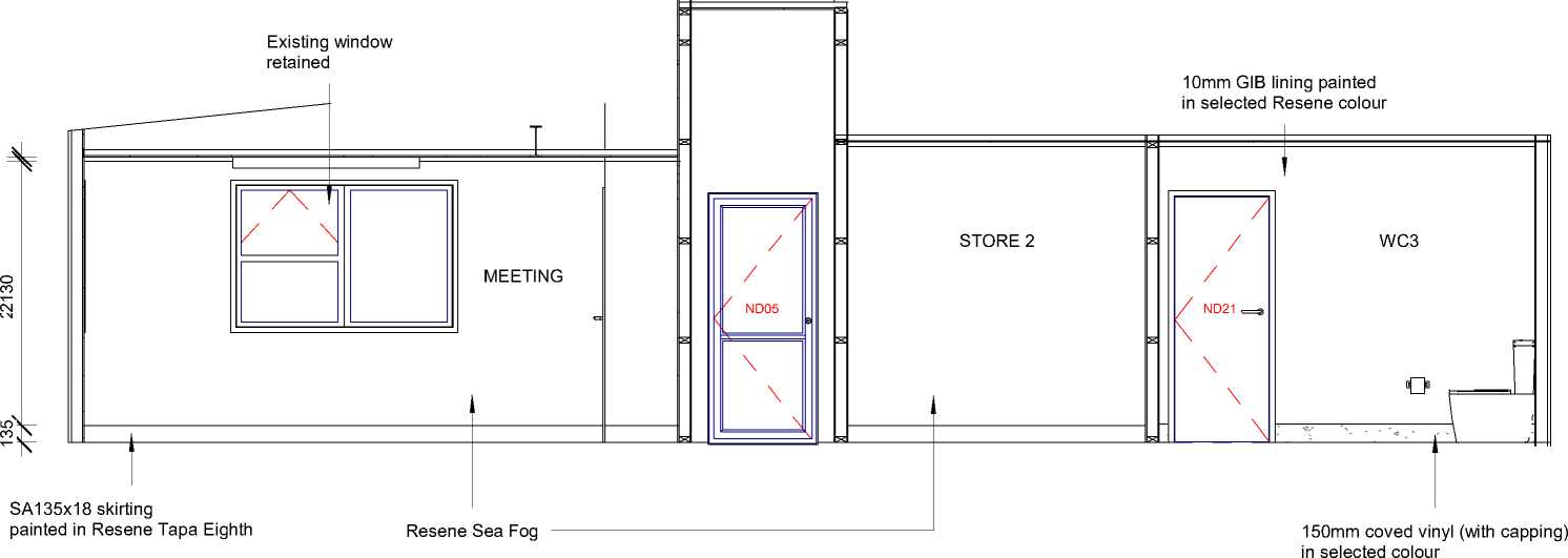
|
CLIENT |
PROJECT |
ADDRESS |
STATUS |
DRAWING |
Sheet No. |
A204 |
This design and drawing is the copyright of IR Group Ltd and is |
|
NAENAE COLLEGE |
INTERIOR UPGRADE OF ADMINISTRATION BLOCK |
910 HIGH STREET AVALON LOWER HUTT 5011 |
TENDER/CONSENT DRAWINGS |
INTERIOR CROSS-SECTIONS |
Scale Date Drawn By |
1 : 50 @ A3 AUGUST 2022 JANINE FENELON |
not to be reproduced without written permission. Do not scale from drawings. |
ELEVATION ONE
ELEVATION TWO
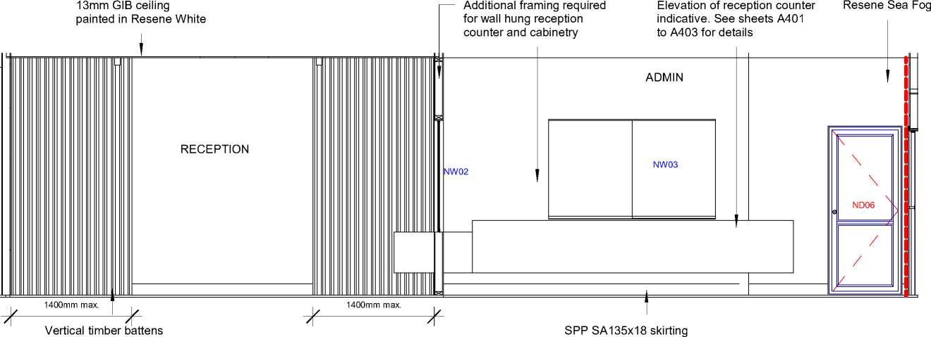 |
|
painted in Resene Eighth Tapa providing a non-structural screen. See Sheets A408 and A409 for details |
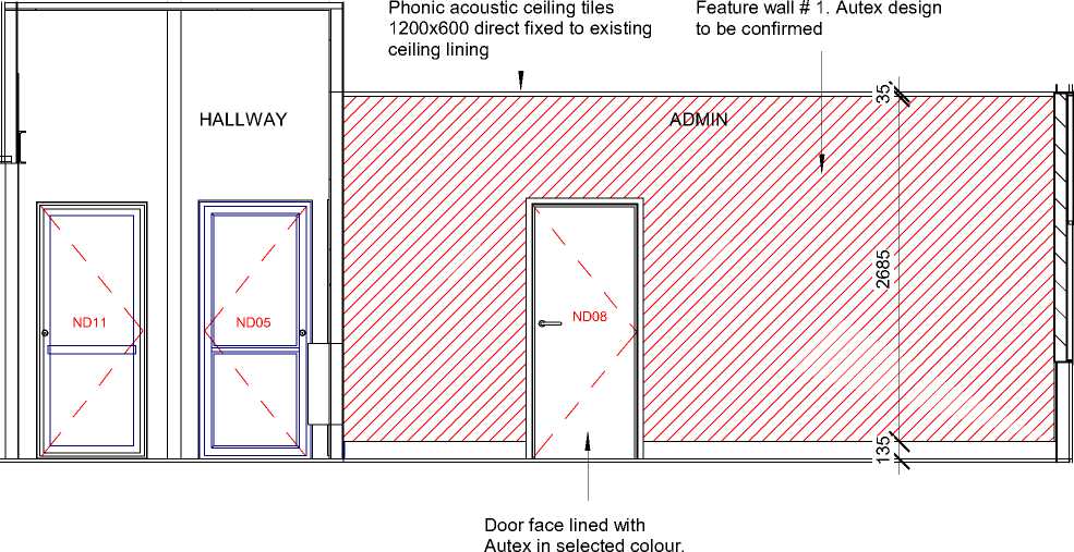 |
|
Lined door face to finish flush with Autex on wall |
ELEVATION THREE
ELEVATION FOUR
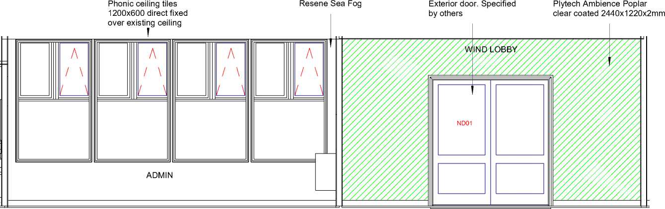
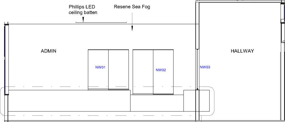

|
Drawn By JANINE FENELON |
ELEVATION ONE
ELEVATION TWO


Scotia SC35 painted in Resene White
EnergoCassette ceiling mounted radiant heater
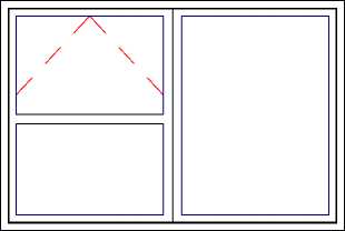
MEETING
SA135x18 skirting painted in Resene Tapa Eighth
Resene Sea Fog


|
LED ceiling batten |
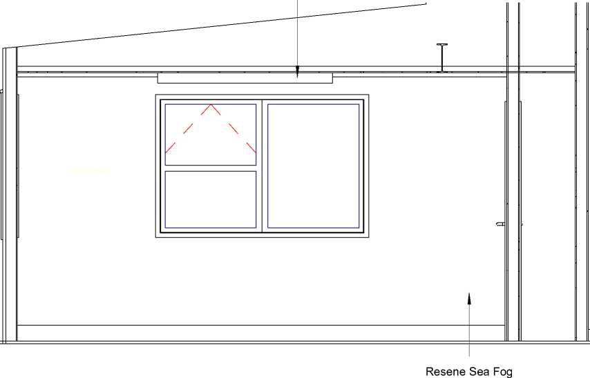 |
ELEVATION THREE
ELEVATION FOUR
Storage cupboard. Doors painted in Resene Tapa Eighth
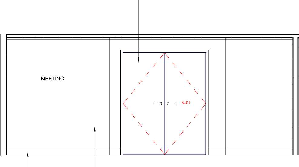 |
|
Resene Sea Fog |

Feature wall #2. Autex design to be confirmed
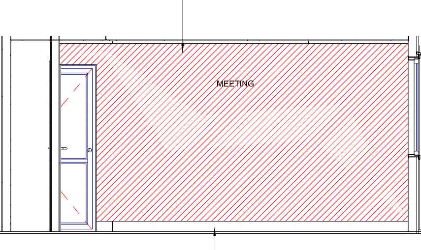
SA135x18 skirting painted in Resene Tapa Eighth
SA135x18 skirting painted in Rese Tapa Eighth
|
IR GR^UP |
CLIENT PROJECT ADDRESS STATUS DRAWING Sheet No. A206 This design and drawing is the copyright of IR Group Ltd and is NAENAE COLLEGE INTERIOR UPGRADE OF 910 HIGH STREET TENDER/CONSENT INTERIOR ELEVATIONS Scale 1 : 35 @ A3 not to be reproduced without |
|
PLAN DESIGN DELIVER |
ADMINISTRATION BLOCK AVALON DRAWINGS OF MEETING ROOM written permission. |
|
027 6222 138 716 Main Road North, Upper Hutt |
Date AUGUST 2022 LOWER HUTT 5011 Do not scale from drawings. Drawn By JANINE FENELON |

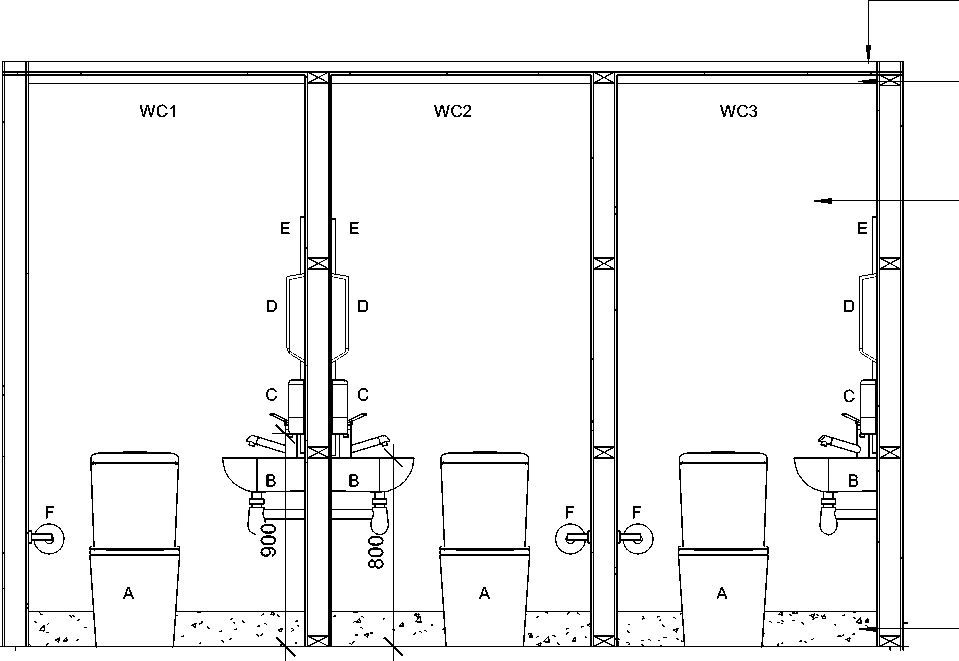 |
13mm GIB ceiling on 70x35 timber battens or GIB Rondo battens. Painted in Resene Ceiling White for Kitchens and Bathrooms Scotia SC35 painted in Resene White 10mm GIB Aqualine painted in selected Resene colour |
SANITARY WARE AND ACCESSORIES
All sanitary fixtures, dimensions and clearances are to comply with the Ministry of Education Reference Design for School Buildlings in New Zealand Toilets Version 2.0 February 2017
|
A |
Caroma Luna Cleanflush Back to Wall Suite | |
|
B |
Caroma Cosmo WHB with Methven Glide Basin Mixer | |
|
Vinyl coved 150mm up wall with |
C |
Supreme Classic Soap Dispenser (900mm above FFL) |
|
capping. Colour to be selected |
D |
Tork Paper Towel Dispenser (1200mm above FFL) |
E Frameless mirror (Top of mirror 1800mm off FFL and 600mm wide)
F Tork Twin Mini Jumbo Toilet roll dispenser
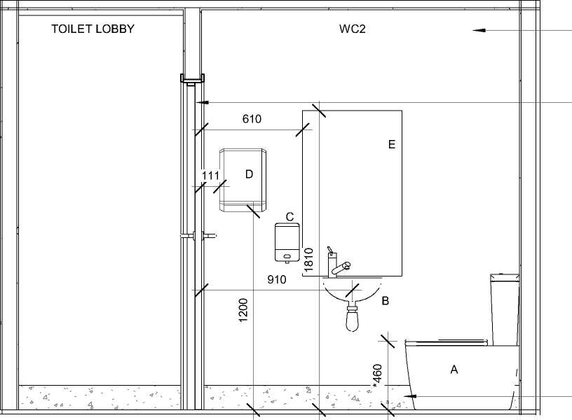 |
Vinyl coved 150mm up wall with capping. Colour to be selected 10mm GIB Aqualine painted in selected Resene colour Solid core flush faced interior door. Paint quality. Painted in selected Resene colour |
|
1920 | |
G Sanitary Bin
|
CLIENT |
PROJECT |
ADDRESS |
STATUS |
DRAWING |
Sheet No. |
A207 |
This design and drawing is the copyright of IR Group Ltd and is |
|
NAENAE COLLEGE |
INTERIOR UPGRADE OF ADMINISTRATION BLOCK |
910 HIGH STREET AVALON LOWER HUTT 5011 |
TENDER/CONSENT DRAWINGS |
INTERIOR ELEVATIONS OF TOILETS |
Scale Date Drawn By |
1 : 25 @ A3 AUGUST 2022 JANINE FENELON |
not to be reproduced without written permission. Do not scale from drawings. |

Bracing and lintel to be designed by engineer
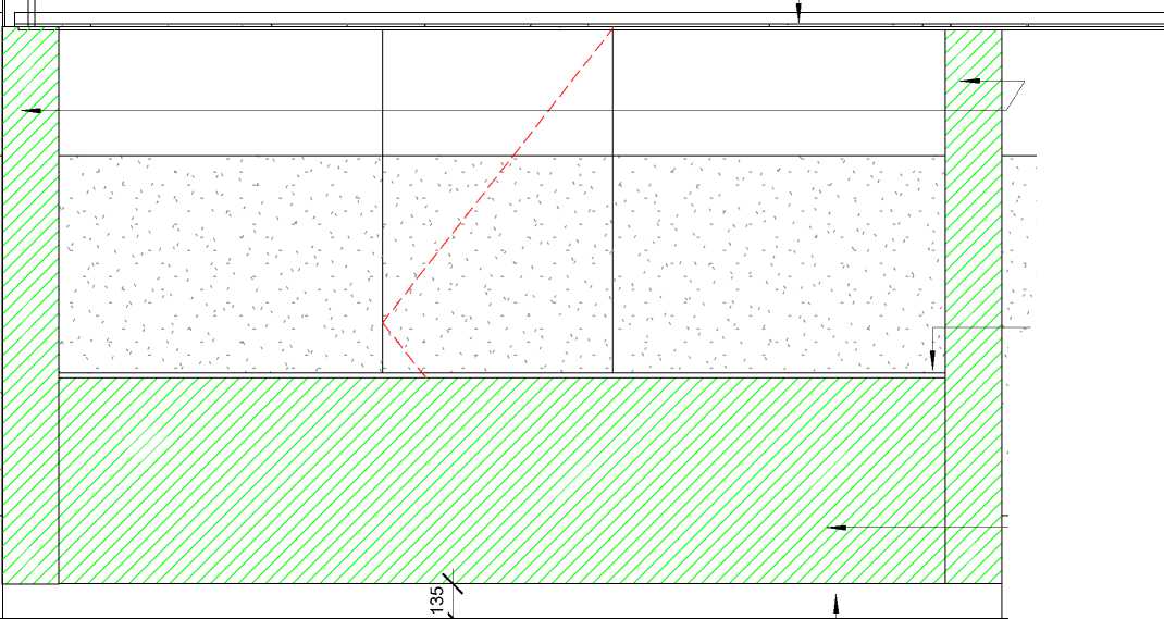 |
4 x 90x45 studs shot through and lined with Plytech Ambience Poplar Half height timber framed wall. 90x45 studs @ 400crs. Lined with Plytech Ambience Poplar 2440x1220x12mm |
|
Clear timber trim 20mm | |
|
1/A208 ELEVATION FROM HALLWAY SHOWING SA135x18 skirting painted |
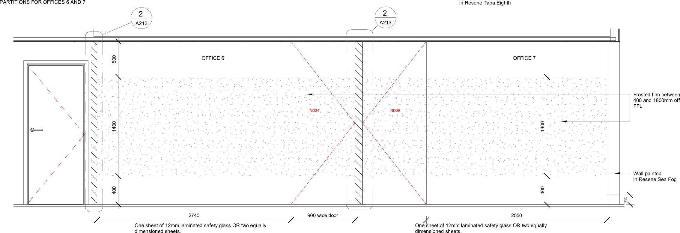 |
|
!R GRWP |
CLIENT PROJECT ADDRESS STATUS DRAWING Sheet No. A208 This design and drawing is the copyright of IR Group Ltd and is NAENAE COLLEGE INTERIOR UPGRADE OF 910 HIGH STREET TENDER/CONSENT ALUMINIUM INTERIOR Scale 1 : 25 @ A3 not to be reproduced without |
|
PLAN DESIGN DELIVER |
ADMINISTRATION BLOCK AVALON DRAWINGS PARTITIONS written permission. |
|
027 6222 138 716 Main Road North, Upper Hutt |
Date AUGUST 2022 LOWER HUTT 5011 Do not scale from drawings. Drawn By JANINE FENELON |
1/A209 ELEVATION FROM WAIT AREA SHOWING INTERIOR PARTITIONS INTO OFFICES 2 AND 3
|
Clear timber trim | |
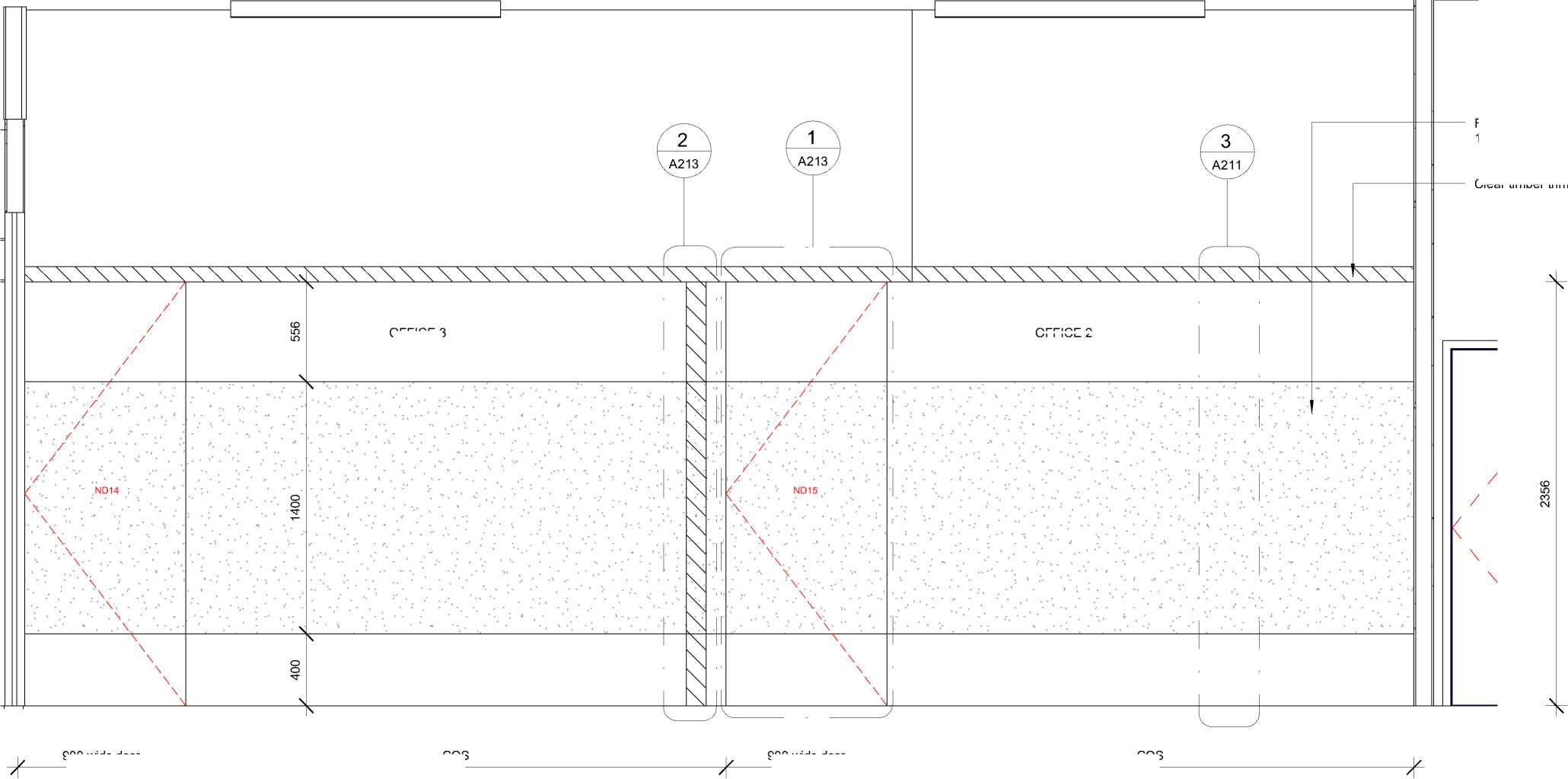
OFFICE 2 ND14 ND15 |
Frosted film between 400 and 1800mm off FFL |
|
900 wide door COS 900 wide door COS | |
OFFICE 3
One sheet of 12mm laminated safety glass OR two equally dimensioned sheets.
One sheet of 12mm laminated safety glass OR two equally dimensioned sheets.
| ||||||||||||||||
|
716 Main Road North, Upper Hutt |
|
STATUS |
DRAWING |
Sheet No. |
A209 |
This design and drawing is the copyright of IR Group Ltd and is |
|
TENDER/CONSENT |
ALUMINIUM INTERIOR |
Scale |
1 : 25 @ A3 |
not to be reproduced without |
|
DRAWINGS |
PARTITIONS |
Date |
AUGUST 2022 |
written permission. Do not scale from drawings. |
Drawn By JANINE FENELON

|
Door into Office 5 Clear timber trim 90x10mm |
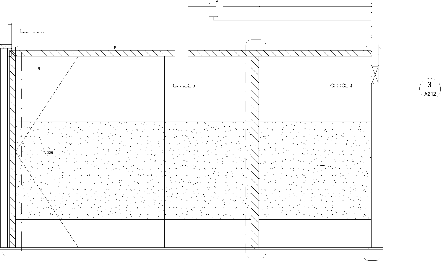
OFFICE 5 OFFICE 4 ND25 |
|
Frosted film from 400 to 1800 above FFL 900 1236 1236 1613 |

2
HALLWAY


3373
|
IR GR^UP |
CLIENT PROJECT ADDRESS STATUS DRAWING Sheet No. A210 This design and drawing is the copyright of IR Group Ltd and is NAENAE COLLEGE INTERIOR UPGRADE OF 910 HIGH STREET TENDER/CONSENT ALUMINIUM INTERIOR Scale 1 : 25 @ A3 not to be reproduced without |
|
PLAN DESIGN DELIVER |
ADMINISTRATION BLOCK AVALON DRAWINGS PARTITIONS written permission. |
|
027 6222 138 716 Main Road North, Upper Hutt |
Date AUGUST 2022 LOWER HUTT 5011 Do not scale from drawings. Drawn By JANINE FENELON |
Ceiling Level
Glazing Wedge
|
3/A211 FULL HEIGHT GLAZING SECTION (E64-03) Fixing Stake 01, 02, AE010 64mm Headtrack | 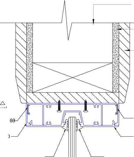 |
Framing Interior lining Fixing Stake 01, 02, 03 AE016 64mm Pocket Clip-In Filler Clear timber trim 90x10mm |
Glazing Wedge
2/A211 FULL HEIGHT GLAZING SECTION (E64-03)
12mm laminated safety glass
AE010
64mm Pocket Headtrack
IR GR^UP
PLAN DESIGN DELIVER
|
Glazing Wedge Glazing Wedge Setting Block Fixing Stake 01, 02, 03 Fixing Stake 01, 02, 03 Floor Level AE020 64mm Glazing Bead AE019 64mm Glazing Track |
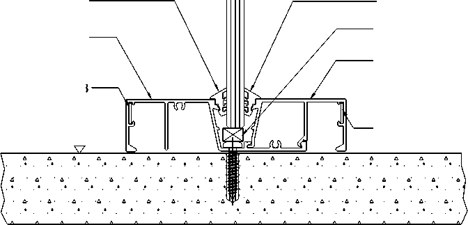 |
CLIENT
PROJECT
ADDRESS
STATUS
NAENAE COLLEGE
INTERIOR UPGRADE OF
ADMINISTRATION BLOCK
910 HIGH STREET
AVALON
LOWER HUTT 5011
TENDER/CONSENT DRAWINGS
|
Fixing Stake 01, 02, Glazing Wedge Glazing Wedge Fixing Stake 01, 02, 0 AE010 64mm Headtrack | 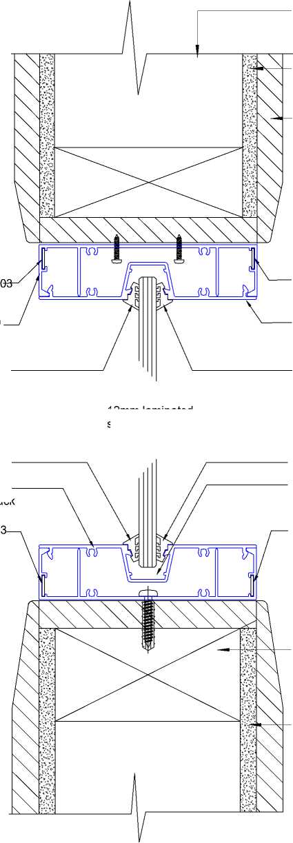 |
Framing Interior lining Fixing Stake 01, 02, 03 Glazing Wedge Glazing Wedge Setting Block Fixing Stake 01, 02, 03 10mm GIB lining 12mm laminated safety glass Top plate 90x45 SG8 for fixing Clear timber trim 90x10mm AE016 64mm Pocket Clip-In Filler |
DRAWING
Sheet No.
A211
ALUMINIUM INTERIOR PARTITIONS - DETAILS
Scale
Date
Drawn By
1 : 50 @ A3
AUGUST 2022
JANINE FENELON
This design and drawing is the copyright of IR Group Ltd and is not to be reproduced without written permission.
Do not scale from drawings.
|
2/A212 ECLIPSE 64 TERMINATION DETAIL WITH TIMBER TRIM (E64-12) |
3/A212 ECLIPSE 64 TERMINATION DETAIL INTO CONCRETE WALL (E64-12) |
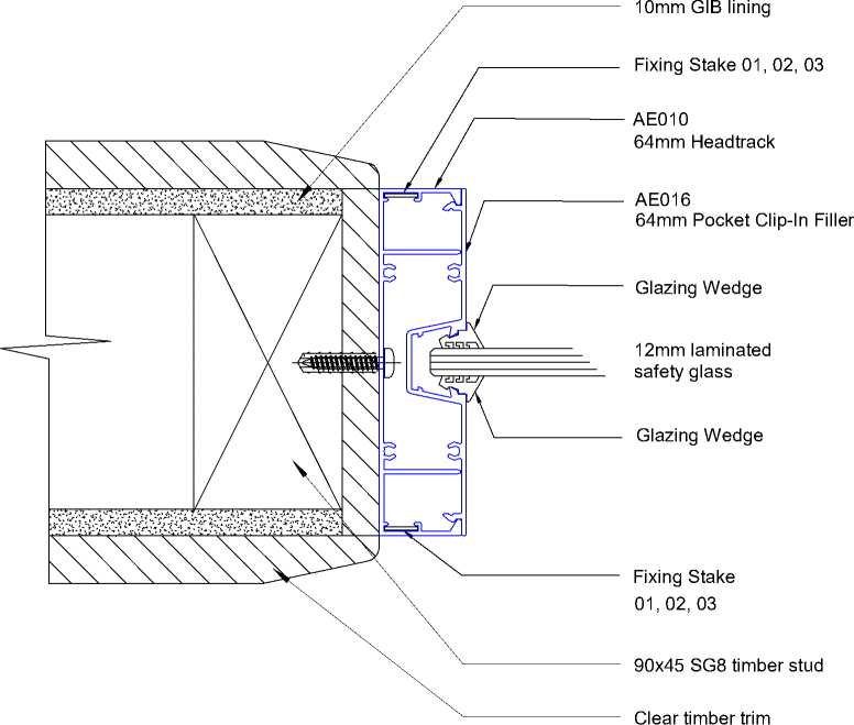 |
|
90 x 10 |
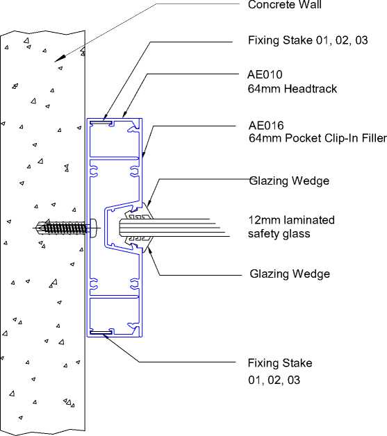
1/A212 ECLIPSE 64 DOOR PLAN (E64-09)
|
12mm laminated safety glass | 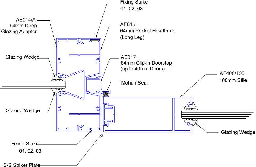 |
12mm laminated safety glass |
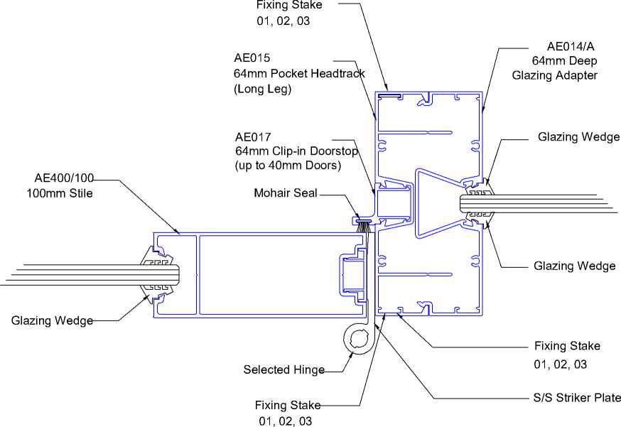 |
12mm laminated safety glass |
|
!R GRWP |
CLIENT |
PROJECT |
ADDRESS |
STATUS |
DRAWING |
Sheet No. |
A212 |
This design and drawing is the copyright of IR Group Ltd and is |
|
NAENAE COLLEGE |
INTERIOR UPGRADE OF |
910 HIGH STREET |
TENDER/CONSENT |
ALUMINIUM INTERIOR |
Scale |
1 : 50 @ A3 |
not to be reproduced without | |
|
PLAN DESIGN DELIVER |
ADMINISTRATION BLOCK |
AVALON |
DRAWINGS |
PARTITIONS - DETAILS |
Date |
written permission. | ||
|
janine@irgroup.co.nz 027 6222 138 |
LOWER HUTT 5011 |
AUGUST 2022 |
Do not scale from drawings. | |||||
|
716 Main Road North, Upper Hutt |
Drawn By |
JANINE FENELON |
|
!R GROUP |
CLIENT |
PROJECT |
ADDRESS |
STATUS |
DRAWING |
Sheet No. |
A213 |
This design and drawing is the copyright of IR Group Ltd and is |
|
NAENAE COLLEGE |
INTERIOR UPGRADE OF |
910 HIGH STREET |
TENDER/CONSENT |
ALUMINIUM INTERIOR |
Scale |
As indicated @ A3 |
not to be reproduced without | |
|
PLAN DESIGN DELIVER |
ADMINISTRATION BLOCK |
AVALON |
DRAWINGS |
PARTITIONS - DETAILS |
Date |
written permission. | ||
|
janine@irgroup.co.nz 027 6222 138 |
LOWER HUTT 5011 |
AUGUST 2022 |
Do not scale from drawings. | |||||
|
716 Main Road North, Upper Hutt |
Drawn By |
JANINE FENELON |
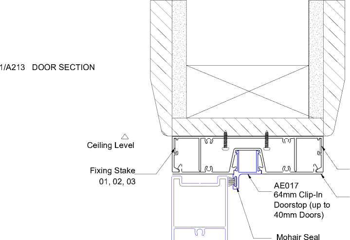 |
AE010 64mm Headtrack AE016 64mm Pocket Clip-In Filler |
2/A213 DOOR PLAN SHOWING INTERSECTION WITH TIMBER FRAMED WALL
10mm GIB lining
Fixing Stake 01, 02, 03
AE010
64mm Headtrack
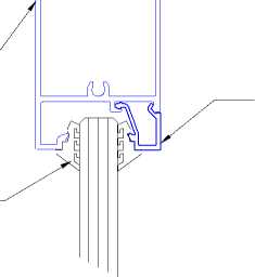
AE016
64mm Pocket Clip-In Filler
Glazing Wedge
Selected Glazing To Comply With Glazing Standards
Glazing Wedge
|
Selected Glazing to comply with glazing standards Glazing Wedge Setting Block Door Seal Insert Floor Level AE402/100 80mm Bottom Rail AE403 Door Glazing Bead RP88I Raven Seal |
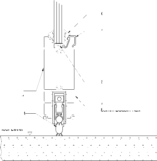 |
Fixing Stake
01, 02, 03
90x45 SG8 timber stud
Clear timber trim
90 x 10
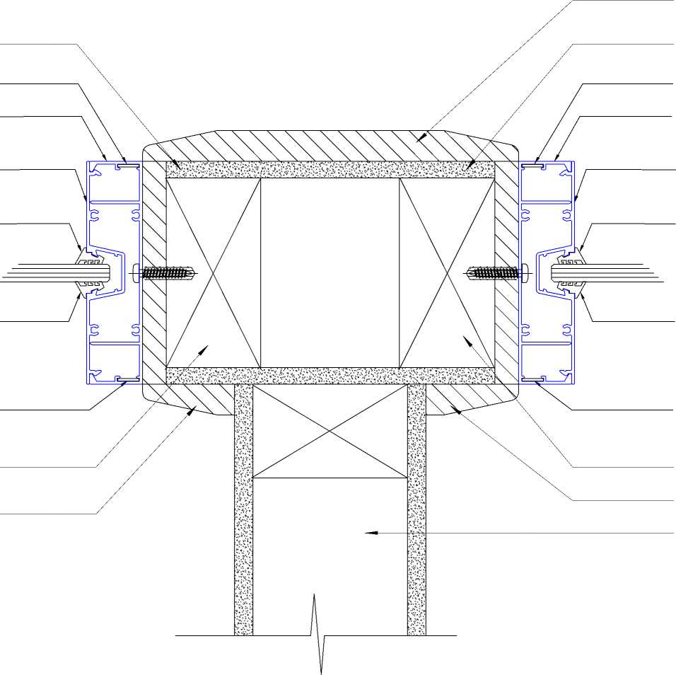
Clear timber trim
90 x 10
10mm GIB lining
Fixing Stake 01, 02, 03
AE010
64mm Headtrack
AE016
64mm Pocket Clip-In Filler
Glazing Wedge
Selected Glazing To Comply With Glazing Standards
Glazing Wedge
Fixing Stake
01, 02, 03
90x45 SG8 timber stud
Clear timber trim
90 x 10
Timber framed wall with 10mm GIB lining
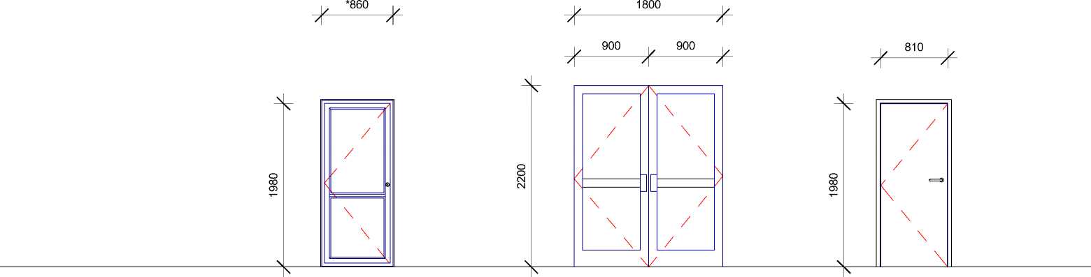
DOOR SCHEDULE
ND01, ND02 and ND03
Doors specified by Resolve Architects
ND04, ND05, ND06, ND10,
ND11, ND12, ND13 and ND16
100mm commercial powdercoated aluminium framed door with glass
panels and mid-vision rail
Colour of aluminium to be selected
Single glazing Grade A safety glass
Legge 500 series Plate with Ergo 62
lever (512 plain plate) - satin chrome
Assa Abloy 250A door stop, or comparable for each interior door
ND07 and ND23
ND08, ND17 and ND18
Solid hardwood timber French double doors with glass panels and mid-vision rails.
Single glazing Grade A safety glass
Doors to swing both ways
Drake and Wrigley 1091 Push Plates (satin chrome) on both faces of each door
40mm interior hollow core flush faced door. Paint quality finish. Colours for doors ND17 and ND18 to be selected
ND08 to be lined with Autex Composition on Admin office face. Colour to be selected
SA85x18 architrave clear coated with Resene Aquaclear
Legge 500 series plate with Ergo 62 lever (512 plain plate). Satin chrome
Assa Abloy A250 door stop, or comparable for each interior door
|
MARK |
LOCATION |
HEIGHT |
WIDTH |
|
ND01 |
Reception |
2200 |
2000 |
|
ND02 |
Wind Lobby |
2200 |
3000 |
|
ND03 |
Student Entrance |
2200 |
2000 |
|
ND04 |
Lobby |
2000 |
860 |
|
ND05 |
Hallway |
2000 |
860 |
|
ND06 |
Admin Office |
2000 |
860 |
|
ND07 |
Hallway |
2200 |
900 |
|
ND08 |
Store 2 |
1980 |
810 |
|
ND10 |
Sick Bay |
2000 |
860 |
|
ND11 |
Meeting Room |
2000 |
860 |
|
ND12 |
Office 4 |
2000 |
860 |
|
ND13 |
Office 4 |
2000 |
860 |
|
ND16 |
Office 1 |
2000 |
860 |
|
ND17 |
Store 1 |
1980 |
810 |
|
ND18 |
Toilet Lobby |
1980 |
810 |
|
ND19 |
WC1 |
1980 |
760 |
|
ND20 |
WC2 |
1980 |
760 |
|
ND21 |
WC3 |
1980 |
760 |
|
ND22 |
Office 1 |
1980 |
1800 |
|
ND23 |
Hallway |
2200 |
900 |
 |
|
ND19, ND20 and ND21 ND22 ND09, ND14, ND15, ND24 and ND25 |
40mm interior solid core door with 25mm undercut, clashed 4 edges and fitted with 4 rising butt hinges.
40mm solid core flush faced. Paint quality. Colour(s) to be selected
Holyoake DG52BFL Door grille (300Hx300W)
SA85x18 architrave clear coated with Resene Aquaclear
100mm commercial powdercoated aluminium framed double sliding door with mid-vision rail
Colour of aluminium TBC
Single glazing Grade A safety glass
Schalge Silvi BTB Pull Handle
OA 316L SS on both sides of door.
Handles positioned on aluminium frame
Doors will constitute part of the aluminium framed glass partition suite.
DOOR NOTES
-
• Contractor to check and confirm all dimensions of
doors and windows on site before manufacture
-
• All aluminium joinery to comply with NZS4211 and to
be powder coated commercial suite
-
• All glazing to comply with NZS4223.3:2016
-
• Clear single glazing for all interior doors, windows
and glass partitions
Safety Glass Installation
Use in doors, interior partitions, sidelight panels, low level windows and all other locations to comply with NZS4223, part 3 as modified by NZBC F2/AS1 1.0 Glazing
Hinges
Hang interior doors on 100mm LP bronzed steel butts, 3 butts per door
For hardwood double doors, 4 butts per door
Drake and Wrigley 1466 Offset pull handle on plate on inside face
Lockwood 801 Indicator Bolt
| ||||||||||||
|
027 6222 138 716 Main Road North, Upper Hutt |
Sheet No. A214
Scale 1 : 50 @ A3
Date AUGUST 2022
Drawn By JANINE FENELON
This design and drawing is the copyright of IR Group Ltd and is not to be reproduced without written permission.
Do not scale from drawings.
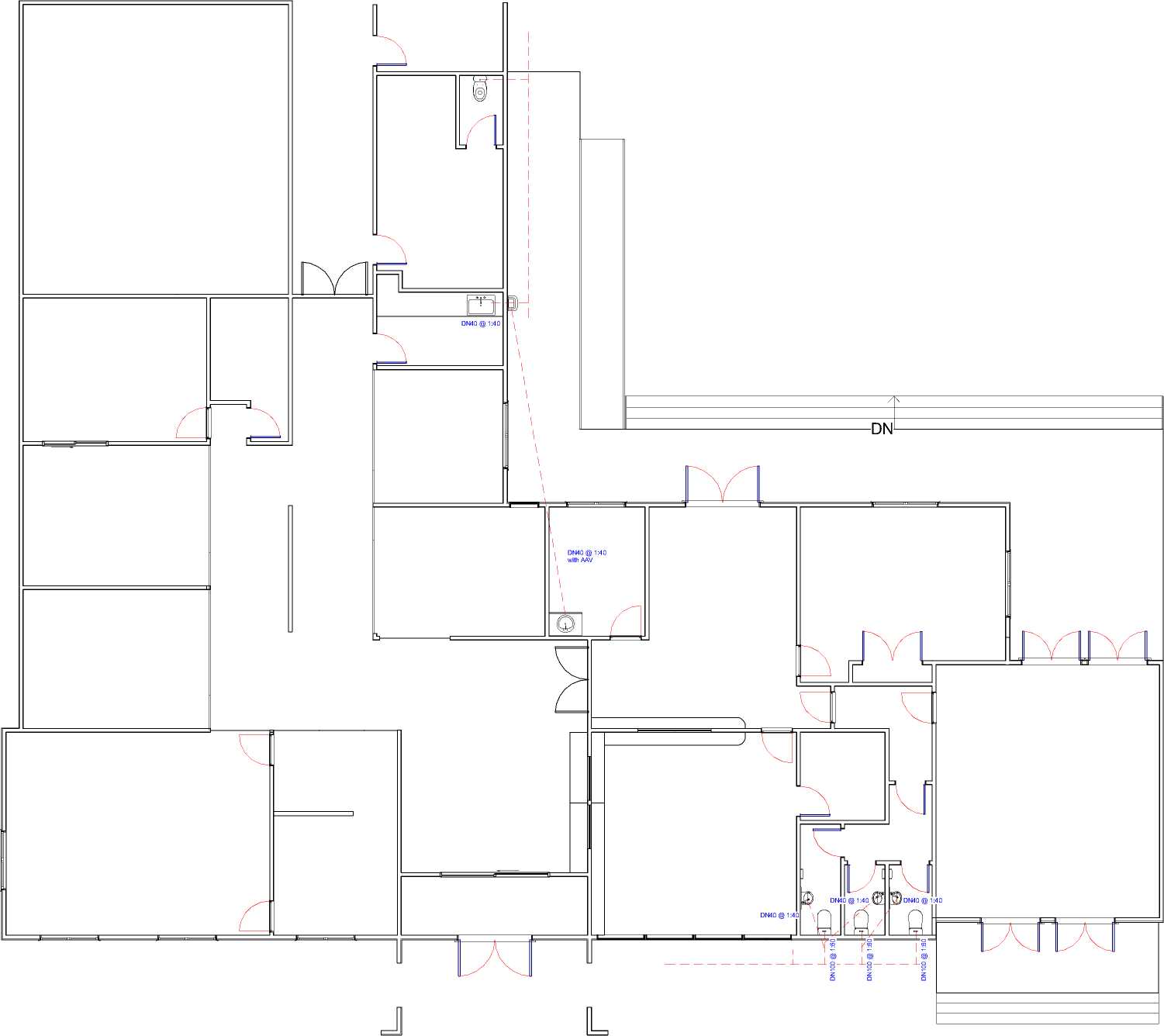
PLUMBING NOTES
Contractor to ensure all work complies with the NZBC and relevant standards, along with local territorial authority bylaws prior to work commencing.
All Foul Water plumbing work to comply with AS/NZS3500.2:2015 and all Storm Water plumbing work to comply with E1/AS1 and AS/NZS3500.3:2015
Water Supply
Water supply pipe materials to comply with G12/AS1 Table 1:
Hot and cold: Copper, stainless steel or polybutylene
Cold only: uPVC or polyethylene
All hot and cold water pipework through slab shall be in DN65 uPVC conduit.
All hot water piping shall be thermally insulated to comply with H1/AS1 Clause 5.0 hot water systems.
All water supply pipe sizes installed to comply with G12/AS1 Table 4:
Mains connection to building: 20mm dia, polyethylene
Sink and WHB basin: 15mm dia. polybutylene
Pipes based on a maximum pipe length of 20m
Water pipes to achieve the flow rates given in G12 Table 3 or to be sized using the dimensions in G12 Table 4.
Ensure hot water temperature at any sanitary fixture used for personal hygiene does not exceed 450.
Fixture Trap and Waste Sizes
Fixture traps for hand basins and sinks to be DN40 trap, DN65 drain pipe
Fixture traps from WC to be DN 100 trap and DN100 drain.
|
IR GR^UP |
CLIENT PROJECT ADDRESS STATUS DRAWING Sheet No. A300 This design and drawing is the copyright of IR Group Ltd and is NAENAE COLLEGE INTERIOR UPGRADE OF 910 HIGH STREET TENDER/CONSENT PLUMBING AND Scale 1 : 125 @ A3 not to be reproduced without |
|
PLAN DESIGN DELIVER |
ADMINISTRATION BLOCK AVALON DRAWINGS DRAINAGE written permission. |
|
027 6222 138 716 Main Road North, Upper Hutt |
Date AUGUST 2022 LOWER HUTT 5011 Do not scale from drawings. Drawn By JANINE FENELON |
ELECTRICAL NOTES
All electrical works to comply with NZBC F7/AS1, AS/NZS 3000:2007, AS/NZS 3008.1.2:2010 and AS/NZS 5000.2:2006.
Run any new wiring in wall cavities/ceilings before new linings are fitted.
ELECTRICAL AND LIGHTING LEGEND
|
Recessed downlights are to be CA135, CA180, IC or IC-F to comply with AS/NZS 60598.2.2 Amendment A. Location of exterior lighting to be specified by other All power points 300mm off FFL. To comply with G9/AS1 2.0 all new light switches are to be horizontally aligned with door handles and 1000mm off FFL. Toggles or button control of light switches shall project clear of the switch plate. All habitable internal spaces to have a minimum illuminance of 20lux or a minimal total wattage required per m2 of floor area as shown in G8/AS1 Table 1. Lighting Supply and fit new light fittings, associated light switches and wiring to suit at locations shown on drawings. Power Outlets Allow for each new wall to have at least one new double power outlet Mechanical Ventilation Three WC's to be mechanically ventilated with a combined Solatube/ventilation system, specified by others |
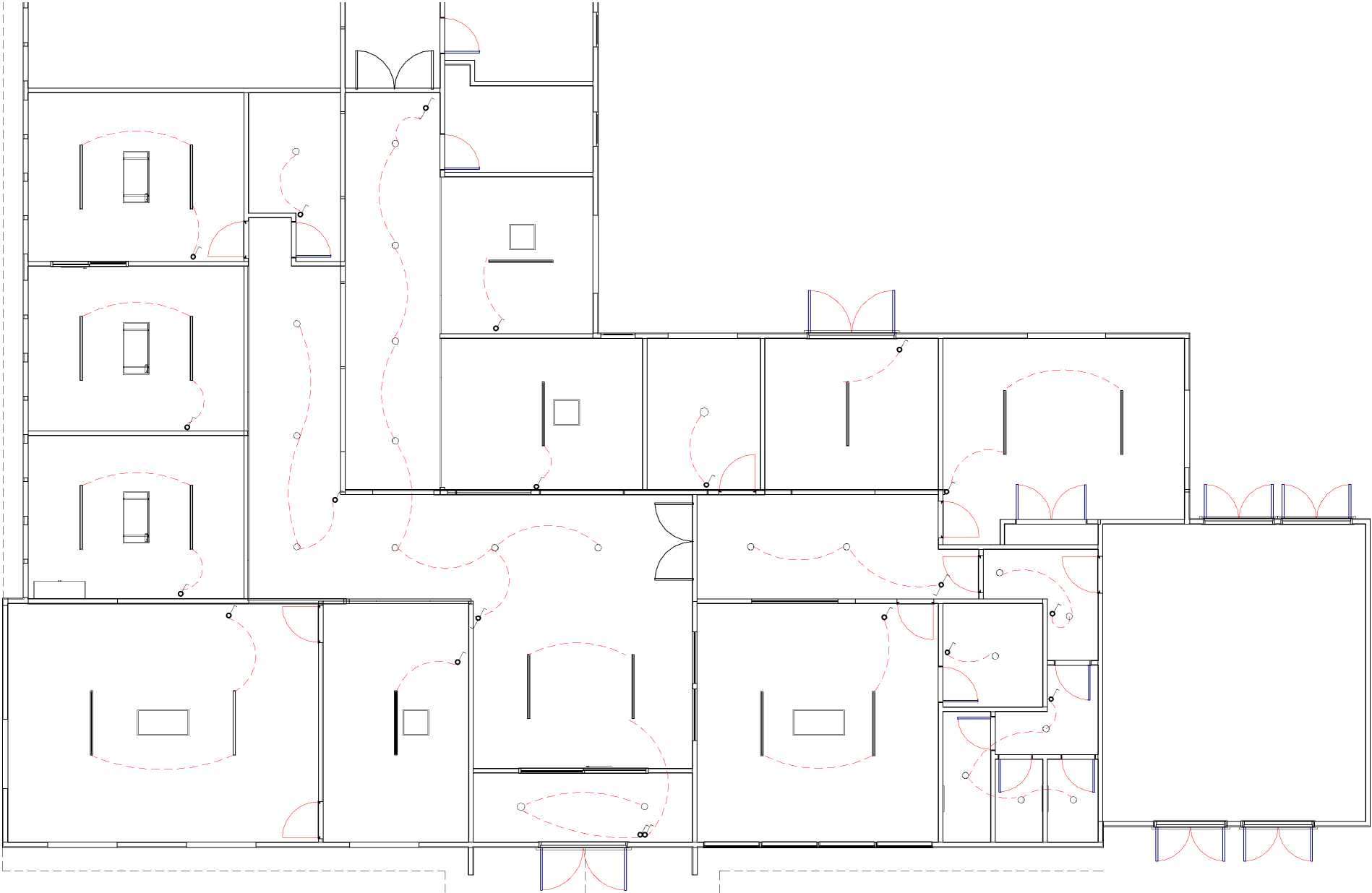 |
LED ceiling batten
LED recessed ceiling light
Light switch
Two way light switch
Single power outlet
Double power outlet
Electrical circuit
EnergoCassette ENC300
EnergoCassette ENC600

|
!R GRWP |
CLIENT |
PROJECT |
ADDRESS |
STATUS |
DRAWING |
Sheet No. |
A301 |
This design and drawing is the copyright of IR Group Ltd and is |
|
NAENAE COLLEGE |
INTERIOR UPGRADE OF |
910 HIGH STREET |
TENDER/CONSENT |
ELECTRICAL AND |
Scale |
As indicated @ A3 |
not to be reproduced without | |
|
PLAN DESIGN DELIVER |
ADMINISTRATION BLOCK |
AVALON |
DRAWINGS |
LIGHTING |
Date |
written permission. | ||
|
janine@irgroup.co.nz 027 6222 138 |
LOWER HUTT 5011 |
AUGUST 2022 |
Do not scale from drawings. | |||||
|
716 Main Road North, Upper Hutt |
Drawn By |
JANINE FENELON |
2/A401 DETAIL SHOWING ADDITION OF NEW LINTELS ABOVE ALUMINIUM PARTITIONS AND CHANGES TO EXISTING JOISTS IN HALLWAY
1:10
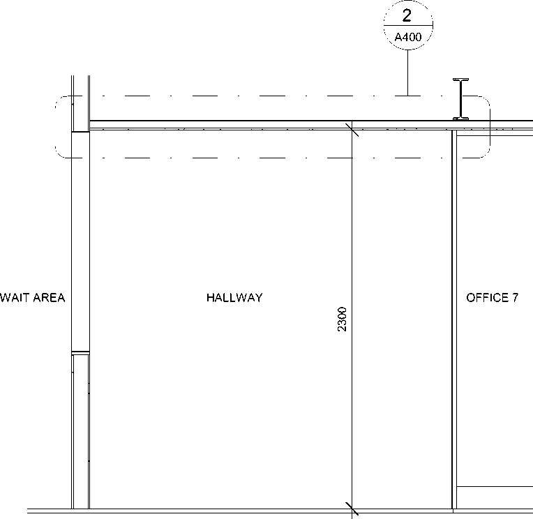
Eclipse 64mm aluminium suite

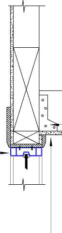
Existing ceiling cut back to allow for existing joists to be hung off new lintel. Size to be confirmed by engineer.
Allow for ceiling lining to be replaced with 13mm GIB and painted in Resene Ceiling White
13mm GIB ceiling lining New lintel specified by engineer. Phonic ceiling tiles Max. height 150mm direct fixed to existing
ceiling lining
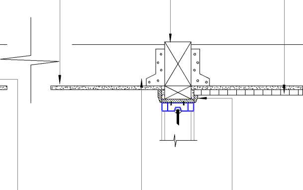 |
|
Clear timber trim |
Mitek JH47x90 joist hanger
Existing joist cut to allow for new lintel to be inserted
|
|
|
4200 1265 2000 935 669 1200 1200 1819010 ELEVATION B V BENCH @ 900mm 18 -718 | |
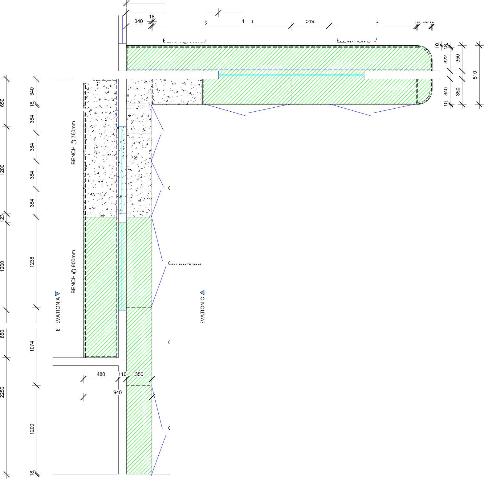
© it.. |
OPEN SHELVES CUPBOARDS CUPBOARDS |
|
CUPBOARDS OPEN SHELVES CUPBOARDS ELEVATION D A INTERIOR JOINERY Benchtop Cabinetry OPEN SHELVES Decorative Panels • Hardware • • Frameless sliding windows CUPBOARDS LU —I LU FLOOR PLAN OF RECEPTION COUNTERS IN MAIN RECEPTION AREA AND IN STUDENT RECEPTION AREA • • • • • • • • • | |
CLIENT
NAENAE COLLEGE
CUPBOARDS
LU
—I LU
PROJECT
ADDRESS
STATUS
DRAWING
Dimensions to be checked and confirmed on site by contractor before manufacture of any interior joinery
Given that the cabinetry and counters are wall hung, additional dwangs need to be incorporated in the wall framing
30mm benchtop in same material for both benchtop heights
Material and colour to be selected
Benchtop on reception and student reception side of the design to be supported by a timber cleat (100x25mm)
All carcasses to be 18mm double sided white MUF
Doors, open shelves, end panels and base panels to be LPL (18mm) in selected colour with 2mm edge tape in colour to match.
One adjustable shelf in each cupboard
Open shelves at fixed heights
Decorative panels on Elevation A and Elevation C of the reception counter to be selected
All hardware to be Blum, Hettich or Hafele or comparable. This includes hinges, handles and all accessories
Elite Amelia Cross Bar 192mm BN (12 handles) r
Hafele EKU CLIPO 16 GPPK track system for sliding frameless glass windows 6mm glass to be supplied by glazier
Sheet No.
A401
INTERIOR UPGRADE OF
ADMINISTRATION BLOCK
910 HIGH STREET
AVALON
LOWER HUTT 5011
TENDER/CONSENT DRAWINGS
INTERIOR JOINERY -
RECEPTION COUNTER
Scale
Date
Drawn By
1 : 25 @ A3
AUGUST 2022
JANINE FENELON
This design and drawing is the copyright of IR Group Ltd and is not to be reproduced without written permission.
Do not scale from drawings.
ELEVATION A
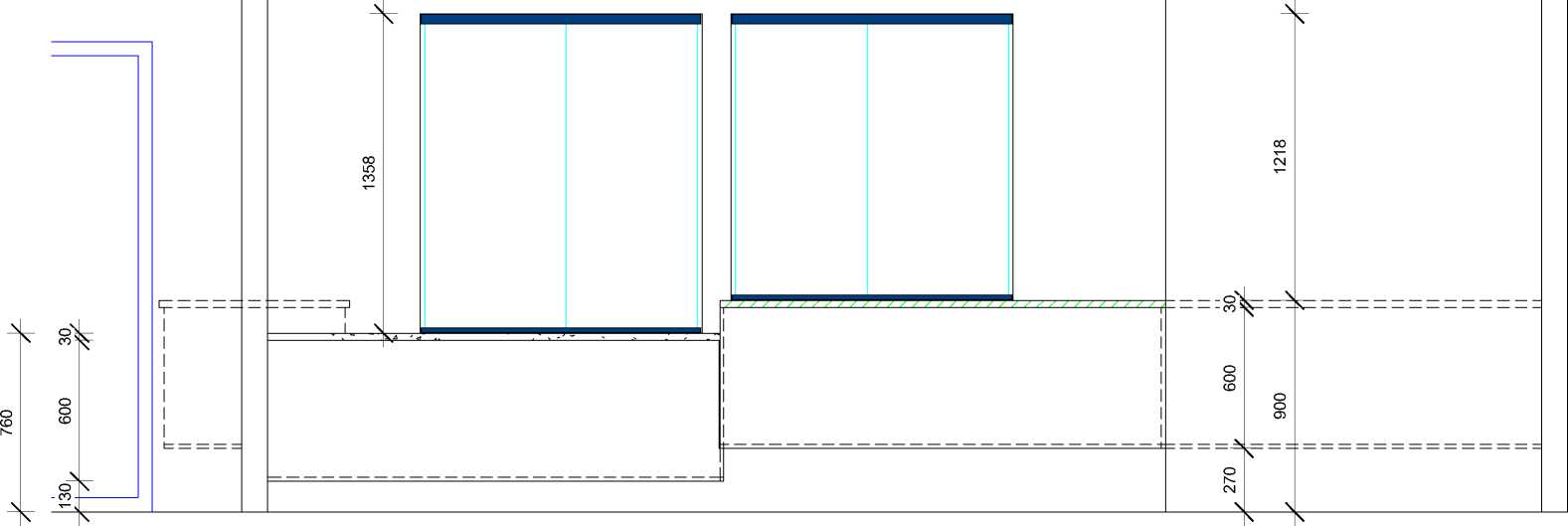
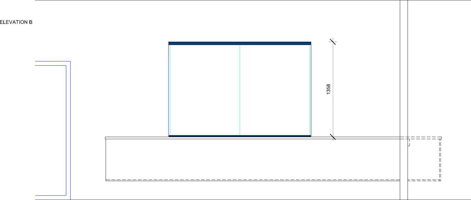
INTERIOR JOINERY
Dimensions to be checked and confirmed on site by contractor before manufacture of any interior joinery
Given that the cabinetry and counters are wall hung, additional dwangs need to be incorporated in the wall framing
Benchtop
•
•
•
30mm benchtop in same material for both benchtop heights
Material and colour to be selected
Benchtop on reception and student reception side of the design to be supported by a timber cleat (100x25mm)
Cabinetry
•
•
•
•
All carcasses to be 18mm double sided white MUF
Doors, open shelves, end panels and base panels to be LPL (18mm) in selected colour with 2mm edge tape in colour to match.
One adjustable shelf in each cupboard
Open shelves at fixed heights
Decorative Panels
•
Decorative panels on Elevation A and Elevation C of the reception counter to be selected
Hardware
•
•
All hardware to be Blum, Hettich or Hafele or comparable. This includes hinges, handles and all accessories
Allow PC sum of $15/handle
Frameless sliding windows
•
•
Hafele EKU CLIPO 16 GPPK track system for sliding frameless glass windows 6mm glass to be supplied by glazier
IR GR^UP
CLIENT
PROJECT
ADDRESS
STATUS
DRAWING
Sheet No.
A402
PLAN DESIGN DELIVER
NAENAE COLLEGE
INTERIOR UPGRADE OF
ADMINISTRATION BLOCK
910 HIGH STREET
AVALON
LOWER HUTT 5011
TENDER/CONSENT DRAWINGS
INTERIOR JOINERY -
RECEPTION COUNTER
Scale
Date
Drawn By
1 : 25 @ A3
AUGUST 2022
JANINE FENELON
This design and drawing is the copyright of IR Group Ltd and is not to be reproduced without written permission.
Do not scale from drawings.
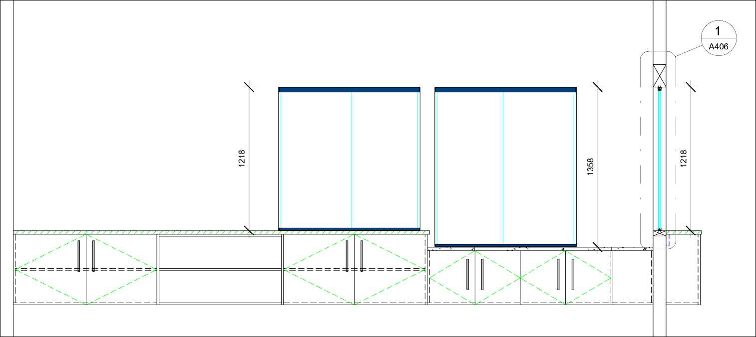
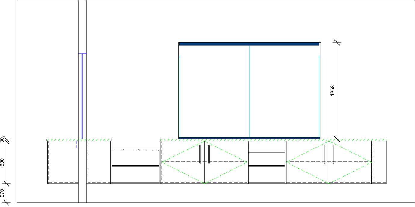
ELEVATION D
INTERIOR JOINERY
Dimensions to be checked and confirmed on site by contractor before manufacture of any interior joinery
Given that the cabinetry and counters are wall hung, additional dwangs need to be incorporated in the wall framing
Benchtop
-
• 30mm benchtop in same material for both benchtop heights
-
• Material and colour to be selected
-
• Benchtop on reception and student reception side of the design to be supported by
a timber cleat (100x25mm)
Cabinetry
-
• All carcasses to be 18mm double sided white MUF
-
• Doors, open shelves, end panels and base panels to be LPL (18mm) in selected
colour with 2mm edge tape in colour to match.
-
• One adjustable shelf in each cupboard
-
• Open shelves at fixed heights
Decorative Panels
-
• Decorative panels on Elevation A and Elevation C of the reception counter to be
selected
Hardware
-
• All hardware to be Blum, Hettich or Hafele or comparable. This includes hinges,
handles and all accessories
-
• Elite Amelia Cross Bar 192mm BN (12 handles)
Frameless sliding windows
-
• Hafele EKU CLIPO 16 GPPK track system for sliding frameless glass windows
-
• 6mm glass to be supplied by glazier
|
CLIENT |
PROJECT |
ADDRESS |
STATUS |
DRAWING |
Sheet No. |
A403 |
This design and drawing is the copyright of IR Group Ltd and is |
|
NAENAE COLLEGE |
INTERIOR UPGRADE OF ADMINISTRATION BLOCK |
910 HIGH STREET AVALON LOWER HUTT 5011 |
TENDER/CONSENT DRAWINGS |
INTERIOR JOINERY - RECEPTION COUNTER |
Scale Date Drawn By |
1 : 25 @ A3 AUGUST 2022 JANINE FENELON |
not to be reproduced without written permission. Do not scale from drawings. |
KITCHEN JOINERY ELEVATION
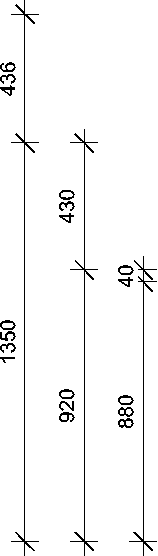
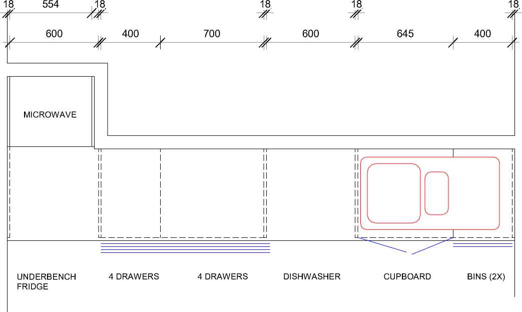
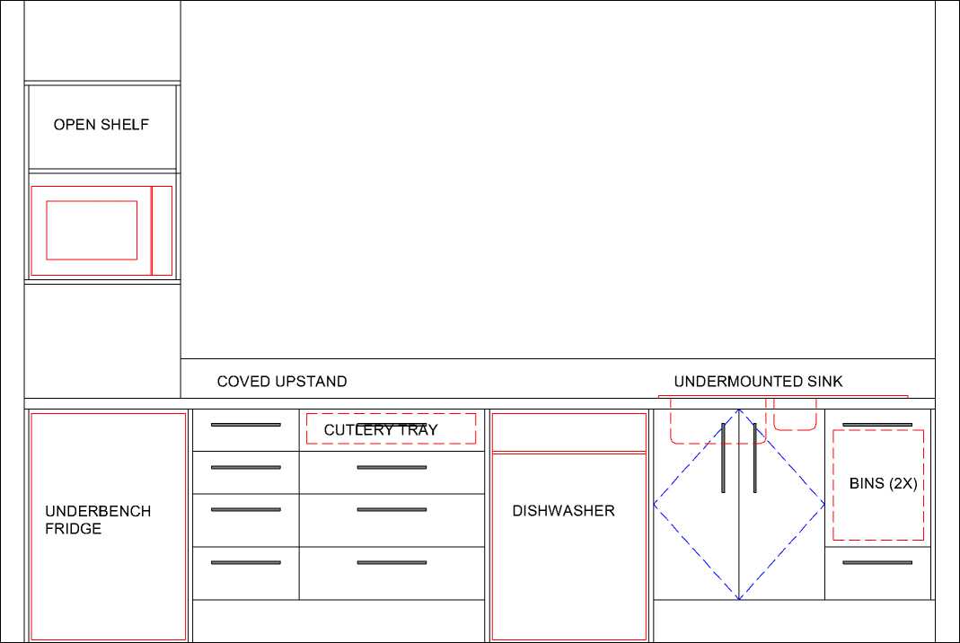


KITCHEN AND SICK BAY JOINERY
Dimensions to be checked and confirmed on site by contractor before manufacture of any interior joinery
Benchtop
-
• 40mm HPL with arris edge and 150mm coved upstand
-
• Colour to be selected
Cabinetry
-
• All carcasses to be 18mm double sided white MUF
-
• Drawer fronts, doors, open shelves, end panels and back
panels to be LPL (18mm) in selected colour with 2mm edge tape
-
• One adjustable shelf in each cupboard
-
• Open shelves and overhead shelves to be adjustable
in colour to match.
Hardware
-
• All hardware to be Blum, Hettich, Hafele or comparable.
This includes hinges, handles and all accessories e.g. cutlery tray
-
• All drawers to be self-close
-
• Elite Amelia Cross Bar 192mm BN handles (14 handles for kitchen and sick bay)
Kitchen Sink
-
• IKON Centurio 1.5 IK723143l double sink with drainer, undermounted in benchtop
Sick Bay Sink
-
• Oliveri LR510 NZ single round bowl, undermounted in benchtop
Tap
-
• Methven Glide sink mixer for both the kitchen and sick bay
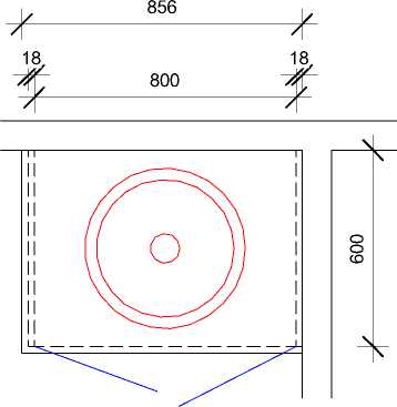
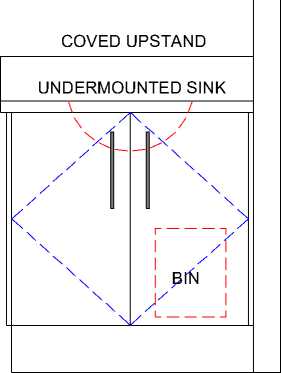
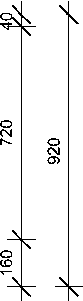
SICK BAY JOINERY PLAN
SICK BAY JOINERY ELEVATION
|
CLIENT |
PROJECT |
ADDRESS |
STATUS |
DRAWING |
Sheet No. |
A404 |
This design and drawing is the copyright of IR Group Ltd and is |
|
NAENAE COLLEGE |
INTERIOR UPGRADE OF ADMINISTRATION BLOCK |
910 HIGH STREET AVALON LOWER HUTT 5011 |
TENDER/CONSENT DRAWINGS |
INTERIOR JOINERY - KITCHEN AND SICK BAY |
Scale Date Drawn By |
1 : 20 @ A3 AUGUST 2022 JANINE FENELON |
not to be reproduced without written permission. Do not scale from drawings. |
HAFELE EKU CLIPO 16 GPPK FOR SLIDING FRAMELESS WINDOWS IN RECEPTION AND ADMIN AREA
NOTE
EKU CLIPO 16 GPK/GPPK
The EKU CLIPO Model GPPK will be used for the frameless glass windows in the reception/admin area
Soft closing mechanism for all sliding windows and locks (3x) for each window
2 x 6mm glass for each window not supplied as part of the Hafele system. To be supllied by glazier
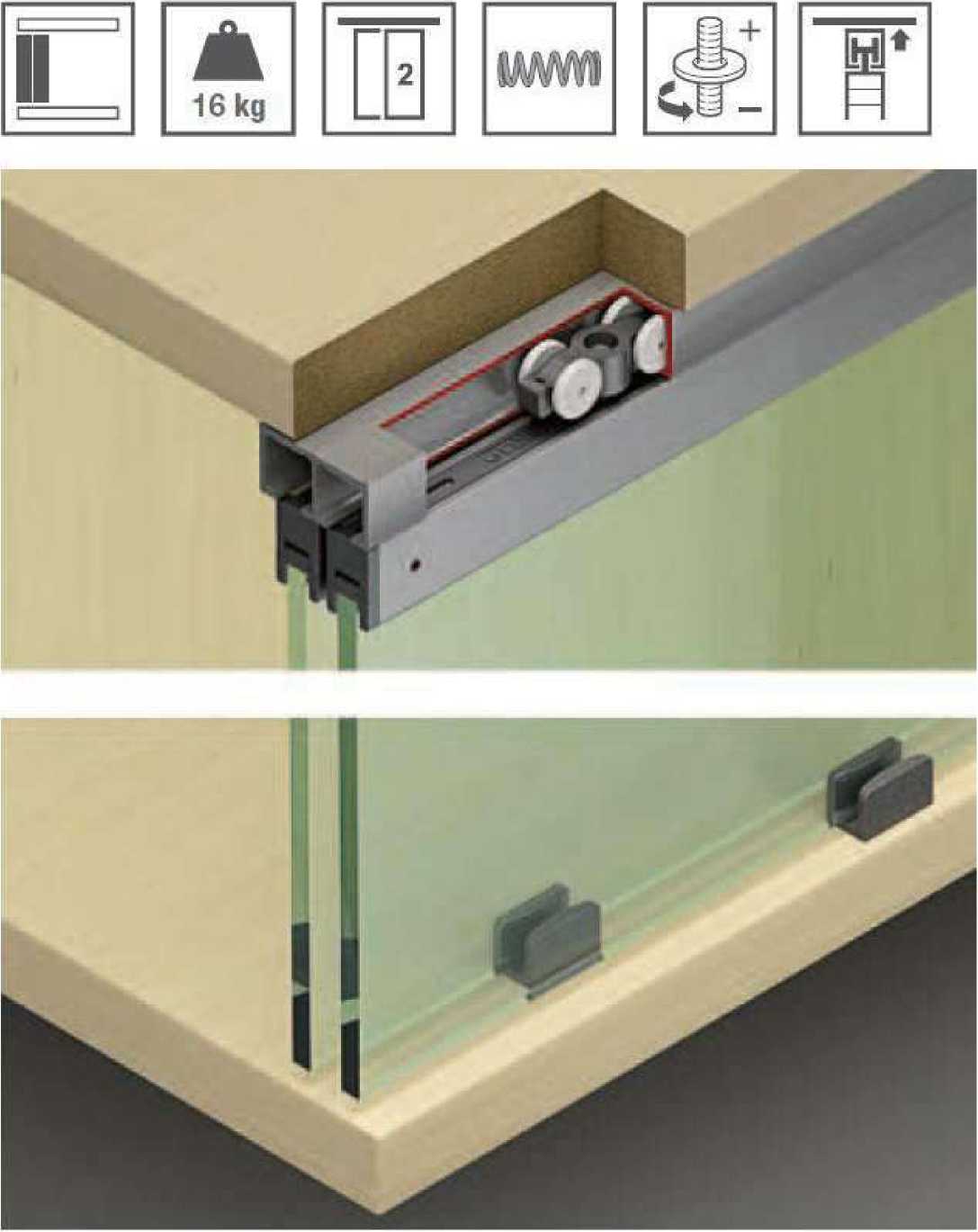 |
|
!R GR^UP PLAN DESIGN DELIVER 027 6222 138 716 Main Road North, Upper Hutt |
-
> Version: Model GPK with top glass retaining
profile and visible bottom guide with zero clearance.
Model GPPK with top and bottom glass retaining profile and concealed bottom guide with zero clearance, with soft closing mechanism (optional)
-
> Door height (mm): <1400
-
> Door width (mm): <1000
-
> Glass thickness (mm): 6
-
> Door stopper: Top door stopper
-
> Material: Plastic
-
> Running gear: Top running, 2 rollers
-
> Running gear guided by: Friction bearing mounted roller: Plastic,
-
> Adjustment facility (mm): +2/-1 on running gear
-
> Installation: Running gear without tools
(quick fixing system), guide for screw fixing without glass preparation
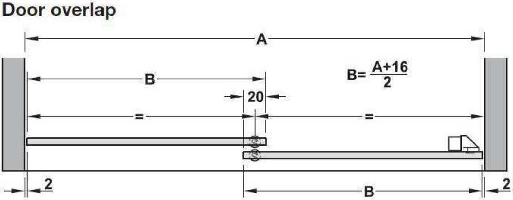
A = Internal cabinet width H = Internal cabinet height B = Door width
| ||||||||
|
LOWER HUTT 5011 |
|
DRAWING |
Sheet No. |
A405 |
This design and drawing is the copyright of IR Group Ltd and is |
|
FRAMELESS SLIDING |
Scale |
@ A3 |
not to be reproduced without |
|
WINDOWS |
Date Drawn By |
AUGUST 2022 JANINE FENELON |
written permission. Do not scale from drawings. |
1/A406 HEAD AND COUNTER TRACK DETAILS FOR FRAMELESS SLIDING GLASS WINDOWS
NOT TO SCALE
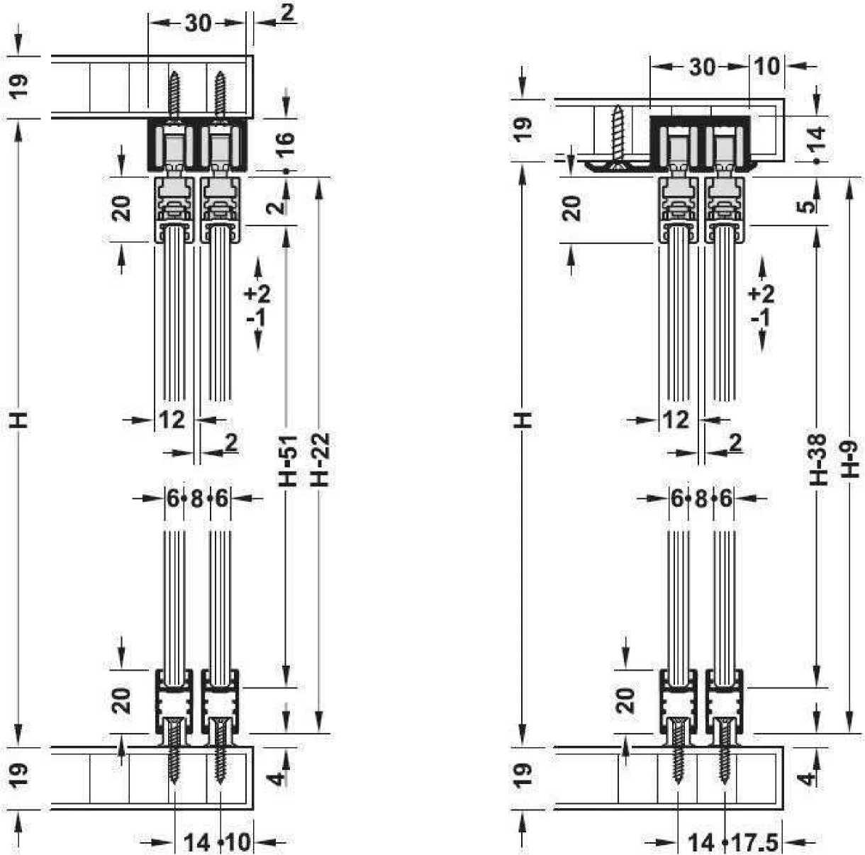
Running gear installation
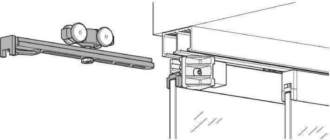
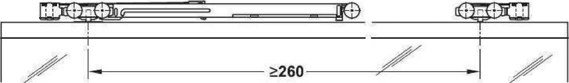
Minimum door width for one soft close mechanisms - 400 mm
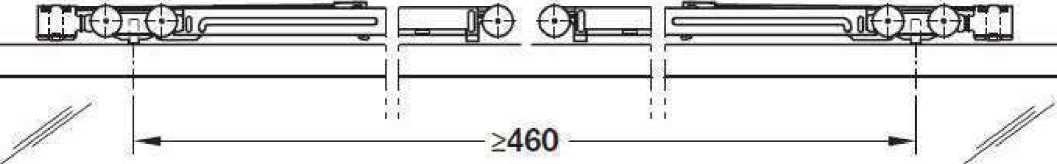
Minimum door width for two soft close mechanisms - 600 mm
Clipo 16 GPPK; with glass fixing profile top and bottom
|
|
|
www.tris.ca.nz 0800 666 556 info@tris.co.nz I0R SYSTEMS Guiding Desigri - Ir nor med Inter ior s | |
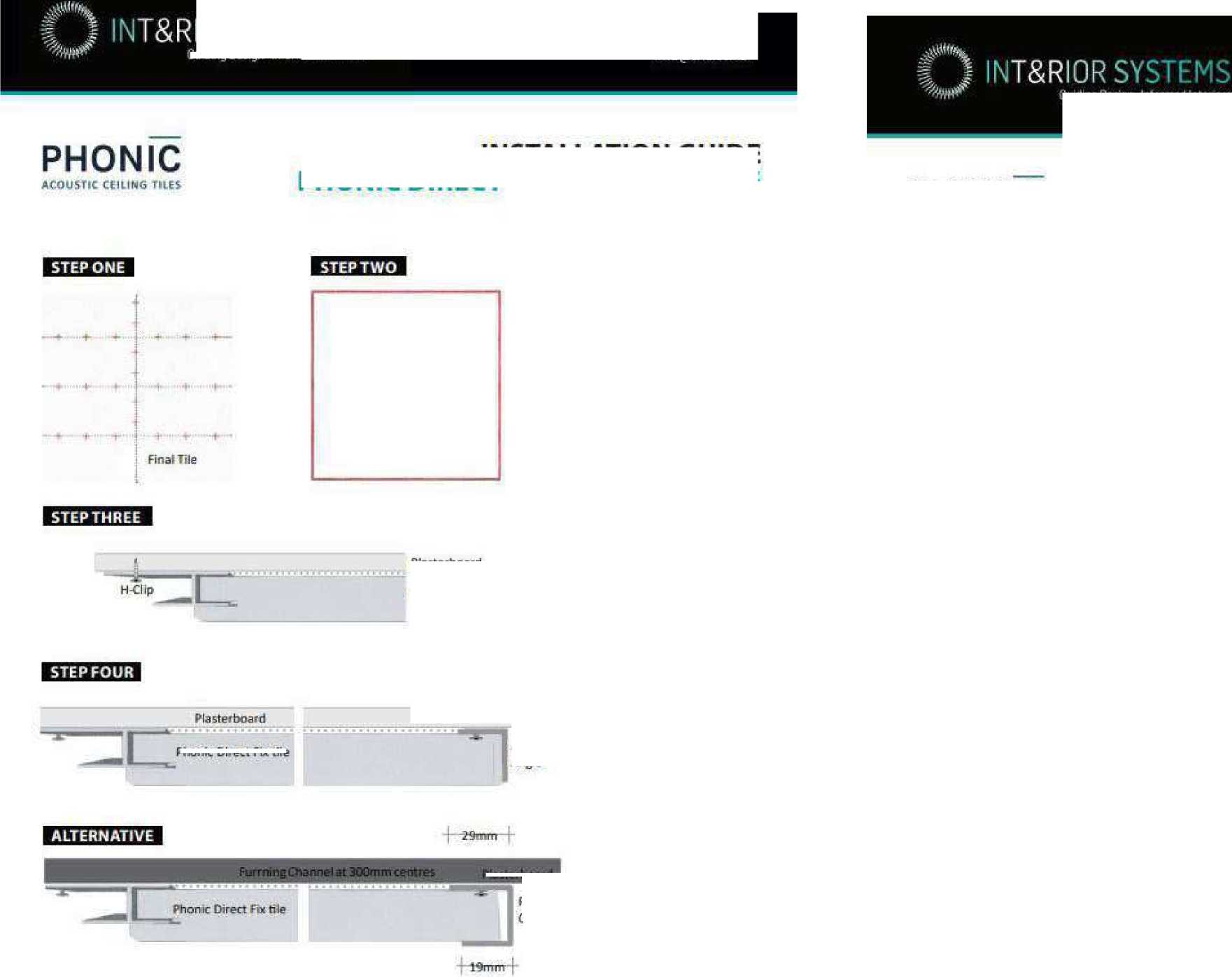
Phonic Direct Fix tile |
Phonic Direct Fix tile |
|
YOU WILL NEED 1200x600 Guiding Design-Informed interiors Please note that whatever the configuration, the final tile will have a maximum of one edge with H clips Perimeter Channel STEP TWO Install an aluminium angle along the edges to create a frame STEP FOUR Apply adhesive and slide the final file into place. Prop until adhesive is dry. PHONIC ACOUSTIC CEILING TUES | |
INSTALLATION GUIDE PHONIC DIRECT FIX FREE-FLOATING
STEP ONE
Determine tile configuration and identify fixing points for the H Gbps on the ceiling. The layout is dependent on the desired configuration, leave the edges tree.
Plasterboard
Aluminium Angle
Plasterboard
IR GRWP
CLIENT
PROJECT
PLAN DESIGN DELIVER
NAENAE COLLEGE
0800 666 5S6 info@trisjco.nz
INSTALLATION GUIDE PHONIC DIRECT FIX ON PLASTERBOARD
Wal I boa rd Adhesive
H-Clip -
C Max Direct Fix Tiles -
STEP THREE
Apply adhesive to the back of the tiles and place the tiles into the aluminium frame. Complete One row at a time and use H Clips to mechnically fix the edges as identified in step 1. Ail files with edges on the perimeter should be propped while the adhesive dries.
INTERIOR UPGRADE OF
ADMINISTRATION BLOCK
ADDRESS
STATUS
600x600
 |
Plasterboard Phonic Direct Fix tile |
DRAWING
Sheet No.
A407
910 HIGH STREET
AVALON
LOWER HUTT 5011
TENDER/CONSENT DRAWINGS
PHONIC CEILING TILES
Scale
@ A3
Date
Drawn By
STEP ONE
Determine tile configuration and identify fixing points tor the H Clips on the ceiling. The layout is dependent on the desired configuration. Ashlar pattern is recommended, especially where the ceiling may not be entirety level. Disucss with T&R interior Systems if you wish to do nonashlar installation.
STEP TWO
Apply a couple of blobs of adhesive to the back of the files and place them onto the plasterboard ceiling. Use H Clips as per layout to secure into place. Complete one row at a time. Please note that there is a small airgap between the tiles and the plasterboard; the adhesive is there as a safety measure only and should not adhere the tile directly onto the plasterboard.
STEPTHREE
Apply adhesive and si de the final tile into place. Prop until adhesive is dry.
AUGUST 2022
JANINE FENELON
This design and drawing is the copyright of IR Group Ltd and is not to be reproduced without written permission.
Do not scale from drawings.
FOR THE TIMBER SLATTED SCREEN IN THE RECEPTION AREA
SYSTEM 1 WILL BE USED FOR THE BASE OF THE SCREENS AND SYSTEM 2 FOR THE TOP OF THE SCREENS
SEE DETAILS FOR BOTH SYSTEMS ON SHEET A409
43 x 90mm BATTENS TO BE USED AT 70mm CRS
BATTENS TO BE AMERICAN WHITE OAK
LENGTH OF SCREENS IN MAIN RECEPTION 1400mm MAX. AND LENGTH OF SCREENS IN STUDENT RECEPTION 1000mm MAX.
HEIGHT OF TIMBER BATTENS TO BE CONFIRMED ON SITE BY CONTRACTOR BEFORE ORDERING MATERIAL
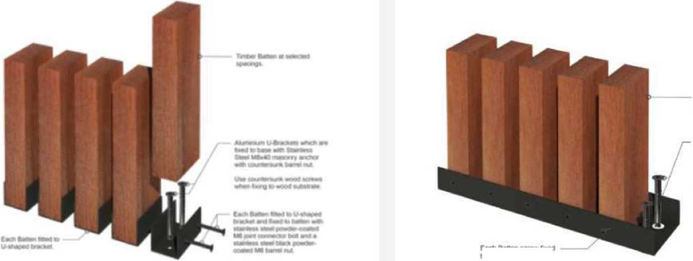 |
Tlnibai Bust it el selected speongs Al<<ww*n U-Ctaroel wnich are tbad to base lb®d wm Stainless Steel M8*40 irwsonr» anefw web countecMink Miwf nut Use countersonn. wood screws when fining Ic wood suMtiate |
|
Each Belta' sci vw lined to. J-shapad channel | |
SYSTEM 1
SYSTEM 2
Individual installation
Base u-channel and top u-channel fixing
Bracket & bolt fixing
Screw fix fixing
|
Batten spacing at your specification |
Batten spacing at your specification |
Individual c-bracket batten support
Top and bottom u-channel fixing and mid height continuous support rod
Each batten [batten, brackets and bolts) will need to be installed individually.
Aluminum top and bottom u-channels are fabricated then black powder-coated. Battens are placed in channels then screw fixed at the desired spacings All dividers are fabricated to the height required
|
IR GR^UP |
CLIENT PROJECT ADDRESS STATUS DRAWING Sheet No. A408 This design and drawing is the copyright of IR Group Ltd and is NAENAE COLLEGE INTERIOR UPGRADE OF 910 HIGH STREET TENDER/CONSENT ZENTHE TIMBER Scale @ A3 not to be reproduced without |
|
PLAN DESIGN DELIVER |
ADMINISTRATION BLOCK AVALON DRAWINGS SCREEN written permission. |
|
027 6222 138 716 Main Road North, Upper Hutt |
Date AUGUST 2022 LOWER HUTT 5011 Do not scale from drawings. Drawn By JANINE FENELON |
SYSTEM 1
U-Bracket
43mm, 70mm & 140mm deep
SYSTEM 2
U-Channel
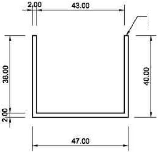
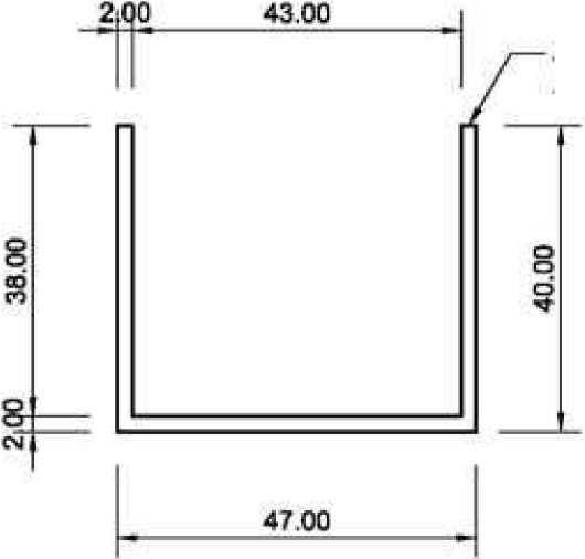
Zenthe Continuous
Aluminium U-Channel
Ze nibs Aluminium U-Bracket
|
IR GR^UP |
CLIENT PROJECT ADDRESS STATUS DRAWING Sheet No. A409 This design and drawing is the copyright of IR Group Ltd and is NAENAE COLLEGE INTERIOR UPGRADE OF 910 HIGH STREET TENDER/CONSENT ZENTHE TIMBER Scale @ A3 not to be reproduced without |
|
PLAN DESIGN DELIVER |
ADMINISTRATION BLOCK AVALON DRAWINGS SCREEN written permission. |
|
027 6222 138 716 Main Road North, Upper Hutt |
Date AUGUST 2022 LOWER HUTT 5011 Do not scale from drawings. Drawn By JANINE FENELON |
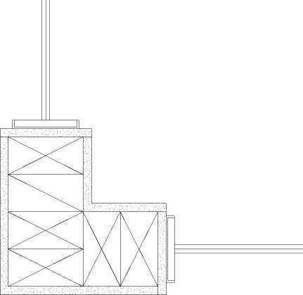

1/A410 PLAN OF FRAMING DETAIL OF CORNER OF OFFICE 7
|
CLIENT |
PROJECT |
ADDRESS |
STATUS |
DRAWING |
Sheet No. |
A410 |
This design and drawing is the copyright of IR Group Ltd and is | |
|
NAENAE COLLEGE |
INTERIOR UPGRADE OF |
910 HIGH STREET |
TENDER/CONSENT |
FRAMING DETAIL |
Scale |
1 : 5 @ A3 |
not to be reproduced without | |
|
PLAN DESIGN DELIVER |
ADMINISTRATION BLOCK |
AVALON |
DRAWINGS |
Date |
written permission. | |||
|
janine@irgroup.co.nz 027 6222 138 |
LOWER HUTT 5011 |
AUGUST 2022 |
Do not scale from drawings. | |||||
|
716 Main Road North, Upper Hutt |
Drawn By |
JANINE FENELON |
SpencerHolmes
engineers - surveyors - plann
STRUCTURAL CALCULATIONS
FOR
ADMIN BLOCK ALTERATIONS
AT
NAENAE COLLEGE 910 HIGH STREET AVALON LOWER HUTT
FOR THE
NAENAE COLLEGE BOARD OF TRUSTEES
Spencer Holmes Limited 57 Willis Street
PO Box 588
WELLINGTON
Phone (04) 472 2261
Design Features Report
Admin Block Alterations
Naenae College - 910 High Street LOWER HUTT
SpencerHolmes engineers - surveyors - plann
-
1 GENERAL
Spencer Holmes Limited has been commissioned by the Naenae College Board of Trustees to undertake structural engineering design services for the proposed alterations at the admin block for Naenae College, 910 Naenae College, Avalon, Lower Hutt.
-
1.1 Building Description
The admin block at Naenae College is a lightweight timber structure on subfloor framing with foundation walls. The proposed alterations involve wall changes and a new entrance way.
-
1.2 Objective
This Design Features Report (DFR) defines the design criteria for the seismic strengthening of this existing building as indicated below;
|
Acceptable Solutions (B1/AS) |
Specific Engineering Design (B1/ VM1 and VM4) |
^ Beams/Lintels/Framing
|
- Geotechnical Engineering Report ^ SED of Foundations ^ SED of Beams/Lintels/Framing
|
-
1.3 Design Standards
The following design standards are applicable to specific engineering design aspects of the building:
Acceptable Solutions (B1/AS)
Verification Methods (B1/VM1 and VM4)
^ Loads: NZS 1170:2002
^ Timber: NZS 3604:2011
^ Loads: NZS 1170:2002
^ Concrete: NZS 3101:2006
- Blockwork: NZS 4229:2013
^ Steel: NZS 3404:1997
- Other:
^ Timber: NZS 3603:1993
^ Blockwork: NZS 4230:2003
-
2 DESIGN LOADS
-
2.1 General
-
The design actions for this building are in accordance with AS/NZS 1170;
Importance Level = 2
Design Working Life = 50 years
-
2.2 Gravity Loads
The table below summarizes the typical material weights used for design.
Timber Steel Concrete
Soil
5.1 kN/m3 78.5 kN/m3 23.5 kN/m3
19.0 kN/m3
The table below summarizes the typical vertical gravity loads used for design.
Usage
Dead Live
Roofs
0.50 kPa 0.25 kPa
Internal Floors
0.50 kPa 1.50 kPa
External Floors
0.50 kPa 2.00 kPa
Timber Walls
0.40 kPa -
-
2.3 Wind Loads
The wind loads on this building have been determined from the Hutt City Council wind maps.
Wind Zone
M (Medium)
-
2.4 Snow and Ice Loads
Snow and ice are not significant loads for this building Region: N1, < 400m
-
2.5 Seismic Loads
The seismic loads on this building have been determined from NZS3604:2011;
EQ Zone
Soil Class
Roof Cladding
Single-Storey Walls
Roof Pitch Degrees
=3
= D
= Light
= Light
= 0-25
(Deep/Soft)
-
3 SERVICEABILITY CRITERIA
Particular elements are designed to the recommended serviceability deflection limits of AS/NZS 1170.0:2002, Table C1.
-
4 SOIL CONDITIONS
-
4.1 Site Soil Conditions and Bearing Pressure
-
Building Usage Details
-
- Ground Conditions Assumed
-
^ Site Investigations Penetrometers, Augers, determined 300kPa Ultimate bearing
Geotechnical Report
-
4.2 Liquefaction & Lateral Spreading
Greater Wellington Regional Liquefaction Hazard - Low
-
4.3 Proposed foundation system
The foundation system specified is concrete piles down to 300kPa ground.
-
5 DURABILITY - B2 COMPLIANCE
-
5.1 Design Life for Durability
-
-
Foundations and Superstructure = 50 years
Non Structural / Cladding = By others
Note: The design of non -structural elements and cladding specification are by the Architects and/or Others and are not covered by this design features report.
-
5.2 Exposure Zones
NZS 3604 = Exposure Zone C (Medium)
-
5.3 Durability Provisions
There is no effective verification method for B2 contained within the Building Code, however we can confirm that for the structural elements shown in our documentation;
-
• B2 Acceptable Solution for Structural Timber
NZS 3602 2003 Chemical preservation of round and sawn timber
NZS 3604 2011 Timber framed buildings
NZS 3640 Part 1:2003 Timber and wood-based products for use in building
Timber treatment is to be selected in accordance with Table 1A of B2/AS1. The timber treatment is to be specified by the Architects and/or others.
-
• B2 Acceptable Solution for Structural Concrete
NZS 3101 Part 1:2006 Concrete structures standards
Concrete covers have been selected in accordance with NZS 3101, Part 1, Section 3.
-
• B2 Acceptable Solution for Structural Steel
SNZ TS 3404:2018 Durability requirements for steel structures and components
Steel protection has been specified in accordance with SNZ TS 3404 Table 6.
-
6 DESIGN DOCUMENTATION
-
6.1 Calculations
-
Analysis of the structural system has completed using a combination of hand calculation, excel spreadsheets, and 2D/3D analysis using Space-Gass computer software.
These calculations are included as part of this Design Features Report
-
6.2 Drawings
Structural drawings have been prepared in hand sketch, and supplied to the client in pdf format.
-
7 CONSTRUCTION MONITORING
-
7.1 Construction Monitoring Level
-
The design is based on the verification of specific design B1/VM1 and VM3 aspects to the construction by a suitably qualified Chartered Professional Engineer in accordance with ACENZ/IPENZ level CM3.
-
7.2 Inspections
We confirm that Spencer Holmes Limited been engaged to undertake construction monitoring to the recommended level above. The following inspections for specific design elements are required to meet this level:
-
^ Pile inspection
-
^ Timber Beams / posts and connections
-
^ Steel Beams / posts / portal frames and connections
Inspection of non-specific design structural elements to NZS 3604:2011 such as floor slabs/foundations, bracing, framing, and simple lintels generally undertaken by the Building Inspector for the Local Territorial Authority.
200384P01
associations consultings engineering
Building Regulation Clause(s) ……B1
PRODUCER STATEMENT - PS1 - DESIGN
ISSUED BY:
Spencer Holmes Limited
TO:
Naenae College Board of Trustees
TO BE SUPPLIED TO: Hutt City Council
IN RESPECT OF:
Admin Block Alterations
AT:
Naenae College, 910 High Street, Avalon, LOWER HUTT
We have been engaged by the owner/ developer referred to above to provide structural engineering and design services in respect of the requirements of Clause(s) NZBC B1 of the Building Code for
All
| ^ | Part only (as specified in the attachment to this statement)
Structural aspects of the works as shown on the Spencer Holmes Limited Drawings stated below
of the proposed building work.
The design carried out by us has been prepared in accordance with Compliance Documents issued by Ministry of Business, Innovation and Employment verification methods B1/VM1 and B1/VM4 and the Approved Documents of the NZBC.
The proposed building work covered by this producer statement is described on the drawings titled Structural Sketch Details for Admin Block Alterations and numbered 200384 B01 (details SK1 to SK8 inclusive) and dated May 2022; together with the specification reference 200384 S01 and dated May 2022, and other documents
set out in the schedule attached to this statement.
On behalf of the Design Firm, and subject to:
-
(i) Site verification of the existing structure, and the minimum ultimate ground bearing capacity to
300kPa under all foundations or as per the drawings,
-
(ii) specific design elements of structure and other assumed design criteria stated on drawings being
confirmed by a Chartered Professional Engineer to a construction monitoring level of CM3.
-
(iii) non specific aspects of structural design complying with the requirements of NZS 3604:2011, for a
“Medium” wind speed zone,
and
-
(iv) all proprietary products meeting the performance specification requirements;
I believe on reasonable grounds that a) the building, if constructed in accordance with the drawings, specifications, and other documents provided or listed in the attached schedule, will comply with the relevant provisions of the Building Code and that b), the persons who have undertaken the design have the necessary competency to do so. I also recommend the following level of construction monitoring/observation:
CM1 CM2 CM3 CM4 CM5 (Engineering Categories) or as per agreement with owner/developer (Architectural)
I, Hayden Daniel Milburn am registered as: 0 CPEng Number: 1022071
I am a Member of: ^| ENGINEERING and hold the following qualifications: BE (Hons), CMEngNZ
NEW ZEALAND
The Design Firm issuing this statement holds a current policy of Professional Indemnity Insurance no less than $500,000*. The Design Firm is a member of ACENZ.
SIGNED BY Hayden Daniel Milburn ON BEHALF OF Spencer Holmes Limited
|
DATE 30th May 2022 |  |
(Signature)
Note: This statement shall only be relied upon by the Building Consent Authority named above. Liability under this statement accrues to the Design Firm only. The total maximum amount of damages payable arising from this statement and all other statements provided to the Building Consent Authority in relation to this building work, whether in contract, tort or otherwise (including negligence), is limited to the sum of $500,000*.
This form to accompany Form 2 of the Building (Forms) Regulations 2004 for the application of a Building Consent.
SpencerHolmes
engineers • surveyors -planners
Project n^G PAtcOU-tC^-AOwP^jiL^^
| ||||
|
□ate m/v icxz Job Ref . -^UM | ||||
Description Kjw itP
u^tiO^rTp^G S\k^C(i.vaftL t^or-OrStZ» FOa Th^ A.vxG^^I lOO i <^f<
-tv\G ^O/^S^t Jrv««A.TxOJ I^US^V- ®V c^^ero^G- COuUGQ.^^
O&^l&o TO I>JC.u>oG
BQ/\flKiCt tiV'^GcVO
CpkjOPt Oe.VrG«x> ^r^t^ 0g^1G»*\J
ST^ c.OxJOTTtOkJ^>
GCk 2^^ S iSSU. OASJk O r^&rJ.O^ Vj» )G "Soots SOOta.0^ CiOZ.OiMx,^ fST AJpP^Gxx/v^SV&kM 2.7<-
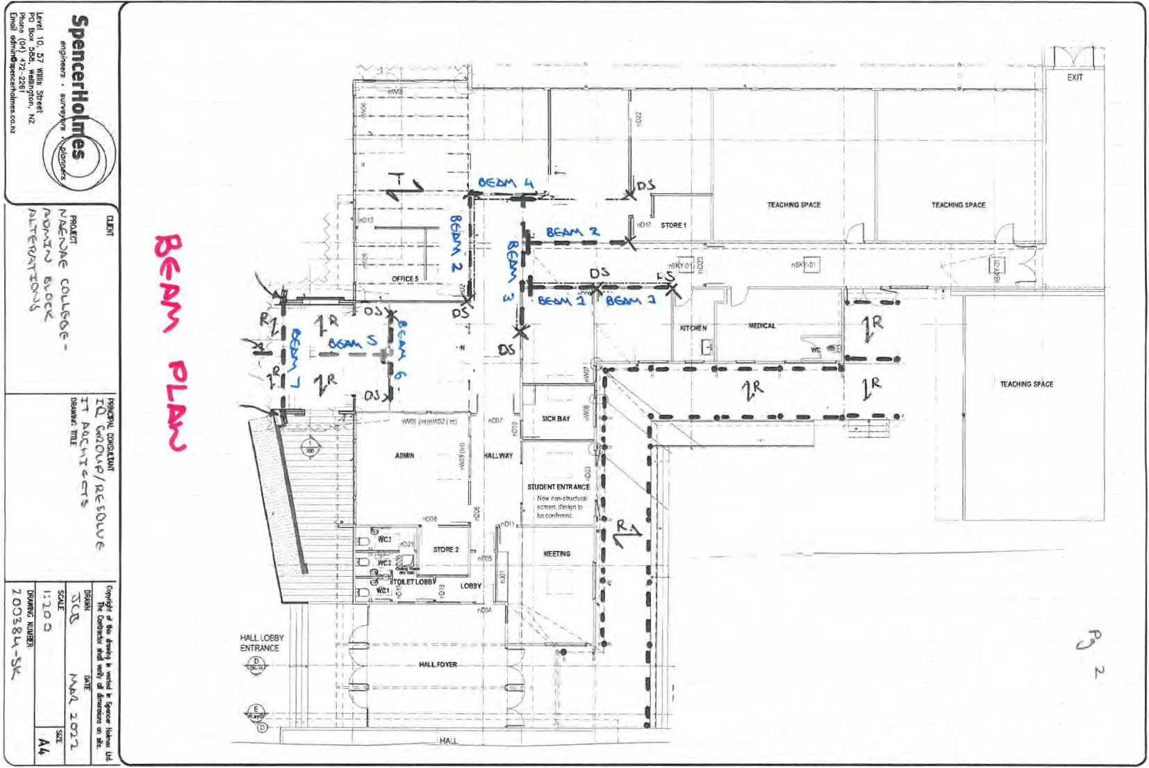 |
|
^fS@#®gf MAMA^EMĒMT" IL A M @ PL A NN 0 N ® - B^^^l^i^l® ° ^ T l^ ULI Q Ī HI ^ ^ IL - @ II VII IL = F S ® S |
|
BEAHSgl Alisea Uniformly roof floor wall Point Dea External V (ULS) (SLS) Point Win UMQ QQl (ULS) (ULS) (ULS) (ULS) ULTIMAT * M* = TRY. Moment C SUPPORT (Reaction tULS) (Reaction (ULS) 11' Shear Cap samcfz Limit Defle Distance tc CHECK: Defies! inn Vibration |
rjl£i ®#jj ^ ^udl AAAAAAAAAAAAAAAAAAAAAAAAAAAAAAAAAAAAAl |
G* & Qw IAAAAAAAAAAAAAAA.A | |
|
A B ā = 0 mm |
z b = 3800 mm |
c
0 0 kN/m 0 0 KN/m
0 0 kN Max Downward [ Tables 5 1.5 2 & 6.3 )
0.0 KN 0.0 kN t 0.0 kN k3 = 2.0 + 0.0 kN y, = 04 + 0,0 kN V, = 0.7 + 0 0 kN
MPa x 103 mm" A toW? kNm kNm OK 2 4 kN 5 7 kN 4 0 kN
-2.3 kN 10 6 kN
-2.3 kN 10.0 kN kN kN OK 48El>x1(3a/l)-4(a4)‘| OK OK OK OK | |
|
1 - 3800 mm |
1 : | ||
|
Distributed Dead Loads: Uniformly Distributed Live Loads: 0 50 kPa x 5 00m = 2 5 kN/m roof: 0 25 kPa x 5.00m - 0.50 kPa x 0.00m = 0 0 kN/m Ext floor: 2.00 kPa x 0.00m - 0 35 kPa x 0.00m = 0.0 kN/m 1 nt floor 1 5 0 KPa a 0 00m - beam self weight = 0.1 kN/m 6^1= 2.6 KN/m 0^ = d Load GM = 0.0 kN Point Live Load: Qrl = Wind Loads: Max ii^warri ( TablasR 1,R 2 S 5 $) External Wind Loads; 1.50 kPa x 5.00m x -0.9 = -6.8 kN/m x 0.4 = 1.05 kPa a 5 00m x -0.9 - -4.7 kN/m x 0.4 = d Loads: W«.ws 0,0 kN ¥¥«.*» = W.^« 0-0 kN Wt.w = ^ŌĪNATĪOHS: 1.35G = 3.5 kN/m ♦ 0.0 kN (SLS) HaGi^G = 5.8 kN/m 12G&1,50 = 5 0 kN/m »0 0 kN (SLS) G & mlQ - 3.5 kN/m 0 9G8W„= 4 4 kN/m +0.0 kN (SLS) G8yi,O8W, = 8 2 kN/m >2G8W„ = 6.2Wm ♦ O.OkN (SLS) G 8 yi,Q 8 W, = 56kN/m F LIMIT STATE: wF/S + Pab/I = 11.1 kNm M" = 2(300x45 HySpan Clear Span, 1 3800 mm mm fez 90 mm E = 13200 3= 300 mm Z~ 1350 4= OS l.i 202 5 k, = 0.8 k>= 1.0 fb- 48.0 MPa apaoity: ®M„=®klMfbZ * 41 s »= 11,1 reactions; it A) Ga s 5.0 kN (Reaction at A) 0* = W.,...,A = -12.8 kN Wuo^ = Wx^A = -0 0 kN W.«* = 1.35G = 6 7 kN (SLSi k/JS^.Q = 12G815Q * 9,6 kN • G 8 V.O - o 9G a w„ - -a.3 kN g a y,o a w, = 12G8W„ = 11 7 kN GaysQSW, = it C) Gr - 5.0 kN (Reaction at C) Qc = Wbdac • -12 8 kN «...,£ = W^a - -SOHN Wt>#lC= 1.35G = 67kN (SLS) ksG 8 <yO = 1 2GS 1 50 = 3 6 kN " 6 8^0 = 0 9G & W„ = -8.3 kN '■ G 8 VsQ 8 W, = «2G8W„ = 11 7 kN ” G8v.Q8W. = salty: ®V„= ® kl fs 0.67 A = 614 « 11.7 ABILITY LIMIT STATE: ction to Span / 300 = 12.7 mm A = (5 w 1* / 384 E 1) . ( P P Wall 1300 — 30 0 mm d — 9000 mm lim>= 91.0 x 10E mm1 27300x45 1,- 202.5 x 10* mm' A' = 2.7 mm ( G ) A’ = 5 8 mm ( kjGS i|/|Q ) A’ = 5.7 mm { G 8 y,0 8 W,) (IkN MidSpan, Pin-Pin Supports ) X« - 0 43 mm | |||
|
USE: 2/300x45 HySpan tor Beam 1 | |||
0.43 mm
0/19 mm
0.11 mm
| ||||||||||||||||||||||||||||||||||||||||||||||||||||||||||||||||||||||||||||||||||||||||||||||||||||||||||||||||||||||||||||||||||||||||||||||||||||||||||
|
( G & v*Q & ws ) Vibration (1kN Midspan. Pin-Pin Supports ) OK OK V = A*> = 67 049 | ||||||||||||||||||||||||||||||||||||||||||||||||||||||||||||||||||||||||||||||||||||||||||||||||||||||||||||||||||||||||||||||||||||||||||||||||||||||||||
mm
mm
|
BEAM SETUP: Gudi & Qudl I Gp« & Qpt A A A A A A A A A A A A A A A A A A A A A A A A A A A A A A Aw A A A A A A A A A A A A A A A A A A A A A A a = 3200 mm 1 b = 3200 mm |
0.3 kN/m 0.0 kN/m 0.0 kN/m 0.3 kN/m 6.2 kN Ma» OaMwfflid (Tables 5 152553) 0.7 kN/m 0.5 kN/m 15.0 kN 10 5 kN + 9.4 kN ^sO.4 + 11.2 kN M'.= 0 7 + 12.4 kN + 21.7 kN 48 5 kNm kNm x 103 mm4 x 10* mm4 x 10* mm4 MPa MPa mm ( Table 5 6.3(1)) (Table 5 6.3(2)) (Table563(3) I mm (563 1 ) (Eq 5 S I 1(3)&(4)| (Table 2 6 1*2) kNm | law* 5.61 Id!) kNm OK A 9 kN 9 8 kN
15 8 kN 40 El}x{(3a/l)-4(3/1/) OK OK OK OK |
|
1 - 6400 mm | |
|
LOADS; Uniformly Distributed Dead Loads: Uniformly Distributed Live Loads: roof 0.50 kPa x 100m* 0 5 kN/m roof 0.25 kPa x 100m = floor 0 50 kPa x 0.00m - 0 0 kN/m External floor 2 00 kPa x 0 00m = wall: 0 35 kPa x 0.00m * 0 0 kN/m Internal floor 1.50 kPa x 0 00m = beam self weight = 0 4 kN/m G^i = 0.9 kN/m Q^ = Point Dead Load: G^= 6.9 kN Point Live Load; Qp( • External Wind Loads: Ma# Upward (Tab*» si 5 2 4 5 3) External Wind Loads; (ULS) 1.8 kPa x 1.00m x -0.9 * -1.6 kN/m x 0.4 = (SLS) 1.3 kPa x 100m x -0 9 * -1.1 kN/m x 0.4 a Point Wind Loads: Wu up = -33.8 kN Wu^n • W^ x -23.7 kN WMn = LQ^SQMBINAn^N^ (ULS) 135G = 1.2 KN/m +9.3 kN (SLS) G&yP = 1.0 kN/m (ULS) 12G&15Q = 14kN/m + 176kN (SLS) G&V,Q = 1,0kN/m (ULS) 0 9G&W„ = 0.9 kN/m + 27 6 kN (SLS) G4i|,.Q&Wt = 01 kN/m (ULS) 12G8WU* 1.8 kN/m + 23 3 kN (SLS) G & v.O & W, = 1.5 kN/m ULTIMATE LIMIT STATE: + M* = wl’/8 ♦ Pab/I « 485kNm -M* = TRY: 250PFC ®M„ = 104,0 kNm M..= 116 Clear Span, I 6400 mm d = 250 mm J = 238 b. - 90 mm I, = 3.64 k= 15 mm l,= 35.9 t, = 8 mm G = 80000 n» = 1 E= 200000 Segment Length: L = 3200 Twist Restraint k,= 1.13 Load Height: k,- 2.00 Rotation Restraint k.= 1.00 Effective Segment Length: L, = k,k,k.L = 3612 Reference Buckling Moment. Ml = 116 kNm o. = 0.601 Moment Modification Factor s« - N/A o.„ = 1000 Moment Capacity: PM„’o,a,«M„ = 62.5 >= 48.5 $Ue£QSI-R£AQHQttSl (Reaction al A) Ga = 6 2 kN (Reaction at A) O. a Wo».* * -22 1 kN WM^A = W.^,» - -15.5 kN W,^A = (ULS) 1 35G - 8.4 kN (SLS) G 4 iwQ = “ 12G415Q = 13.3 kN " G 8 v,Q = " 0 9G8W„ = -16 5 kN * G4k>,Q4W, = ” 1.2G4W„ = 17 3 kN ’ G&m.Q&W. = (Reaction at C) Gc = 6.2 kN (Reaction at C) Qt = W.»c = -221 kN W^x W««e = -15 5 kN W,.<i„.c» (ULS) 1.35G * 8.4 kN (SLS) G4wQ = 1.2G8 15O = 13 3 kN ” G 8 v,Q = ” 0.9G4W„ = -16 5 kN * G 4 v,Q & W, = “ 1.2G&W„ = 173kN * G&V.Q4W, = SERVICEABILITY LIMIT STA TE: Limit Deflection Io Span / 300 = 21,3mm A - ( 5 w I* / 384 E I) + (P l’/ Distance to Wall / 250 = 18.8 mm d = 4700 mm steel. 1^-,»= 40,6x10’mm‘ TRY: 250PFC I, = 451 x 10* mm* Deflection: A" = 6,3 mm (G) A* = 8 0 mm ( G & vO ) A* = 16.9 mm ( G & v,Q 4 W.) Vibration (1kN Midspan. Pln-PIn Supports) A» - 0 61 mm | |
|
USE: 250PFC for Beam 3 | |
BEAM SETUP;
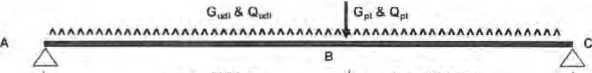
|
LOADS: Uniformly Distributed Dead roof: 0,50 kPa k floor: 0,50 kPa x wall: 0.35 kPa x beam s |
a = 2600 mm |
b~ 1200 mm |
0 7 kN/m 0 0 kN/m 0 0 kN/m 0.7 kN/m | |
|
1= 3800 |
mm | |||
|
Loads: 2 70m- 1.4 kN/m 0 00m = 0.0 kN/m 0 00m = 0 0 kN/m elf weight - 0,2 kN/m 6^= 1.6 kN/m |
Uniformly Distributed roof: 0 25 kPa x External floor: 2 00 kPa x Internal floor: 1 50 kPa x |
Live Loads. 2 70m = 0 00 m - 0 00m - Ow “ | ||
|
Point Dead Load: |
G^ = 6.2 kN |
Point Live Load |
O„- |
3 d kN |
|
External Wind Loads: |
Mar Upward | Tables. Ē,1,5,2 5 5,3 ) |
External Wind Loads: |
Max Downward ( Tables 5 1,52 S 5.3 ) | |
|
(ULS) 1.8 kPa x |
2.70m x -0.9 = -4.4 kN/m |
X |
0.4 = |
2.0 kN/m |
|
(SLS) 1.3 kPa X |
2 70m X -0.9 = -3.1 kN/m |
X |
0.4 * |
1.4 kN/m |
|
Point Wind Loads: |
W„ „„ = -22.1 kN |
wM„= |
9.8 kN | |
|
W, ^ = -15.5 kN |
«•>.= |
6.9 kN | ||
|
LOAD COMBINATIONS: | ||||
|
(ULS) 1.35G = |
2 1 kN/m + 8 4 kN (SLS) |
G & wiQ = |
1 9 KN/m |
♦ 78 kN m,-04 |
|
(ULS) 12G815Q = |
2 9 kN/m + 13 3 kN (SLS) |
G & qlaQ - |
2 1 kN/m |
+ 8 9kN M., = 07 |
|
(ULS) 0 9G&W„ = |
3 0 kN/m + 16.5 kN (SLS) |
G&^Q&W, = |
1 0 kN/m |
+ 6.5 kN |
|
(ULS) 12G&W„ = |
3.9 kN/m * 17,2 kN (SLS) |
G8.|nQ8W, - |
3 4 kN/m |
+ 15 8 kN |
|
iLkllMAILLIMJJ^STATE: | ||||
|
+ M‘= wl!/8 + |
Pab/I = 211 kNm |
# = |
10 0 kNm | |
|
TRY: 2O0PFC |
♦M*= 55.0 kNm |
Mu = |
61 |
kNm |
|
Clear Span, 1: |
3800 mm d 4 200 mm |
J = |
101 |
x 10' mm4 |
|
b, = 75 mm |
ly- |
1 65 |
x 10“ mm‘ | |
|
t. = 12 mm |
U' |
10 6 |
x 10' mm' | |
|
U = 6 mm |
G = |
80000 |
MPa | |
|
'V = 1 |
E = |
200000 |
MPa | |
|
Segment Length. |
L = |
3800 |
mm | |
|
Twist Restraint |
k,- |
1.11 |
(Table 5 6 3(1)) | |
|
Load Height: |
k| = |
200 |
(Table 56.3(2)) | |
|
Rotation Restraint: |
L = |
1 00 |
( Table 6.6.3^) | |
|
Elective Segment Length |
Lc- k(ktkfL |
= |
4200 |
mm (563 1 ) |
|
Reference Buckling Moment: |
Ma = 41 kNm |
Qa = |
0479 |
( Eq 5.6^ 1(3)& (4J ) |
|
Moment Modification Factor |
P. = N/A |
t^ = |
1 000 |
( 1 «016 5.6-1 & 2 ) |
|
Moment Capacity: |
OM„ = am a, ^Mv |
26.4 |
kNm (Tubb 5,6 Tift)) | |
|
21.1 |
kNm OK | |||
|
SUPPORT REACTIONS: | ||||
|
(Reaction al A) |
Ga = 5 0 kN |
(Reaction al A) |
Ox = |
2.5 kN |
|
W„„,,A = -154 kN |
WydoA' |
6.8 kN | ||
|
W..„„* = -10.8 kN |
«..■„,*’ |
4 8 kN | ||
|
(ULS) |
1.35G = 6.7 kN |
(SLS) |
G & mQ = |
6 0 kN |
|
1 |
,2G & 1.50 = 9.7 kN |
n- |
G & H^Q - |
6 7 kN |
|
0 9G 8 Wk = -10 9 kN |
“ G 8 t,Q & W, = |
-4 0 kN | ||
|
1.2G8W» = 12.8 kN |
G 8 T,O a w, = |
11.5 kN | ||
|
(Reaction at C) |
Gc = 7.3 kN |
(Reaction at C) |
Qc = |
4 0 kN |
|
W.^ c ° -23.5 kN |
Wu^c- |
10.4 kN | ||
|
W,,w,c - -16.5 kN |
WM„.0 = |
7 .3 kN | ||
|
(ULS) |
1 35G = 9 8 kN |
(SLS) |
G & ip Q = |
8.8 kN |
|
’ 1 |
2G8 15Q = 14.6 kN |
G & v$Q = |
10.0 kN | |
|
if |
0 9G 8 W„ = -17.0 kN |
• G & i|isQ 8 W, = |
-6 4 kN | |
|
0 |
12G8W. = 19.1 kN |
“ G&m/.Q&W. = |
17.3 kN | |
|
SERVICEABILITY ljmitSTATE: | ||||
|
Limit Deflection to Span / 300 |
~ 12*7 mm |
A • (5w I' / 364 |
E I) + { P I3 / |
48 E I} x | (3a/i| -4(a/i)!) |
|
Distance to Wall / 250 |
= IB.8 mm |
d = 4700 mm | ||
|
steel. |
IjUlW |
9 2 k106 mm4 | ||
|
TRY: 200PFC |
lx' |
19 1 x 10' mm4 | ||
|
Deflection |
A*® |
2.6 mm ( G ) |
OK | |
|
d' = |
3.1 min ( G & ihQ ) |
OK | ||
|
A'= |
6 1 mm ( G 8 wtQ & |
W. I |
OK | |
|
Vibration {1kN Midspan, Pin-Pin Supports) Au,, = |
0 30 mm |
OK | ||
USE: 200PFC for Beam 4
SPACE GASS 12.85 - SPENCER HOLMES L ID
31 May 2022. 9 01 AM
Load cases:
■ 13 ----- 1.2G+W.D0WN UL3
 |
|
130.10) |
IaLS unw^t^g»
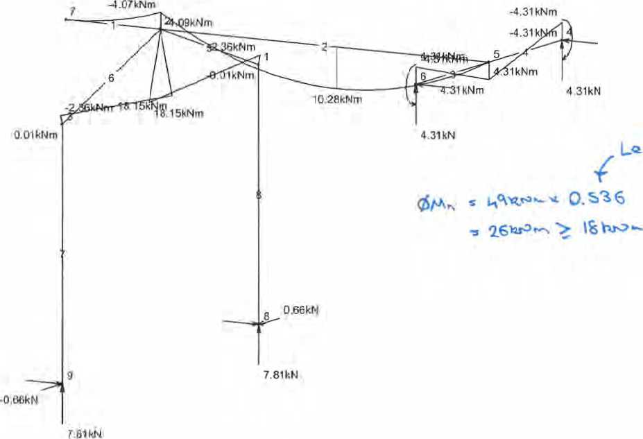
CP’-jT. $<y An 7v £
Materials:
■ 1 STEEL
■ 2 F22 Ash HW S
£eb>\ \(> df^Q -t
Job: G A2020jobs1200380-99\20G®4\Catts\Beam 5 & 6
Units - Len: m, Sec: mm, Mat: MPa, Dens WiA3. Temp Celsius, Force: kN, Mom: KNm Mass T, Acc: g's. Trans: miTh Stress: MPa Scales • Frame: 1.56, Load: None. Disc; None, Moment: 1, Shear: None. Axial None, Torsion None
SPACE GASS 12,85 - SPENCER HOLMES L TO
31 May 2022. 6 04 AM
Load cases;
-
■ 22 ------- G+Wu.ctovvn
Sui uMni^G
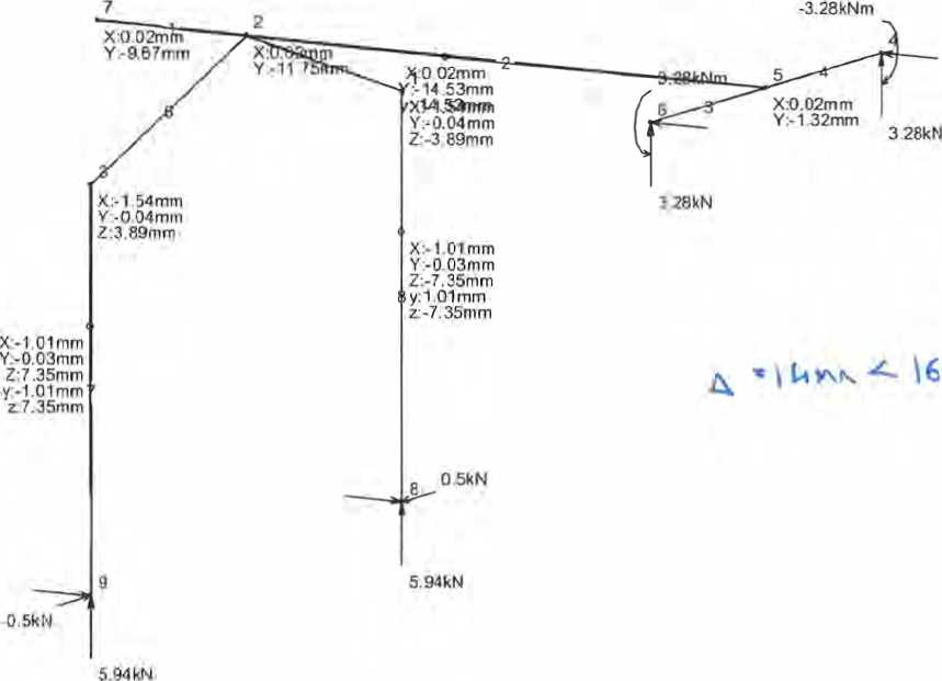

o\<
Materials:
-
■ 1 STEEL
-
■ 2 F22 Ash HW S
Job: G42020jobsl200380-99\200384tCalcs1Beam 5 & 6
Units - Len m, Sec. mm Mat: MPa, Liens; Tm^, Temp: Celsius, Force: kN Morn kNm, Mass, T. Acc gs. Trans: mm, Stress: MPa Scales - Frame: 1:56, Load: None, DiSja 1 Moment: None, Shear. Hone, Axial: None, Torsion: Hone
SpencerHolmes
engineers- surveyors -planners
Project /O^M Aô, COULg-C»C - ^ JA^^Uj fcuZ*- ^ ACVg.R/s^ t<yj \
Description \&GP VC C^r^J^ft^T^O^
J^OPFC CG^^GCTTlOtO
U,0"7 mo^
2 % C WN ^ v ^o^x Z
SJUrOf^ *~ Ml6 800’S US&O IkJ CauC^lxttTo^
1
W& &ft£>ôe t.S fioers
Page
By
fee
Date
MAX 2 04'1
Job Ref
2 00”^
SpencerHolmes
engineers - surveyors -planners
Description iitk&OiR Cr
Page IO
By
Date rjyi 7 0-17.
Job Ref
L lOO^tA
^ix^I^^
SRcxCt RurO<tTTOrO To ^0 UJOJUfc’ TA&U TvA^ GXI^^MG ^flRC^0£. AOV^ttTOkJ To <^ BR^ ^q To N 2:^606^ 20 W. vom-U^ QCrAOvQ-Q A&G TO &R k^xQ/^o KT LaBU/Ax.
KN GoTUna iOTRo to
GO 2:0^^ %
SOIL CLAS^ ^
£O< R gj^C LRG. D gaaA rO O
bJ i^6OU: XO\\ —t Th^vG C,.^ -o- UlCrWT l*0OC'--4> LICAaT vJ^i^
—^ O-7V
|
TOTtsA- ^^Ks ftOOto |
~ tl.SrAX fe.S>|v ' ZA-^ |
|
STiROLR sTorj^V v^kk_^ |
- UFM/^K-m^^\ |
|
EXtAaAi- JC AUuOt^G ^.OO V |
» Z-iO^BkAA 3K ^lA = 2S2I6R |
|
OtAM^j^c £<vl.oSS «oo C |
* 1Z$\GM * $\°\<\A * TfeOOteAA |
o J as
 |
HKaaI^it^ |
3
^gigrt * ^ow^a rrW'
|
m^ + STAIRS -® CORRIDOR CP Easing windrwi md ^*1 eiWFisK © |
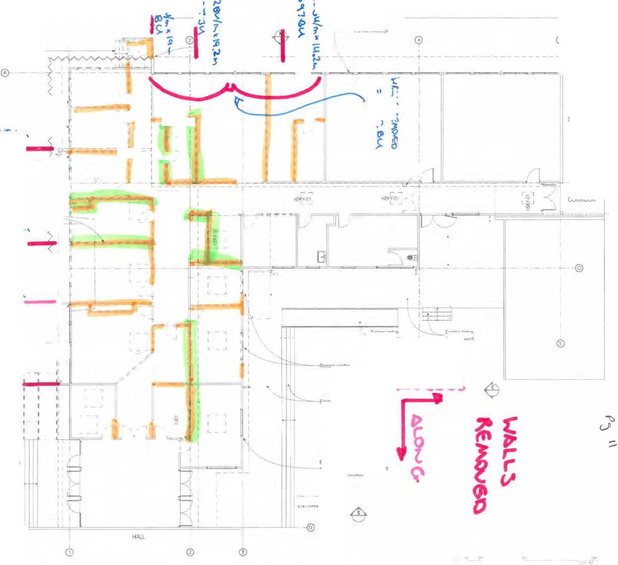
F nSKV.ni |
|
Wr wiwm © p! HALL LOBBY ENTRANCE |
’rav^. re* ,’tog ptaLh. .........tonein^idticc
JfcOfeSA
"Hr
p
o
ft
U'LfejJ ^ '^. V^n
TU^kA
uirW^x it*~
ŪTiA^
. wKling lira» xr^vh^r^nxt
®
EilSUra »nrfiRS npcAte'd Kilts
c U^60/^*l.U»>\ u»-
j lO^A
EXBl*!p lnrter det* wd, Stam
E«Glr^ Airflows ard wsll flmldirq
—WtuirlCd and Mifaiit*srn«l In* hxjiwI Urtess rated othwwiHj
HAL_ LOMY ENTRANCE
Plan - Ground - Exist/Demo
A«O$S
 |
|
EXIT |
4-®
Un orntaK *M mrtrm 4 rmttcr* «to taTSratrs tri rt’h'WBfrarjMncMr wift fti»««»*n#rticmr/' rtjwrtja Corarfcr a n nptsi j> dsotpras to »• anrtirr htwhUW» Plant fa ^ ^ to or)>jfr*ri wtt Ite sfM-Jkatort W «nw r® repxatttey 'n ^ tr#rips rata ft th<Mi«ti*nrTrti
 |
|
M« «MWft |
 |
|
LEVEL 1. 171 VIVIAN STREET TE ASO PQ BOX B7W. WELLINGTON ' i ARCHITECTS CO |
Naenae College
I" «71HJ
Naenae College
Administration Exterior
* |pd Mw
9to High Sired Avalon Hutt div
Plan - Ground -Existlng/Demc
■ OHAFT ■ Dmim &> wy-. IW/.W2
100 P-04
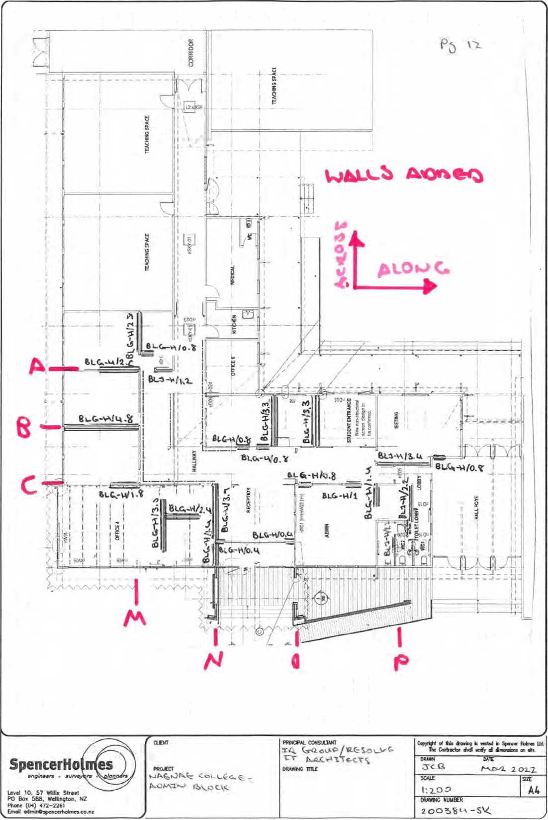 |
^g^©^^&^ MAM$®ĒMl£Mir- IL A IM & P IL A M M II IM ® - BMffiWSWIllM® • ^T^^^^^K^L = & II V 11 L ° F I % Ē |
|
Spencer Holmes |
Pate |
ft | ||||||||
|
Sv |
JCB | |||||||||
|
Propel |
Naenae College |
Date |
31/05/2022 | |||||||
|
Description |
Wall Bracing |
\^j&6 Rei |
2_OOA%v |
A | ||||||
|
Bracing Demand |
Along |
Across | ||||||||
|
Wind: |
BU | |||||||||
|
Earthquake: |
2521 |
2600 BU | ||||||||
|
Height of Level |
4-4 >TT |
Bracing direction- |
Along | |||||||
|
bU/m limit |
U08U/m | |||||||||
|
Wind |
Earthquake | |||||||||
|
Bracing line |
No of Elements |
Bracing member |
Wall height |
Type |
Length |
BU's/m |
Bu's/m adj |
BU |
Bu’s/m adj |
BU |
|
A |
$ |
1 |
2.4 m |
RiG-H |
16 m |
150,0 |
120.0 |
312.0 |
120.0 |
312.0 |
|
2 |
14 m |
BU-H |
1.2 m |
125.0 |
120.0 |
144.0 |
105.0 |
126.0 | ||
|
3 |
2,4 m |
BIC- H |
o,8m |
110.0 |
110.0 |
88.0 |
115.0 |
92.0 | ||
|
B |
s |
J |
2,4 m |
BL&H |
4,em |
150,0 |
120.0 |
576.0 |
120.0 |
576.0 |
|
2 |
2.4 m |
BtG H |
O.Bm |
110.0 |
110.0 |
88.0 |
115.0 |
92.0 | ||
|
3 |
2.4 m |
BU-H |
34 m |
125.0 |
120.0 |
408.0 |
105,0 |
357,0 | ||
|
4 |
2,4 m |
BU-H |
0,8 m |
90.0 |
90.0 |
72.0 |
100.0 |
80.0 | ||
|
5 |
2.4 m |
mr..h |
n n m |
110.0 |
110.0 |
88.0 |
115.0 |
92.0 | ||
|
t |
A |
1 |
2.4 m |
BLG H |
24 m |
150.0 |
120.0 |
288.0 |
120.0 |
288.0 |
|
2 |
2.4 m |
BUS-11 |
16m |
150.0 |
120.0 |
216.0 |
120.0 |
216.0 | ||
|
3 |
2-4 m |
BLG-H |
04 m |
110.0 |
110.0 |
44.0 |
115.0 |
46.0 | ||
|
4 |
2.4 m |
BUS ■ |
0.4 m |
110.0 |
110.0 |
44.0 |
115.0 |
46.0 | ||
|
S |
24 m |
616 H |
OB m |
110.0 |
110.0 |
88.0 |
115-0 |
92.0 | ||
|
$ |
24 m |
BLb II |
11 0 r»i |
110.0 |
110.0 |
110,0 |
115.0 |
115.0 | ||
|
Total |
2566.0 BU's |
2530.0 BU's | ||||||||
|
Demand |
0.0 BU's |
2521.0 BU's | ||||||||
|
WDIV/Ol |
100.4% | |||||||||
|
Spencer Holmes ) r^finrm »u<w^p»» pro>M»f> | |||||||||
|
6» |
KB | ||||||||
|
Project |
Naenae College |
bate |
31/05/2022 | ||||||
|
Detcrlprion |
WAI! FT racing |
\^ Job Ref |
2OoU;q J | ||||||
|
Bracing Demand |
Along |
Across | |||||||
|
Wind; |
BU | ||||||||
|
Earthquake. |
2521 |
260C BU | |||||||
|
Height of Level BU/m limit Bracing line |
74m 120 W/m No of Elements |
Bracing direction: Bracing member |
Across Wall height |
Type |
Length |
Bracing directionWind BU's/m Bu‘s/m ad) |
BU |
Earthquake Bu's/m adj BU | |
|
M |
2 |
1 2 |
2.4 m 2.4 m |
91641 BIG H |
33 m 18 fi» |
150.0 1500 |
120.0 120.0 |
4200 336.0 |
120.0 420.0 120.0 336.0 |
|
N |
1 2 |
24m 2.4 m |
BL^H 61644 |
19 m 1 4m |
150.0 150.0 |
120.0 120.0 |
468.0 168.0 |
120.0 468 0 120.0 168 0 | |
|
5 |
i 2 |
2 4m 2.4 m |
fit A H m*H |
aim 33 m |
150 0 150.0 |
120.0 120.0 |
396.0 396.0 |
120.0 396.0 120.0 396.0 | |
|
p |
1 2 a |
2.4 m 2.4 m 2 4m |
au-H “1 l"H |
2 2m 1.4 m 17 m |
125.0 150.0 125.0 |
120.0 120.0 120.0 |
264.0 168.0 144.0 |
105.0 2310 120.0 1680 105.0 1260 | |
|
Total Demand |
2760.0 BU's 0.0 BU's #DlV/0! |
2709.0 BU's 2600.0 BU's 104.2% | |||||||
|
z <o z w CD CD ° CD 3 X 3 CD — CD CD CD CD o ° CD CO CD CD CD 00 o CD Q. O -^ H c & CD CD W |
|
"0 70 -* O CD m |
|
Number of Blows |
Depth (mm) |
Penetration (mm/blow) |
|
0 |
0 |
0 |
|
5 |
100 |
20 |
|
15 |
190 |
9 |
|
25 |
310 |
12 |
|
35 |
450 |
14 |
|
37 |
560 |
55 |
|
43 |
670 |
18 |
|
53 |
810 |
14 |
|
55 |
950 |
70 |
|
58 |
1100 |
50 |
|
63 |
1200 |
20 |
|
73 |
1440 |
24 |
|
76 |
1590 |
50 |
|
81 |
1730 |
28 |
|
86 |
1850 |
24 |
|
91 |
2020 |
34 |
|
101 |
2200 |
18 |
|
106 |
2330 |
26 |
|
109 |
2460 |
43 |
|
112 |
2610 |
50 |
|
117 |
2760 |
30 |
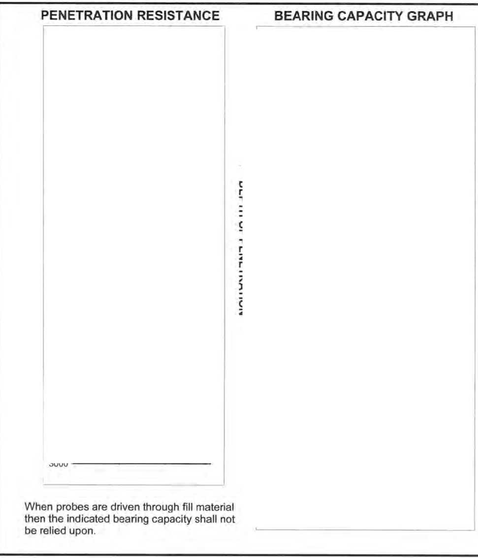
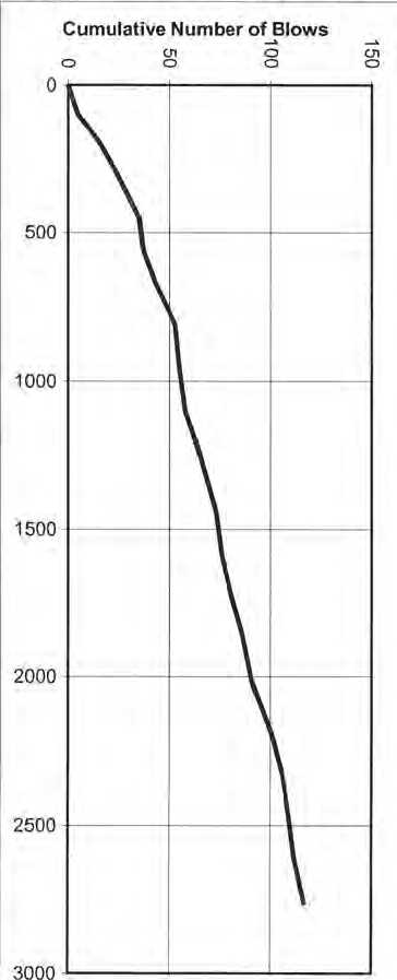
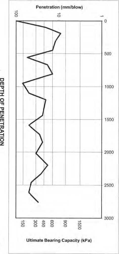
|
UI I 2 i X o . U\JU)J m h *o r-9 O 9 e. 5 w • ” y 2 O O x o =L ® 8 3 Ī 1 f 1 ”2 ~ S « ® u> s 8 § i 0 " 3 N © 0 p N |
|
Z <0 Z <2 ® ° m m ® “ ® w o 3 <0 <0 ® to 3 •• ® o tn 2 o Q. O —I w C 2 £ 7 ® K ® M « |
|
-n m 5 ° M O o 00 K S 00 m j» |
|
Number of Blows |
Depth (mm) |
Penetration (mm/blow) |
|
0 |
0 |
0 |
|
10 |
150 |
15 |
|
20 |
320 |
17 |
|
30 |
640 |
32 |
|
35 |
880 |
48 |
|
38 |
1070 |
63 |
|
43 |
1170 |
20 |
|
48 |
1270 |
20 |
|
53 |
1410 |
28 |
|
63 |
1680 |
27 |
|
68 |
1880 |
40 |
|
73 |
2030 |
30 |
|
83 |
2190 |
16 |
|
93 |
2420 |
23 |
|
103 |
2630 |
21 |
|
108 |
2750 |
24 |
PENETRATION RESISTANCE
|
Cumulative Number of Blows |
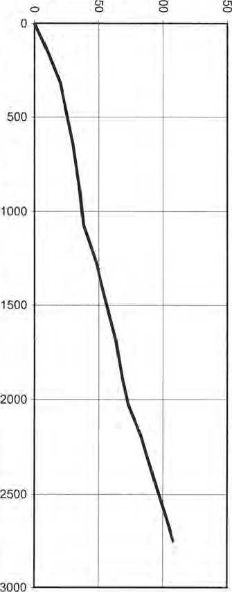 |
When probes are driven through fill material then the indicated bearing capacity shall not be relied upon.
m
O
m z m
33
O
BEARING CAPACITY GRAPH
|
Penetration (mm/blow) |
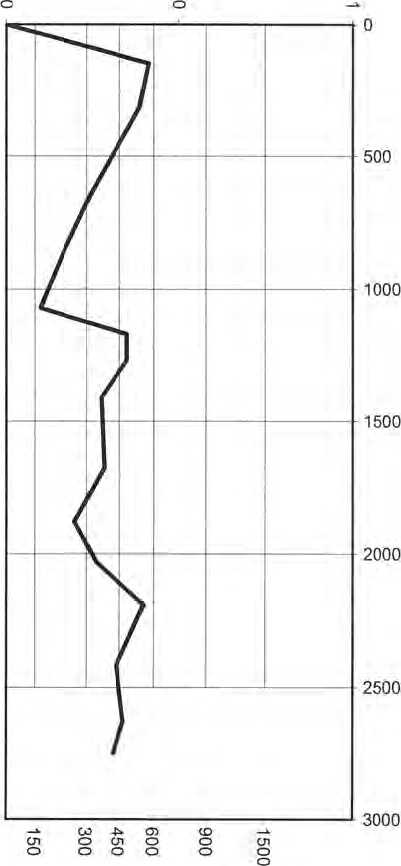 |
|
Ultimate Bearing Capacity (kPa) |
|
Z <0 z ® ® □ T □ M — SU ® <Q ® S 5 »• <0 at o 0) H CL O |
|
Number of Blows |
Depth (mm) |
Penetration (mm/blow) |
|
0 |
0 |
0 |
|
10 |
180 |
18 |
|
20 |
280 |
10 |
|
25 |
380 |
20 |
|
30 |
510 |
26 |
|
35 |
680 |
34 |
|
45 |
1070 |
39 |
|
55 |
1240 |
17 |
|
65 |
1400 |
16 |
|
75 |
1590 |
19 |
|
85 |
1770 |
18 |
|
95 |
1960 |
19 |
|
105 |
2130 |
17 |
|
115 |
2260 |
13 |
|
125 |
2410 |
15 |
|
135 |
2570 |
16 |
|
145 |
2720 |
15 |
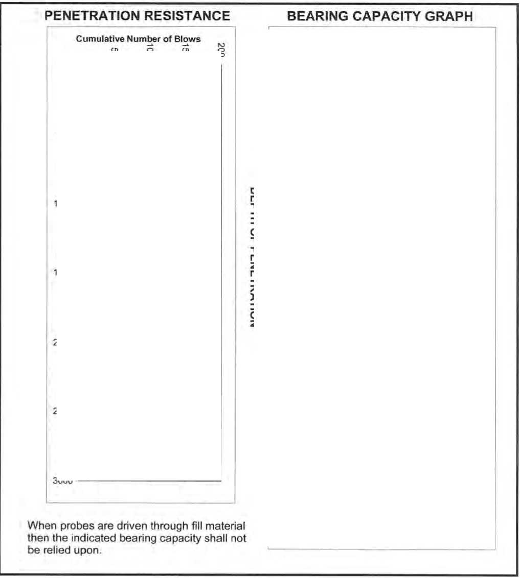
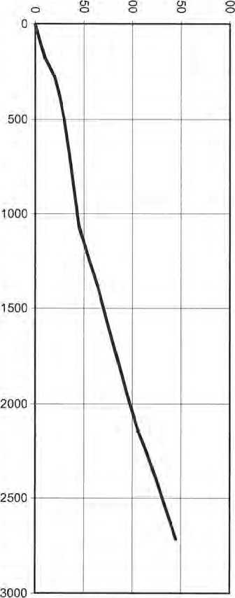
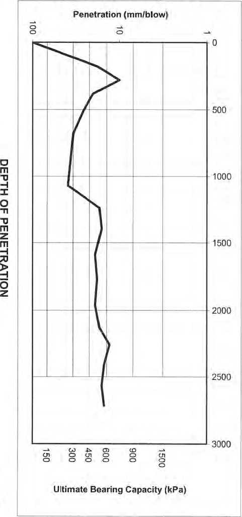
|
nr < Lu- E o E & o a x |
-J o CD s C/) |
z o £ or o P in Lu GO CM O |
REMARKS COLOUR, MOISTURE, GRADING. | |
|
HOLE 1 |
GROUND | |||
|
200 |
CL |
BROWN SANQ/CLAY OF MEDIUM PLASTICITY (MANY POCKS 2-2ūmmf | ||
|
400 | ||||
|
600 | ||||
|
800 | ||||
|
1000 | ||||
|
1200 | ||||
|
1400 | ||||
|
1600 | ||||
|
1800 | ||||
|
2000 | ||||
|
2200 | ||||
|
2400 | ||||
SpencerHo|n(es
engineers - surv^y^rs
TEST DATE:
28/01/22
HOLE LOCATION(S):
NOTES:
|
MAJOR DIVISIONS 0 |
I i 3 5 CM o |
TYPICAL NAMES | |
|
GRAVELS J ° (more than 1/2 of < |
’JGM |
Silty gravels, gravel-sand-silt mixtures | |
|
E E CO O —1 o O ° to A O *5 Id 2 o L? O - LlJ § (/) £ 81 |
coarse fraction ^ > 2 mm) |
iGC |
Clayey gravels, gravel-sond-clay mixtures |
|
• • • 4 |
sw |
Well graded sands or gravelly sands, little or no fines | |
|
SANDS (more than 1/2 of |
SP |
Poorly graded sands or gravelly sands, little or no fines. | |
|
coarse fraction < 2 mm) |
••SM |
Silty sands, sand-silt mixtures | |
|
f SC |
Clayey sands, sand-clay mixtures | ||
|
"e E CD co ° _1 o O v CO - Qi " 2 ° < X tr - O c o Ld 5 2 £ u_ o |
SILTS AND CLAYS W |
lCL |
Sandy clays, silty clays, lean clays |
|
( LL < 50 ) |
0L |
Organic silts and organic silty clays of low plasticity | |
|
MH |
Inorganic sifts, fine sandy or silty soils, elastic silts | ||
|
SILTS AND CLAYS % |
|ch |
Inorganic clays of high plasticity, fat clays | |
|
( LL > 50 ) | |||
|
1OH |
Organic clays of medium to high plasticity, organic silty clays, organic silts | ||
|
WS |
/W zw. | ||
|
HIGHLY ORGANIC SOILS ^ |
zxzv —- . s PT |
Peat and other highly organic soils | |
CLASSIFICATION CHART
( Unified Soil Classification System)
Spencer Holmes Ltd 57 Willis Street, Level 10 PO Box 588
Wellington New Zealand
Phone (04) 472-2261
Fax (04) 471-2372 email admin@spencerholmes.co.nz
SITE INVESTIGATION
910 HIGH ST
NAENAE
CAD file E200384-AU1 +
^ 28 JAN. 2022
SCALE
DRAWING NUMBER
E20-0384-AU1
REV
Spencer Holmes Ltd Directors: Mark Cooney, Jon Devine, Ian Leary, Philip McConchie, Hudson Moody
Associates: Jo Cushen, Vaughan England, David Gibson, Shayne McKenna, John McNaughton, Hayden Milburn, Thomas Smith
Consultant: Peter Smith, Hudson Moody
SpencerHolmes
engineers - surveyors - plann
STRUCTURAL SPECIFICATION
FOR
ADMIN BLOCK ALTERATIONS
AT
NAENAE COLLEGE 910 HIGH STREET AVALON LOWER HUTT
FOR
NAENAE COLLEGE BOARD OF TRUSTEES
Spencer Holmes Limited 57 Willis Street
PO Box 588
WELLINGTON
Phone (04) 472 2261
CONTENTS
1 PRELIMINARY & GENERAL
-
1.1 Referenced Documents
Throughout this specification, reference is made to various Ministry of Business, Innovation & Employment (MBIE) Acceptable Solutions and Verifications Methods for New Zealand Building Code Clauses used to establish compliance with the New Zealand Building Act.
Reference is also made to various Standards produced by Standards New Zealand (NZS, AS/NZS, NZS/AS), New Zealand Transportation Authority specifications (NZTA), Transit New Zealand specifications (TNZ) to overseas standards and to listed Acts, Regulations, and various industry codes of practice and practice guides. The latest edition (including amendments and provisional editions) at the date of this specification applies unless stated otherwise.
It is the responsibility of the Contractor to be familiar with the materials and expert in the techniques quoted in these publications.
Documents cited both directly and within other cited publications are deemed to form part of this specification. However, this specification takes precedence in the event of it being at variance with the cited documents, with the resolution of any variances being confirmed by the Contract administrator in writing and then notified to the Building Consent Authority for consent prior to any work proceeding.
-
1.2 Temporary Works
The Temporary Works consists of the preparation of programmes, methodology statements and “falsework” design that define the method and sequence in which the building or structure is to be built. In this context, falsework refers to all staging, temporary propping and bracing, scaffolding and access, that is, that there is at least one method and sequence that can be followed to construct the design. It includes shop drawings, shoring, cranage, site access and the like.
The contractor shall be responsible for providing all appropriate temporary works for the project to be undertaken and completed in a safe and secure manner.
Support and brace the existing structure during the cutting of new openings or the replacement of structural parts. Prevent debris from overloading any part of the structure. Do not remove supports until the new work is strong enough to support the existing structure. Ensure all work remains structurally stable and sound.
-
1.3 Ground Conditions
If a geotechnical report has been undertaken for the site this section is to be read in conjunction with the report, any discrepancies between the two documents should be brought to the attention of the engineer.
-
1.3.1 Bearing
The ultimate ground bearing capacity to be 300kPa minimum firm natural ground or certified fill under all foundations or as per the drawings and the engineer is to be informed of any discrepancies between the drawings and the ground conditions on site.
-
1.3.2 Excavation
The location of the neighbouring boundaries should be defined before excavation adjacent to a boundary commences, no excavation is to be undertaken across a boundary without the neighbours written consent. The extent of excavation should be true to the lines as shown on the drawings, do not over excavate.
No excavation is to be undertaken below a 45 degree plane of influence from an adjacent buildings foundation or retaining wall footings. The engineer must be informed of the situation and provide confirmation before any excavation can continue.
The maximum depth of cut or batter is to be no more than 2.5m in depth, any cuts deeper than this must be benched and approved in an excavation methodology report.
-
1.4 Wind Speed
Non-specific aspects of structural design complying with the requirements of NZS 3604 for a “Medium” wind speed zone.
-
1.5 Proprietary Products
All proprietary products are to meet the performance requirements of the manufacturer’s specification, and be installed strictly in accordance with the manufacturer’s requirements.
The engineer is to be informed and is to confirm the use of any propriety product that differs from that shown on the plans or specification.
-
1.6 Durability
-
1.6.1 B2 Acceptable Solution for Structural Timber
-
NZS 3602:2003 Chemical preservation of round and sawn timber
NZS 3604:2011 Timber framed buildings
NZS 3640 Part 1:2003 Timber and wood-based products for use in building
Timber treatment is to be selected in accordance with Table 1A of B2/AS1. The timber treatment is to be specified by the Architect and/or others.
-
1.6.2 B2 Acceptable Solution for Structural Concrete
NZS 3101 Part 1:2006 Concrete structures standards
Concrete covers have been selected in accordance with NZS 3101, Part 1, Section 3.
-
1.6.3 B2 Acceptable Solution for Structural Steel
SNZ TS 3404:2018 Durability requirements for steel structures and components
Steel protection has been specified in accordance with SNZ TS 3404 Table 6.
-
1.6.4 Exposure Zones
NZS 3604 = Exposure Zone C (Medium)
-
1.7 Construction Monitoring
The primary responsibility for completing the contract works in accordance with the requirements of the plans and specifications is the constructor's.
The involvement of the consultants during the construction phase is to ensure that;
-
• The design is being correctly interpreted,
-
• The construction techniques are appropriate and do not reduce the effectiveness of the design, and
-
• The work is completed generally in accordance with the plans and specifications.
This project requires verification of specific design aspects of the construction by a suitably qualified Chartered Professional Engineer in accordance with ACENZ/IPENZ level CM3, defined as;
Review, to an extent agreed with the client, random samples of important work procedures, materials of construction and components for compliance with the requirements of the plans and specifications and review important completed work prior to enclosure or on completion as appropriate. Be available to provide the constructor with technical interpretation of the plans and specifications.
-
1.7.1 Role of Spencer Holmes Limited
Spencer Holmes Limited have been engaged to undertake construction monitoring to Level CM3 in accordance with ACENZ Conditions of Engagement of the structural aspects which have been specifically designed.
-
1.7.2 Inspections
The following schedule of on-site inspections is required by Spencer Holmes Limited in order to meet the required level of Construction Monitoring specified, and to ensure the intent of the design is satisfied;
-
• Piles pre-pour
-
• Structural Steelwork
-
• Structural timberwork
It may also be appropriate to contact Spencer Holmes Limited on occasion in order to address contingent design issues during construction.
Contact Engineer: Joseph Bond
027 262 7144
Aspects of the timber framing and preline inspection for standard wall bracing within the scope of NZS 3604 is to be undertaken by an inspector from the territorial local authorities.
-
1.7.3 Producer Statements
In order to issue a Producer Statement PS4 Construction Review, Spencer Holmes Limited will require from the Contractor a Sixth Schedule Form of Producer Statement - Construction in accordance with NZS 3910 on completion of the structural works.
-
2 CONCRETE WORKS
-
2.1 Preliminary & General
-
Refer to the Preliminary and General Clauses of this Specification and to the General Conditions which are equally binding to all trades. This section of the Specification shall be read in conjunction with all other Sections.
-
2.2 Scope
This section includes manufacturing, supplying, forming, positioning and placing of all concrete joining, and all other work attached to or embedded in the concrete necessary for the completion of the structure as shown on the plans or specified herein.
-
2.3 Standards
Unless otherwise specified or otherwise shown on the drawings all reinforced concrete work shall be carried out in strict accordance with the provisions of the New Zealand Building Code, NZS 3109:1997 "Specification for Concrete Construction", and related standards.
-
2.4 Materials
All materials shall comply with the current relevant NZ Standard.
-
2.4.1 Cement
Cement shall comply with the requirements of NZS 3122. Unless otherwise specified cement shall be Type GP, General Purpose Portland cement or Type GB, General Purpose Blended Cement. The use of supplementary cementing materials is encouraged. The use of type HE (high early strength), LH (low heat) or SL (low drying shrinkage) cements require the approval of the Engineer.
Cement in storage shall be kept dry and on a platform at least 225 mm above the ground.
Cement which has become lumpy or partially set shall be condemned and removed from the works immediately. Cement shall be stored and handled as to be protected from moisture or any contamination.
The Engineer may at any time require tests or analysis to be carried out in accordance with the Standards. Any cement not approved shall be removed from the site or from the place of manufacture.
-
2.4.2 Aggregates
Aggregates and their grading shall comply with NZS 3121.
The source of the aggregates shall be approved prior to commencement of manufacture and neither the source of the aggregate nor the grading shall be changed during the course of the contract without approval.
When requested by the Engineer, the supplier shall submit the results of sieve analyses carried out by a laboratory qualified and equipped for such work.
The use of pumps for concrete placement shall not constitute an acceptable justification for reduction in aggregate size.
-
2.4.3 Water
Water shall comply with NZS 3121 and shall be free from significant amounts of deleterious impurities.
-
2.4.4 Additives
-
2.4.4.1 Air Entrainment
-
Where the manufacturer considers it desirable, an air entrainment agent may be added providing the use complies with the requirements of NZS 3109 are complied with.
The target air content shall never exceed the maximum target air content specified in NZS 3109.
Where a super plasticiser is used no air entrainment shall be adjusted for the air entraining effects of the super plasticiser.
-
2.4.4.2 Super plasticiser
Where specified, a super plasticiser of Daracem 100 (or similar approved) as manufactured by WR Grace shall be used at the rate recommended by the manufacturer sufficient to increase the slump from an initial of 50mm to 140mm.
-
2.4.4.3 Other Additives
No other additives shall be used without the approval of the Engineer.
Admixtures shall not contain calcium chloride, nor shall they adversely affect the reinforcement or any protective coating thereon.
Expansive admixture is not to be used in polystyrene block walls.
-
2.4.5 Alkali Silica Reaction
The alkali content in the cement shall not exceed 0.6% by weight and the total alkali content in the concrete shall not exceed 2.5 kg/m3. Where sand or aggregate is proposed that is potentially reactive as defined in CCANZ TR 03 Alkali Silica Reaction then the Engineer shall be notified and mitigation measures shall be submitted.
-
2.4.6 Reinforcement Steel
Reinforcing bars shall be either Grade 300E or Grade 500E complying with AS/NZS 4767, as designated on the drawings. (Bars designated with an "X", “H” or “RB” prefix shall be Grade 500E).
Grade 300E round mild steel rods complying with NZS 3402 shall be used for all stirrups, column ties and other reinforcement requiring tight hooks or tight bends, unless noted otherwise
Grade 300E and grade 500E MA deformed steel rods complying with AS/NZS 4671 shall be used for all other reinforcement as detailed.
All high strength reinforcing steel to be New Zealand manufactured micro alloy steel (denoted as MA).
Imported reinforcing steel will NOT be accepted without the specific written approval of the Engineer, and shall be demonstrated to be in accordance with AS/NZS 4671 and manufactured by the micro alloy process.
Welded wire mesh reinforcement shall be ductile meshing conforming to the requirements of AS/NZS 4671 and shall be ductility class E, have a minimum yield stress of 500 MPa, maximum of 600 MPa and a uniform elongation of over 10%.
All terminal ends of reinforcing bars shall be hooked. Intersecting walls, beams and foundations shall contain return longitudinal reinforcement, as detailed for the intersecting members, unless shown otherwise on the drawings.
Unless detailed otherwise all bars shall be assumed to be continuous, with lap lengths of 40 and 60 bar diameters for Grades 300E and 500E respectively.
All hooks shall be standard hooks in accordance with NZS 3109.
At the time concrete is placed, steel reinforcement shall be clean and free from all loose scale, rust, dried mortar, oil, paint, retardant or other coating which may prevent perfect bond.
Reinforcement appreciably reduced in section by corrosion or local pitting shall be rejected.
-
2.4.6.1 Epoxy Fixed Dowels and Starter Bars
Epoxy grout shall be Hilti HIT-HY RE500, Ramset Epcon C8, or an approved equivalent system, and shall be used strictly in accordance with the manufacturer's instructions.
All epoxy products to be mixed, stored and placed strictly in accordance with manufacturer’s instructions.
Epoxy shall only be placed at temperature and moisture/humidity levels that meet the manufacturer’s guidelines.
Concrete shall be at least 7 days old before epoxy grouting work may proceed. If a diamond head drill is used the holes must be pre-roughened to the Engineer's approval.
Holes for grouted in bars shall be typically be a minimum of 6mm larger than the nominal diameter of the bars to be grouted (or as per the manufacturer's instructions) and shall be drilled, generally at 20 degrees to the horizontal.
The holes shall be blown out with compressed air to remove all spallings and drill dust, and shall be thoroughly dry prior to grouting.
The steel dowels shall be degreased and dipped in epoxy and sufficient epoxy injected into the hole to fill the cavity on placement of the steel dowel. The steel dowel shall then be placed into the hole and forced back into the hole until epoxy is ejected around the perimeter of the dowel
-
2.4.7 Vapour Barrier / Moisture-proofing
Unless otherwise specified on the drawings, or by the architect, vapour barrier / moisture-proofing shall be 0.25mm Polythene or similar approved underlay, taped at all joints and penetrations with Danco Insultape 100 (72mm width), and laid over 25mm sand blinding.
Protect vertically applied membrane against puncturing from backfill operations with 4.75mm minimum thickness fibre cement board.
-
2.5 Concrete Mix Designs
-
2.5.1 Schedule of Concrete Mixes
Concrete mixes shall be as follows:
ID
Location
Strength* (MPa)
Type
Max Aggregate Size (mm)
A
Site Concrete
17.5
Normal
19
B
Reinforced Piles
20
Normal
19
* Specified cylinder compressive strength at 28 days.
-
-
2.6 Manufacture of Concrete
-
2.6.1 General
-
All concrete shall be as per the mix designs given at the end of this Section.
The Contractor shall notify the Engineer in writing before commencing the works whether he intends to use ready-mixed or site-mixed concrete. Site mixing of concrete will not be permitted where ready-mixed concrete is available unless approved by the Engineer. Ready-mixed concrete shall comply with the requirements of NZS 3104, and shall be supplied by an approved supplier from a plant approved by the New Zealand Ready Mixed Concrete Association for the manufacture of the nominated grade of concrete. This approval is to be sought prior to the commencement of the Works.
Manufacture shall comply with the requirements of NZS 3104 and all details of the proposed concrete supply as required by NZS 3109 clause 6.9 and 6.10 shall be submitted to the Engineer for approval prior to commencement of supply.
-
2.6.2 Manufacturer's Control Testing
The Contractor shall allow for all costs incurred by the manufacturer in order to carry out quality control testing as required by NZS 3104. Results shall be forwarded to the Engineer within 7 days of testing.
-
2.7 Inspection
The Engineer shall be advised at least 24 hours before any concrete is to be placed so that he may inspect the formwork, reinforcement, foundations, construction joints and discuss proposed placing methods before placing commences.
-
2.8 Delivery of Concrete to Site
Concrete shall be delivered from the batching plant to the site in accordance with NZS 3104. Concrete shall be transported without loss of mortar or segregation. Delivery dockets shall show the job, date and time of loading the mixer drums, grade, specified strength and slump.
The time between adding the ingredients to the mixer and discharging at the site shall in no case exceed 90 minutes, or 300 revolutions, whichever comes first or such shorter time as directed by the Engineer.
The addition of water to the mix after dispatch from the ready mix plant is strictly forbidden.
Copies of all delivery dockets shall be collected by the foreman.
-
2.9 Handling & Placing
-
2.9.1 General
-
All concrete shall be handled and placed in cleaned and prepared formwork in accordance with NZ Standards, with care being taken to avoid segregation and to minimise the time between manufacture and placement.
The method of placing concrete shall be approved by the Engineer prior to placing concrete, but such approval will not absolve the Contractor from providing dense homogeneous concrete.
Work on the section to be poured shall be complete in all respects before pouring starts.
No concrete shall be placed until the engineer has approved the foundations, reinforcing steel, formwork and construction joint preparation.
Concrete shall be transported, handled and placed in a manner which will avoid segregation and shall be placed before initial set occurs. Where reverberations of any layer fails to cause the concrete to become plastic, no fresh concrete shall be placed over it and the surface of the layer shall be treated as a construction joint. No concrete shall be placed over any layer in which initial set has already taken place.
Dropping of concrete through a free fall greater than 2 metres shall not be permitted unless otherwise approved. For tall vertical elements the maximum fall of concrete shall be limited to 1.5m/100mm of member thickness.
As far as possible the placing of concrete shall be controlled to ensure that any free fall is entirely clear of reinforcement.
Concrete shall be placed directly in corners, at ends and at 1.5m intervals along the formwork. The depth of each layer shall not exceed 500mm and it shall be well worked into the preceding layer.
The depositing of a large quantity of concrete at any point with the intention of moving it along the forms will not be permitted.
The use of troughs, chutes and pipes to aid in depositing concrete to its final position shall be permitted provided that they are kept clean and free of any coating of hardened concrete.
The use of water to facilitate the movement of concrete along the troughs, chutes or pipes will not be permitted.
-
2.9.2 Unfavourable Conditions
Concrete shall not be placed on frozen ground, nor shall concrete be placed in unfavourable conditions which may be detrimental to the quality and finish of the concrete in the structure, unless adequate precautions are being taken. Unfavourable conditions shall be deemed to include low temperatures (below 5 degrees with temperature descending or below 2 degrees with temperature ascending), excessively hot dry conditions, excessively wet conditions or any conditions making it impracticable to work or finish concrete adequately. Refer to CCANZ TM 35 New Zealand Guide to Concrete Construction Section 12.1.6 Plastic Cracking for further recommendations.
When the pouring of concrete is interrupted by rain, the area shall be covered immediately and the pour shall then be terminated at properly formed construction joints in positions approved by the Engineer.
Where the temperature may drop overnight by over 13° insulation shall be used to protect the concrete from the temperature drop. Further recommendations are found in CCANZ TR10 Specifying Concrete for Performance Section 6.3.2.
-
2.9.3 Construction Joints
All construction joints are to be prepared to an exposed aggregate finish of 5mm minimum roughness between pours i.e Rugasol and waterblasting surface. This is a requirement for the structural walls.
Where new concrete is to be bonded to old concrete the surface of the old concrete shall be prepared by chipping back to expose fresh aggregate.
The concrete placing shall be carried out continuously between construction joints and in such a manner that a plastic concrete face is maintained. Where the location of construction joints are shown on the drawings, they shall neither be relocated nor eliminated without the approval of the Engineer. Where no construction joints are shown on the Contract Drawings and such are required, their location shall be to the approval of the Engineer.
-
2.9.4 Vibration
Unless specifically instructed otherwise, all concrete shall be vibrated to produce a dense uniform mass with at least two approved high frequency immersion vibrators (not less than 133 Hz) operated by experienced workmen.
The vibration shall be sufficiently intense to cause the concrete to settle rapidly into place and to positively affect the concrete over a radius of at least 500mm. The vibrator shall be uniformly inserted, not further apart than the vibration is visibly effective and sufficiently close to the forms to effectively vibrate the concrete at the formed surface.
Vibration shall be such that expulsion of entrapped air and settlement of the concrete is visibly evident over all areas of the surface and shall continue until this action ceases and until coarse aggregate at the surface is embedded. Vibration shall not be prolonged beyond the time at which this condition is reached and care is to be taken to avoid vibration of reinforcing steel or formwork and to withdraw the spud slowly.
-
2.10 Curing
-
2.10.1 General
-
Freshly cast concrete surfaces shall be protected from premature drying and excessively hot or cold temperatures or damage from rain. Curing shall be commenced as soon as the exposed surface has hardened sufficiently but not later than two hours after finishing.
All concrete surfaces shall be cured for a minimum of 14 days. Curing may consist of maintaining the concrete surface wet by periodic hosing or a continuous fine water spray for 14 days or by periodic hosing for the first 7 days followed by the use of a sprayed membrane for a further 7 days.
Polythene or hessian may be used to reduce water loss. All plastic sheeting must be fully lapped at joints and sealed at the edges.
Where form work is removed from vertical surfaces within the specified curing period, the exposed concrete surface shall be fully cured.
-
2.11 Surface Finish
-
2.11.1 General
-
Surface finishes shall be as set out in the Schedule of Surface Finishes at the end of this section of the specification.
Surface finishes shall comply with the requirements of NZS 3114 for the class of surface finish nominated.
All surfaces shall be finished true to line and level as shown on the Drawings and shall be free of bony or porous areas and excessive depressions or projections. Horizontal surfaces shall be finished with a wood or steel float as required to achieve the tolerances specified in NZS 3109.
The Contractor shall be responsible for determining the method of producing the specified finish and for ensuring that the execution of the work at all times is carried out and supervised by personnel skilled in the production of the class of finish specified.
-
2.11.2 Formed Surfaces
Surface tolerances, colour variation and physical irregularities shall comply with the requirements of NZS 3114 for the class of finish specified in the schedule of surface finishes.
Bolt holes shall be filled in accordance with the treatment specified.
When the surface finish does not comply with the requirements of the specified surface finish, and minor surface defects exist, the surface dressing treatment for minor repairs shall be carried out as specified below.
-
2.11.3 Unformed Surfaces
Surface tolerance, colour variation and physical irregularities comply with the requirements of NZS 3114 for the class to finish specified in the schedule of surface of surface finishes.
Floor surfaces shall have no abrupt deviations, and gradual deviations shall not vary by more than 3mm from a 3 metre straight edge placed anywhere on the surface, and such maximum variation shall extend over a minimum distance of 1 metre.
-
2.11.4 Schedule of Surface Finishes
Location
Formwork
Surface Finishes
Fillets
Stripping Agent
All floor slabs
-
F4 / U3 X
-
-
Top surface of foundations not exposed on completion
-
F1 / U2
-
-
Top surface of foundations exposed on completion, and all other surfaces
-
F4 / U3
-
-
-
2.11.5 Special Requirements for U3 X Finish
Where a “U3 X” surface finish has been specified, the floor shall be compacted and floated with "Kelly" machines fitted with discs to provide a smooth level uniform and dense hard wearing surface.
At least two machines shall be available at the time of finishing.
Along walls and in other inaccessible positions, finish by hand steel trowelling.
Hand finish edges of slab to provide a dense hard wearing surface.
Do not commence finishing until the moisture film has disappeared from the screeded surface and the concrete surface has hardened sufficiently to prevent an excess of fine material from being worked to the surface.
-
2.12 Surface Dressing
-
2.12.1 Minor Defects
-
Where a portion of an exposed surface requires treatment, the whole of the exposed surface of the defective face of the member shall be treated.
The surface shall be thoroughly wetted and shall be painted with a thin grout of 1:1.5 cement: fine sand worked in by vigorous rubbing with cork or wood floats and finally rubbed smooth with burlap.
After drying remove any surplus sand with Carborundum stones.
The surface on completion shall be dense, smooth, free from defects and match the parent surface in colour and texture.
Abrupt deviations shall be ground to a 1 in 50 height to length and fins and projection shall be ground flush.
Surface dressing shall be cured for 7 days.
-
2.13 Repair of Major Defects
The Engineer shall be notified of any major surface defects. When the Engineer permits a repair to be attempted the repair shall be carried out as soon as practicable after stripping. Acceptance of the entire concrete pour incorporating the repair will be dependent upon the adequacy of the repair. Where a substantial defect occurs, the presence of which would jeopardise the structural integrity of the building, the entire concrete pour containing the repair shall be removed and replaced at the Contractors expense.
-
2.14 Protection
Protect all new concrete work and ensure that no heavy loads are placed on or moved over the finished concrete until 28 days old.
-
3 STRUCTURAL STEELWORK
-
3.1 Preliminary & General
-
Refer to the Preliminary and General Clauses of this Specification and to the General Conditions which are equally binding to all trades. This section of the Specification shall be read in conjunction with all other Sections.
-
3.2 Scope
The work to be done under this Section comprises the supply of all labour, materials and plant for the fabrication and erection of all structural steelwork and miscellaneous metalwork shown or implied on the drawings or in the specification.
-
3.3 Standards
Materials and workmanship shall confirm to the current requirements of the following Codes and Standards except where modified by this Specification;
NZS 3404
AS/NZS 1554
AS/NZS 2312
SNZ TS 3404
Steel Structures Standard
Welding of Steel Structures
Guide to the protection of structural steel against atmospheric corrosion by the use of protective coatings
Durability requirements for steel structures and components
-
3.4 Materials
-
3.4.1 Steel
-
Hot-rolled structural steel shall be G300 in accordance with AS 3679.1.
Hollow structural steel sections shall be C350 in accordance with AS 1163.
Steel plate shall be G250 or G300 in accordance with AS 3679.1.
-
3.4.1.1 Supply And Substitution
The Contractor shall not substitute specified structural steel sections without the approval of the Engineer. Generally members shall be fabricated using single length sections. Members fabricated using short length sections shall not be made without the approval of the Engineer.
-
3.4.1.2 Samples And Tests
The Contractor shall allow for the taking of all samples and the supply of all material certificates required by this Specification.
The Contractor shall allow for carrying out of all tests specified in this Specification.
If, in the opinion of the Engineer, the material or workmanship is defective, he may require the Contractor to carry out additional tests. If these tests show the material or workmanship to be unsatisfactory, all costs associated with testing and making good shall be borne by the Contractor. Should the tests prove satisfactory, such costs shall be borne by the Principal.
-
3.4.2 Bolts
All nuts and bolts shall be 150 metric coarse threads, hexagon Grade 4.6 (AS1111 and AS 1112 respectively).
All bolt, nuts and washers shall be hot dipped galvanised.
All bolts shall be fitted with appropriate washers. At least one washer shall be placed under the bolt head or nut whichever is to be rotated.
Tapered washers shall be used where the part under the bolt head or nut is not perpendicular to the centreline of the bolt.
Nuts or bolts subject to severe vibration and vertical bolts in tension shall be locked in position using an approved method.
Unless noted otherwise, holes shall be 2mm larger than the nominal bolt diameter. Where slotted or oversize holes are permitted in the drawings they shall comply with AS 1511.
No part of the threaded portion of the bolt of a bearing bolt shall be within the thickness of the parts to be bolted together.
Threaded ends of bearing bolts projecting greater than 10mm from the end of the nut, if visible from the completed structure, shall be cut off flush with the end of the nut, except as otherwise specified.
Suitably store bolts to protect from corrosion.
Retain coating of oil to bolts.
-
3.5 Workmanship
-
3.5.1 General
-
All workmanship on or off-site shall be in accordance with NZS 3404. All work shall be carried out by skilled and appropriately qualified tradesmen.
Where portions of the work are exposed to view and form part of the architectural treatment, attention shall be given to the finish. Shearing, flame cutting and chipping shall be done carefully and accurately. Sharp corners and edges, and edges that are marred, cut or roughened in handling or erection shall be faired by grinding or other approved means.
Flame cutting of holes for bolts or rivets (including enlargement of drilled holes) will not be permitted. Remove all burrs and other defects from all holes.
Where noted on the Engineer's drawings, steelwork exposed to view shall have welds ground smooth.
-
3.5.2 Responsibility
The Contractor shall be wholly responsible for carrying out all the structural steelwork in accordance with the requirements of this Specification and the associated Contract Documents.
Should the Contractor become aware of any conflict of components, signs of distress or excessive deflection in any member at any stage during detailing, fabrication or erection of the steelwork, he shall immediately notify the Engineer, and confirm such notice in writing as soon as is practicable.
-
3.5.3 Drawings
The drawings indicate the general arrangement and dimensions of the steelwork and have been made to scale. Where dimensions have not been given, scaled dimensions shall not be used.
Where steelwork is being placed onto or connecting with existing construction, the Contractor shall check and verify all dimensions and levels on site before commencing fabrication of any new steel. Any discrepancy found between the drawings and the site dimensions shall be referred immediately to the Engineer who shall direct any amendments as necessary.
The structural drawings and the architectural drawings are complementary and the Contractor shall consult the latter for materials, details and dimensions not shown on the former. If any discrepancies are found within the drawings refer to the Engineer for instructions before proceeding.
-
3.5.4 Construction Procedure
The Contractor shall be responsible for his construction procedure and must ensure that no part of the structure is overstressed as a result of construction loads. If required, the Contractor shall provide calculations for examination to the Engineer which show that the structure is adequate to support the proposed construction loads.
-
3.5.5 Miscellaneous Connections and Attachments
Where end cleats, brackets and other connections are not specifically detailed on the Engineer's drawings, they shall be of a type and proportion to suit the location and reaction shown thereon.
The Contractor shall allow for any drilling and cleats indicated on the Engineer's drawings, and those necessary to support and connect finishes and fixings of other trades.
-
3.6 Fabrication
-
3.6.1 Clearances and Tolerances
-
The structural steelworker shall be fully responsible for checking on-site all dimensions relating to the setting out of all portal frames, sockets, angles, plates, bolts, dowels, etc, before commencing fabrication. Any discrepancies are to be reported to the Engineer, and work is to be put on hold until further instructions are given.
The Engineer shall be notified well in advance of commencement of work in the shop in order that inspections of materials and workmanship may be made.
The end clearances shown on the Engineer's drawings shall not be exceeded; where these are not shown the Contractor shall ascertain the clearances used in the design of the connections.
Structural members consisting primarily of a single rolled section shall, after fabrication, unless otherwise specified, conform to the tolerances prescribed in NZS 3404. Built up structural members, unless otherwise specified, shall conform to the tolerances specified in clause 15.3 of NZS 3404.
Completed members shall be free from twists and bends, within a tolerance of 1 in 1000 from a flat plane in any direction, and not more than 6mm overall. Open joints, sharp kinks and bends shall be cause of rejection. All parts to be joined shall fit accurately before welding. Re-entrant cuts shall be filleted to a radius of not less than 10mm.
Tolerances in straightness and length shall conform with clause 15.3.3, 15.3.5 or 15.3.6 of NZS 3404 as appropriate. These tolerances shall not result in a cumulative error over the whole or any part of the structure.
Sheetmetal and plate bending shall be in accordance with AS/NZS 3678-2011 Table C1. Alternatively join with complete penetration butt welds.
-
3.7 Welding
-
3.7.1 General
-
All welding shall conform to the requirements of AS/NZS 1554.1: Structural Steel Welding. All welding shall be category SP Structural Purpose unless noted otherwise.
Preparatory work, procedure and sequence of welding shall be such as to obviate distortion and minimise shrinkage stresses. Fully prepare and clean off all fusion faces and surrounding surfaces. Work is to be positioned for flat welding wherever possible.
Maintain a 5mm gap between all parts to be butt welded together by use of soft wire cushions. All butt welds shall be brought up proud of the parent metal.
The Contractor shall arrange for all welders employed on the work to be tested by welding inspectors nominated by the Engineer. The testing shall be in accordance with the requirements of NZS 2980: Qualification of Welders for Fusion Welding of Steels, and the Contractor shall be responsible for the payment of all costs in respect of the tests.
Welders shall only be employed on the types of weld for which they have satisfactorily completed tests.
Site welding shall not be undertaken without approval.
-
3.7.2 Weld Symbols
Symbols shown on the drawings are in accordance with AS 1101.3-2005 Graphical Symbols for General Engineering - Welding and Non-Destructive Examination.
-
3.7.3 Weld Classification Schedule
The extent non-destructive examination of welds shall be in accordance with NZS 3404 Table 34 and AS/NZS 1554 as follows;
|
Welding Classification Schedule | |||||||
|
Location |
Frame Structural Ductility Category |
Weld Failure Consequence (redundancy) |
Seismic Demand |
Fatigue |
Non-Destructive Testing | ||
|
CPW |
k-area |
Fillet Weld | |||||
|
All |
4 Elastic µ=1 |
A - Major |
Low |
NA |
UT 10% including 2 of the first 10 |
MT 10% |
NA |
-
3.7.4 Testing
Weld testing shall be in accordance NZS 3404.1 2009 Steel Structures Standard Table 34 and the above Welding Requirement Schedule.
Before any welding is commenced, the Engineer shall be advised so that an inspection of the prepared surfaces can be made.
The testing of welds will be carried out by a specialist organisation and may include ultrasonic testing or radiography or such other methods of testing or such other methods to testing considered appropriate by the welding inspector.
The Contractor shall comply with all reasonable demands of the welding inspector to cut out weld in search of defects and shall supply the plant necessary for the purpose. The cost of testing welds shown to be defective, and the repair or making good thereof, shall be bourn by the Contractor.
-
3.7.5 Weld Defects
If, in the opinion of the Engineer, the total amount of repair in any one welded seam is excessive, the whole of the seam shall be cut out and rewelded.
Defects shall be cut out by Arc/Air and the gouging heat shall be the smallest necessary to satisfactorily achieve the cut.
The inspector shall examine all seams from which defects have been cut out and his approval obtained before rewelding is commenced. Rewelding shall be executed in a manner and by practices acceptable under this specification. Where practicable, the rewelding shall be by the same process as used in the original welding.
Preheating shall be used for all weld repairs.
The cost of all testing and repairs to all defects shall be borne by the Contractor.
-
3.8 Surface Treatment
Surface treatment shall be in accordance with SNZ TS 3404 Durability requirements for steel structures and components Surface treatment shall constitute complete systems of surface preparation and protective coatings.
|
3.8.1 Schedule of Surface Treatments | ||||||||||||||||||||||||||||||
| ||||||||||||||||||||||||||||||
|
Unless noted otherwise on the drawings all steelwork permanently exposed to external atmospheric conditions associated with decks and landscaping structures shall be hot dipped galvanised. | ||||||||||||||||||||||||||||||
-
3.8.2 Hot-Dip Galvanising
All articles to be galvanised shall be handled in such a manner as to avoid any mechanical damage and to minimise distortion.
Design features that may lead to difficulties during galvanising should be pointed out prior to dipping.
Galvanising parameters such as galvanising temperature, time of immersion and withdrawal speed shall be employed to suit the requirements of the article.
The composition of the zinc in the galvanising bath shall not be less that 98.0% zinc.
-
3.8.2.1 Surface Finish
The galvanised coating shall be continuous, adherent, as smooth and evenly distributed as possible, and free from any defect that is detrimental to the stated end use of the coated article. On silicon killed steels, the coating may be dull grey provided the coating is sound and continuous.
The integrity of the coating shall be determined by visual inspection and coating thickness measurements.
Where slip factors are required to enable high strength friction grip bolting, where shown , these shall be obtained after galvanising by suitable mechanical treatment of the faying surfaces.
Where a paint finish is to be applied to the galvanised coating, this should be advised at the time of order and all spikes shall be removed and all edges shall be free from lumps and runs.
-
3.8.2.2 Adhesion
The galvanised coating shall be sufficiently adherent to withstand normal handling during transport and erection.
-
3.8.2.3 Repair of Damaged Areas
Contractor is to inform engineer of damaged surfaces or welded areas before installation. Engineer is to inspect and advise contractor of repair requirements.
Damaged surfaces or welded areas shall be made good with Resene Amercoat 68A Zinc EPOXY Primer or equivalent applied strictly in accordance with the manufacturer's requirements.
-
3.8.2.4 Maintenance
The maintenance schedule for the galvanised steelwork that is exposed and permanently fixed is to be as per the methodology stated in Section 10 “Maintenance of Protective Coating Systems” from AS/NZS 2312: 1994 “Guide to the protection of iron and steel against exterior atmospheric corrosion” or any later revision.
The criterion for assessing when to paint the steelwork is 5% of the surface in any particular area is showing signs of rusting. The preparation and repainting system to be applied should be in accordance with the standard, and decided using the appropriate paint systems of the time.
|
Exterior steelwork shall be maintained as per the Schedule of Maintenance Items. | ||||||||||||||||
| ||||||||||||||||
-
3.8.3 Steel to Concrete Interfaces
Steel to concrete interfaces shall be in accordance with the New Zealand Steelwork Corrosion and Coatings Guide Section 12.16. Non conductive paint layers shall be placed at the interface region with mastic sealant beads. The mastic sealant bead shall be Sika AT-Façade.
-
3.8.4 Steel to Timber Interfaces
In some situations, such as a timber slat deck, steel-supporting beams support timber treated with copperbased treatment chemicals, which will be damp in use and therefore more corrosive to the steel.
In these situations, the steel should:
-
• be hot-dip galvanised after manufacture – all cleats and the like are attached before the member is galvanised
-
• have a specialist anti-corrosive coating system applied to the galvanised steel
-
• have an isolating layer, such as a DPC, between the steel and the timber when in close contact
-
• be fixed to the timber with 304 stainless steel bolts and washers
-
• have the bolts sleeved where they pass through the timber
-
• be checked annually for any deterioration.
-
3.9 Transportation and Erection
All transport and erection of fabricated sections shall be under the control of a competent foreman.
When transporting steelwork from place of fabrication to site for erection it shall be loaded, stored and unloaded in such a manner as to obviate straining of any parts.
The Contractor shall provide proper plant and all fuel, staging, tools and temporary fixings required for the safe proper and complete erection of structural steelwork.
Erect steelwork true to line and level without distortion or strain, in accordance with NZS 3404.
Remove all erection fittings and make good.
No holes shall be made in the flanges of any framing member for erection or for any other purpose unless specified.
Stability shall be ensured at all stages of construction with due allowance for wind and earthquake induced loads.
Dry packing under baseplates shall be undertaken using Conbextra or similar approved non-shrink grout, mixed to a consistency suitable for the nature of the application.
All bolts and fasteners shall be fitted with appropriate washers and shall be thoroughly tightened (to torque settings where recommended by manufacturers). Protruding ends of bolts shall be centre-punched against nuts to prevent loosening.
-
3.10 Bolting
Bolting procedures are identified in the following manner:
Bolting
Procedure
Strength Grade
Standard
Method Installation
Notes
AS 1111
Snug tightened to AS 1511
4.6
AS/NZS 1252
Snug tightened to AS 1511
-
3.10.1 Chemical Bolt Anchoring
-
Chemical bolt anchoring systems shall be as per specified on the drawings, typically shown as;
-
• Hilti HIT-RE 500 for anchoring into concrete.
Alternative products must be submitted to the engineer for approval.
Chemically anchored bolt fixings shall be installed in accordance with product specifications.
Proof testing of sample installations throughout the structure shall be completed in accordance with product specifications and in locations specified by the engineer.
Acceptance of proof testing results as meeting the requirements of the design loads is at the discretion of the engineer.
-
3.11 Site Welding
Site welding shall be carried out fully in accordance with previously stated requirements for welding.
-
3.12 Site Cutting And Drilling
During erection, steel members shall not be cut, burnt, welded or drilled in a manner not in accordance with the Engineering Drawings or Workshop Details.
Drifting may only be used to bring member into position and no enlargement of holes or distortion of connection components shall be permitted.
The Contractor shall adopt an erection procedure such that all members can be erected in position without distortion.
-
3.13 Bedding And Grouting
Where steelwork is supported by concrete, masonry or like material, it shall be set up on packing or wedges to facilitate alignment and permit subsequent grouting. Such packs, if permanent, shall be either of solid steel or grout of similar strength to the permanent grout. All other packs shall be removed before completion of grouting.
The grouting of base plates and other steelwork, where noted on the drawings, shall be carried out using an approved proprietary, flowable,non-shrink grout in accordance with the manufacturer's recommendations. Provided the necessary holes and header tubes to ensure the complete filling of the grout spaces.
On completion the stripped edges of the finished work shall be tidied and all grout splashes removed from the steelwork.
Unless shown otherwise all edges shall be finished to give a 45 deg. slope from the underside of the base plate.
-
4 STRUCTURAL TIMBERWORK
-
4.1 Preliminary & General
-
Refer to the Preliminary and General Clauses of this Specification and to the General Conditions which are equally binding to all trades. This section of the Specification shall be read in conjunction with all other Sections.
-
4.2 Scope
This section includes the manufacture, supply, erection and fixing of all structural timbers. Work covered by this section includes:
-
• Any work which would customarily involve the carpenter whether or not referred to in this specification or shown on the drawings necessary for the proper completion and maintenance of the works.
-
4.3 Standards
-
4.3.1 Materials
-
Materials and workmanship shall confirm to the current requirements of the following Codes and Standards except where modified by this Specification.
Timber and wood based products shall comply with NZS 3602. Timber shall be graded to comply with NZS 3631, “Classification and Grading of NZ Timbers New Zealand Timber Grading Rules”. All timbers shall be the best of its specific kind.
|
The following NZ Standards, including all related amendments, and other statutory references apply to | ||||||||||||||||||||||||||||||||
| ||||||||||||||||||||||||||||||||
All general framing, lintels, floor joists, beams and trusses to be a minimum of SG8 (Stress Graded) to the requirements of NZS 3622 “Verification of Timber Properties”.
Timber shall be dried to the specified moisture content according to recognised principals of air drying, by forced air drying or by kiln drying complying with NZS 3602 and AS/NZS 4787.
Framing timbers shall not exceed 24% moisture content at the time of enclosure. Unless otherwise specified, variation in moisture content shall not exceed the range specified in Clause 9.1205 of NZS 3602.
-
4.4 Materials
-
4.4.1 General
-
All general framing, lintels, floor joists, beams and trusses to be a minimum of SG8 (Stress Graded) to the requirements of NZS 3622:2004 “Verification of Timber Properties”.
Timber shall be dried to the specified moisture content according to recognised principals of air drying, by forced air drying or by kiln drying complying with NZS 3602 and AS/NZS 4787.
Framing timbers shall not exceed 24% moisture content at the time of enclosure. Unless otherwise specified, variation in moisture content shall not exceed the range specified in Clause 9.1205 of NZS 3602.
-
4.4.2 Plywood
Plywood shall meet the requirements of AS/NZS 2269. The properties shall be, unless specified otherwise on the drawings, as follows:
-
• Species shall be Radiata Pine.
-
• Surface grade either CD or D.
-
• Strength grade F8.
-
• Treated to H3.2 CCA.
The manufacturer shall be accredited by the Engineered Wood Products Association of Australasia (EWPAA).
Plywood ply arrangements shall be:
|
Thickness |
Number of Plies |
Identification Code |
|
7mm |
3 |
7-24-3 |
|
9mm |
3 |
9-30-3 |
|
12mm |
5 |
12-24-5 |
|
15mm |
5 |
15-30-5 |
|
17mm |
7 |
17-24-7 |
|
21mm |
7 |
21-30-7 |
|
25mm |
9 |
25-30-9 |
-
4.4.3 Laminated Veneer Lumber
Laminated Veneer Lumber shall meet the requirements of AS/NZS 4357. The properties shall be, unless specified otherwise on the drawings, as follows:
-
• Species shall be Radiata Pine.
-
• Strength grade shall be as per the nominated brand. When not given elsewhere the stress grade shall be F11.
-
• Treatment shall be H3.1 unless specifically nominated as untreated.
The manufacturer shall be accredited by the Engineered Wood Products Association of Australasia (EWPAA).
-
4.4.4 Glue Laminated Timber
Glued Laminated Timber shall meet the requirements of AS/NZS 1328. The properties shall be, unless specified otherwise on the drawings, as follows:
-
• Species shall be Radiata Pine.
-
• Adhesive types shall be as per AS/NZS 1328.1:1998 Table A1.
-
• Service class as per its location of either interior, exterior but protector or exterior.
-
• Appearance grade A.
-
• Minimum strength grade GL10.
-
4.5 Treatment
Timber shall be treated in accordance with the current requirements of the hazard specifications of NZS 3640. Treatments are to be in accordance with the requirements of NZS 3602: 2003 and the MBIE Acceptable Solutions and Verifications Methods for New Zealand Building Code Clause B2 Durability Acceptable Solution B2/AS1.
All timber shall be branded in accordance with the requirements of the Timber Preservation Council.
Timber supplied that is inappropriately treated and or incorrectly branded shall be removed and replaced with timbers that comply with the specification.
All cut surfaces of timber members treated to TPC specification H3 to H6 shall be protected by a liberal brush application of:
Concentrated tanalith solution, or Copper napthenate.
-
4.6 Workmanship
Shall be in accordance with best trade practice, and this shall be deemed to include those methods of practise and processes contained in current syllabuses for the New Zealand Trade Certificates in Carpentry, Joinery and Timber Machining National Certificate in Carpentry and National Certificate in Joinery.
All framing shall be in accordance with NZS 3604 “Timber Timber-Framed Buildings”. The best workmanship shall be employed in thoroughly securing and framing together, spiking and bolting down as the various circumstances require. Only skew nailing will be permitted in the framing. Punch all nails in exposed joinery and work to be painted. All nails and spikes shall be of gauge and length suitable for the particular work. Nails shall enter the second timber at least one half their length before punching.
Remove all arises, rough patches, hammer-marks, and other surface defects before painting is begun.
Checking and cutting away of timbers shall be avoided whenever possible, and shall be limited to such dimensions that will not prejudice the purpose for which the timber is used. No studs shall be cut across the grain to straighten them.
Wherever possible, beams and joists shall be holed at mid-height, and the hole size shall be limited to one fifth of the depth of the member. Holing within 600mm of the ends of members shall be avoided.
-
4.7 Gauging and Thickness
All framing timbers shall be thicknessed to produce regular plain surfaces. All exposed timbers are to be gauged.
-
4.8 Protection
-
4.8.1 Moisture Protection
-
All timber and wood based products shall be protected from moisture pick up during storage and erection. Members specified as “dry”, installed in a structure must be sealed or remain wrapped until the roof is installed.
All timber and timber products shall be stacked on well-aligned bearers, kept well clear of the ground or floor slabs, and covered for protection from sun and rain.
Any timber that at the time of installation has degraded beyond the specified limits shall be rejected.
-
4.8.2 Physical Protection
All timber and wood based products shall be adequately protected against physical damage during the currency of the contract.
Any physical damage to timber and wood based products shall be cause for rejection and replacement.
Large timber members should be handled with web slings. Cable or chain slings, fork lifts and tipping trucks my easily damage the timber and should be used with care.
Wherever deep and slender glue laminated sections are to be lifted when lying flat, guidance from the Engineer must be sought as to the number and location of lifting points.
-
4.9 Fixings and Fastenings
-
4.9.1 General
-
All fixings and fastenings shall be to the minimum standard required in accordance with NZS 3604 for the applicable wind zone.
-
4.9.2 Durability
The protection required for steel fixings and fastening excluding nails and screws shall be in accordance with Table 4.1 of NZS 3604.
The protection required for steel fixings such as nails and screws shall be in accordance with Table 4.3 of NZS 3604.
Unless otherwise specified, all fixings shall comply with NZS 3602.
Proprietary or patent fixings shall only be used in accordance with the manufacturer's printed instructions.
-
4.9.3 Nails
Unless otherwise specified, nails shall be manufactured from steel to AISI 1015. Nails shall have characteristic strengths that meet NZS 3603:1993 table 4.4 when tested according to AS 1649.
All nails and spikes shall be of a gauge and length suitable for the particular work and shall enter the second timber at least one half of their length before punching.
Nails for plywood and proprietary fixings shall comply with the specific requirement of that work.
Where specified the nails and nail spacings are to be strictly adhered to for plywood bracing walls, nailplates and straps. When standard proprietary systems that have been specified then the manufacturers instructions are to be strictly adhered to.
When using gun nails with plywood or particle board, an adjustable packer shall be used to ensure that the nails are not driven too far or left proud of the surface.
Nails fixing exterior timbers shall be galvanised or stainless steel as required by NZS 3604.
-
4.9.4 Bolts
Unless otherwise shown or specified, holding-down bolts for plates on horizontal surfaces shall be 12mm diameter at 1000mm centres. Bolts holding vertical timbers against concrete or masonry shall be at 600mm maximum centres. In all cases there shall be a bolt within 300mm of each end of the timber.
All bolts shall have hexagonal heads and nuts and shall have heavy gauge washers bearing on the timber. Bolts are to project through the nut at least one full thread after tightening, and nuts secured by punching thread.
-
4.9.5 Framing Hardware
Triplegrips, multigrips, joist shoes, gang nail plates etc, shall be handled and fixed in accordance with the manufacturers recommendations.
-
4.10 Framing
Construct timber framing in accordance with NZS 3604 and to the details shown on the drawings.
Timber used for scaffolding or any other temporary purpose shall not be incorporated in the building.
-
4.11 Damp-Proof Course
Under all timber plates between concrete and timber fix Malthoid Fabric 10 damp-course, neatly cut around all bolts, etc, or other suitable approved damp material over-lapping the timber by at least 6mm.
Spencer Holmes Ltd Directors: Mark Cooney, Jon Devine, Ian Leary, Philip McConchie
Associates: Jo Cushen, Vaughan England, David Gibson, Shayne McKenna, John McNaughton, Hayden Milburn, Thomas Smith
Consultants: Peter Smith, Hudson Moody
SpencerHolmes
engineers - surveyors
STRUCTURAL SKETCH DETAILS
FOR
ADMIN BLOCK ALTERATIONS
AT
NAENAE COLLEGE 910 HIGH STREET AVALON LOWER HUTT
FOR THE
NAENAE COLLEGE BOARD OF TRUSTEES
Spencer Holmes Limited 57 Willis Street
P O Box 588
WELLINGTON
Phone (04) 472 2261
0 U ^O AM UCft 6X1 •’«Ki DOv*m TO a 04 Pxts ©K 2.1 fn . t»o UXMC^n. TO Co^iSik^ SOOt^fe^ £21^2p2£L£$£±_flh^^ itU.Lt Ul®o © UM 
SpencerHo|n(es 9ng‘tn^9fs * su/ve Level 10. 57 Willis Street P0 Box 588. Wellington. NZ Phone (04) 472-2261 Email 0dmlnO3pencerh0lrnes.c0.nl |
(WIT M AfcruUt COuLG^^-&QWJ51 0« TRtAVte ^ PROJECT ’JAG'^Mr tOvut&C. AQrXlrvO tic OCX. h^tfciAT-ro.-J^ |
Ē 
Mu CO^^-^TG PRINCIPAL CONSULTANT 5« UO^/ft^(n.v& XT a#x^xtvvt \ OWNS Tim FOiAT^OKtXO'^ P <->=>» J n^^O^^QE MAMAGFMFNT- LAM® F L A M M i M ® - SM0VSVI/M® - ST0^0T0n^L - ® 0 WIL - F 00 Ē
| ||||||||||||
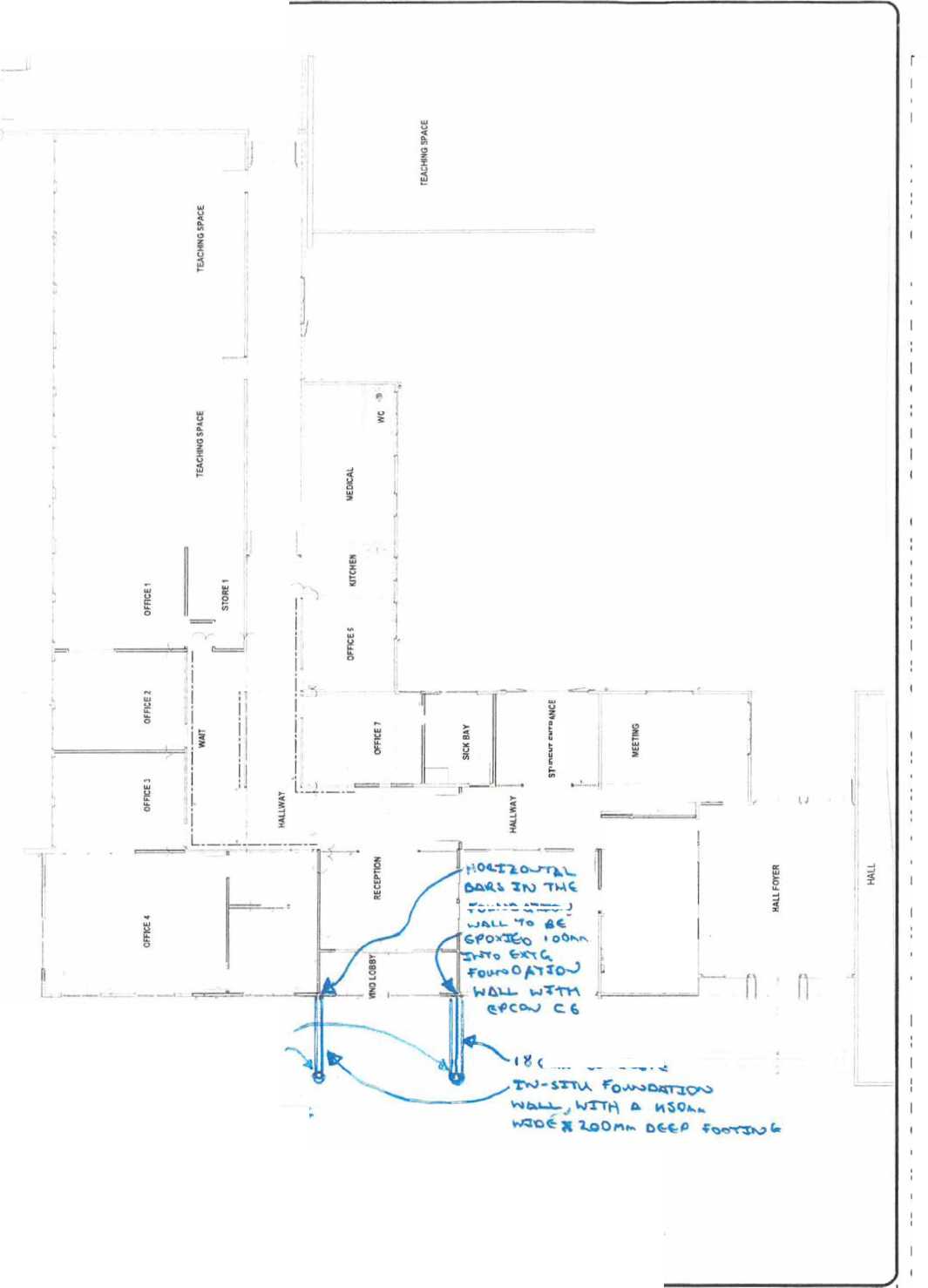
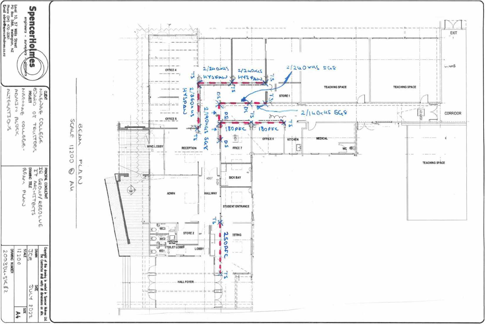 |
|
I^ĒāOIUI^^Ē MAWA@ēMēIMT- LAM® P IL A M IM 0 M @ - BM®VĒtfl!M@ = ^V^^QT^MAL - © D W 0 L - F II ® S |
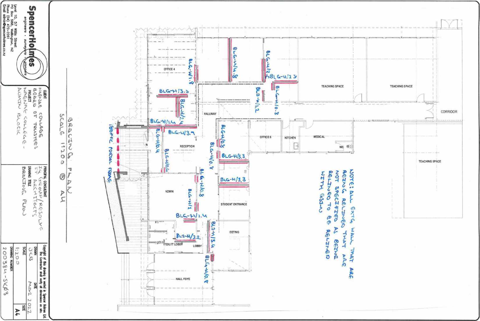 |
|
^BBQ^B^Q® I^AMA^ēMēMT^ LAM® IP L A M M 6 M ^ - ^M^^ē^^M^ - BT^®©7^^AL ° © 0 W 1 L = ^ 0 IP ē |
|
' ^v^-ni^coz ^V cr.i ZTOl Z,^W ^>OS- KUt uo MMMfels p ^p» pqr spaqiioo an PH "«PH nxi^ * pis* • ^f *W P W^ a ^ b a - 7 b ^ b s • T/^^BBJL^^^ia “ ^MBAa^^ims - & monm w i a @m v 7 -jLiM3Bfla®wMWBM a$a^©3a& 'OMtiJJOJ $ ^Vtjj AVUOJ 14 e» ^ t run 9MMVM Si's-5-1.1.'■'>»'? XX JA^QSdTj/^O^ 'OX WOW» 1MIMM |
'ir'^t-lTo-S L t^ 1x10^9 vj xv»a v -^^'V'QI ^'«'••a^N inroad 'S^-54^^4- JO -5mcg ^'^'V'cra VJCM^rt |
zu'oa'mupHM^uadBpiJiuipD |ftur] 19ZI-W» (MJ) «“Md ZN 'uoi6ui(p« Ba? «og Qd JWflS SHUM ZE '01 P*»l 
$jj>»ur6ua sa)uioH-i93uad$ >T^ ® ot:i 9W)s >g riXXGQi ē^^īTi ^^frQd ^AdCm
O k> CXMt '"OQVi 1>MQ MOW-? \ aa COn <$ 'S.TTd.faiS tloH 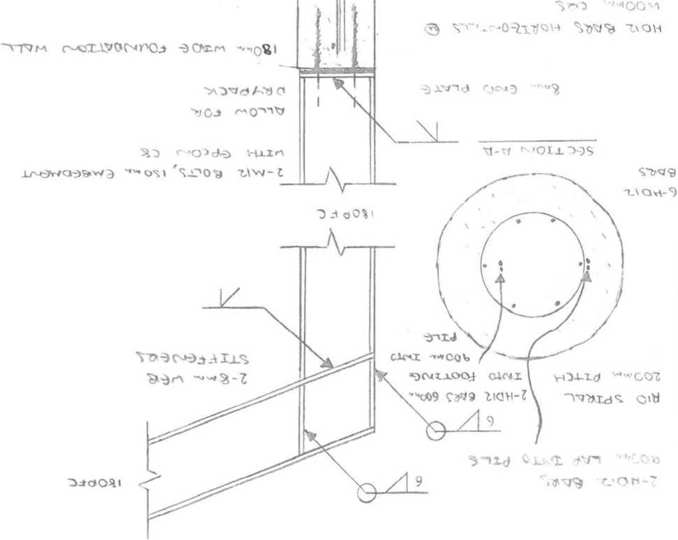
| ||||
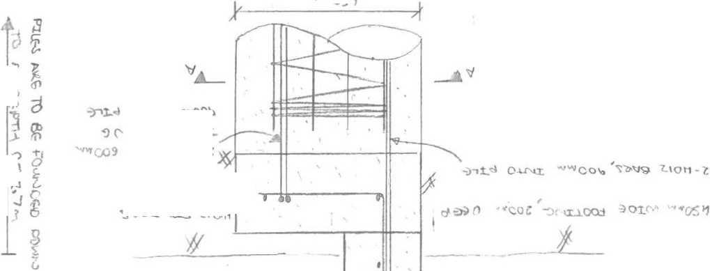
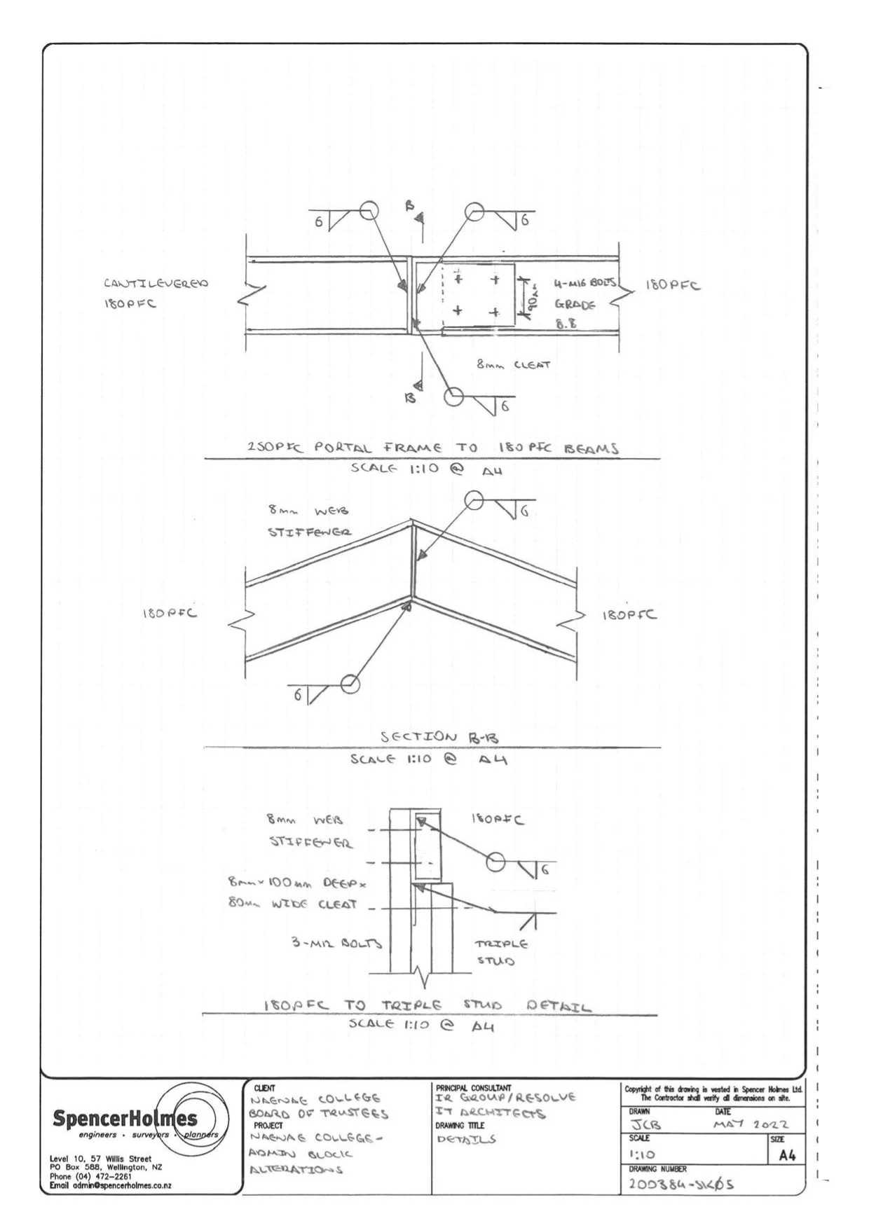 |
©©©©©©©ē MAMA^EUWSMir ° LAM© P L A M M 0 M © ° ©UMWEWŪM® - ©TM©©^©©AL = © I V B L - F B E Ē |
TTt^e.G« fiFAA-A
 |
Top plat <s |
|
I0TO | |
AroO GT \ IX)^

OOea^L-^.
TT^feG^L feFZXTO Dove^lG £F u\O
fcM
TXA^t^e^
F>€aaa
TOP PLhTG
COukQ Lt-
Stwq
SOOn^ SUsst JSWACfc stqaps e/«
SCALt IMO <S A<A
|
SpencerHomjes \ engineers * surveyors ^^/snpers J Level 10. 57 Willis Street PO Box 5843, Wellington, NZ Phone (04) 472-2261 ^ Email admirrO^ricerholmesxo ^ |
7---------------------- CUENT ^ Atr^KS^ COU^ CKjrC BOrxR^ Of "'‘lAASTOt^ PROJECT MA^^A.^. COiA_fcG,C, -hoMavP Cit^tA*, h-vr^ftKr xo^x |
PRINCIPAL CONSULTANT 'X(t ^JOiaF/k^OLV^ xt* aac torreeft drawn; tttle >«dJ> X |
|
Copyright of the towing is vested in Spencer Holmes lid The Contador tod writy d ^martsons on toe, | |||||||||
|
DRAWING NUMBER
ZOO^BU-^KfJ ^
^fSO^^^f MAWA@EMIFMT- LAM® PL A MM 0 N @ - ê^^\fĒVSM@ = BTffiHJ]®irUffiAlL - ® I V D L ° IF B ^ Ē
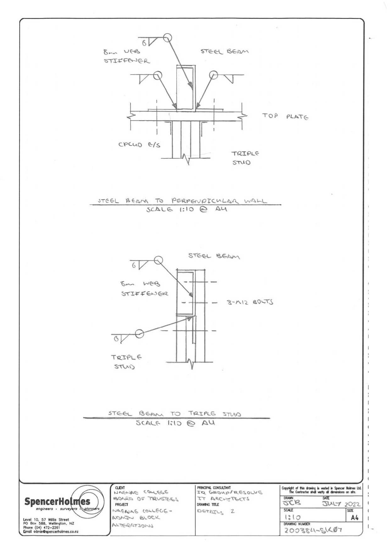 |
®EB©®N®E MANAGEMENT- LAN® PLANNING - GUJNTEVDNG - ®TN®GT®NAL - © II V II L ° NONE |

3 3 II 3 “ TUSH® ’ ^^^^^3>^^1^ - ^IMOAāA^m^ - ® IM Ō IM IM V 7 3 @ IM V 7 -AIMāW^&WMWIIW 33>^lM0B33
?07\S-*i?^.oi^
_________QUON 5N^
|
w |
O \ *1 rues | ||
|
A-Zoc |
not 31» |
30 Q MMIQ | |
‘9|K HO EUOtClfiUjp |D ^UM pp «pOipOQ ^
TH MUPH jiMds « pqm « 6^9 o« p *RMqq
|
« ^yMVOc, TUU OMMYWQ rx>^Xx\A JTyM XO. ^^QS 3?-J > o^O^ ^>1 IWiTlSNOO TWMdd |
'»1Q''^) r^Twcry - d-^^A-^^^ ^t^^mr* DlfOBd ^ ^5iir>7M- A*> «^wwoa ‘^‘“^'V'C'S ^'V^-JX/rM |
^ ZlTO3'£dUipl4J»3UOdB0qilJpD IpULQ^ i9EWa (#0) *»Md ZN 'uojBuiipm '099 *O0 Od ___ 1®WJS SHUM 4S '01 pA»n /$J»ŪUūj^ SjWaAJflfi ■ SJ^au/JStra i ssbjoHJaouads |
'^S SnxoNoi/j
|
\^vf^^ |
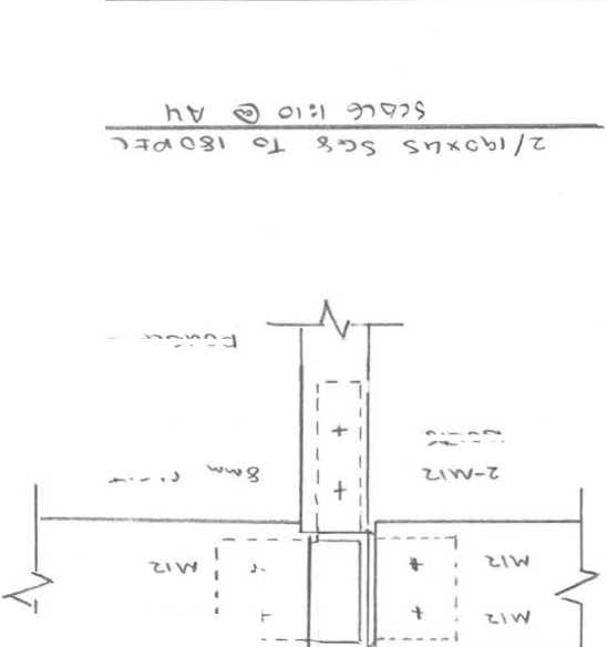
5f c** |
|
^C>o^\ |
Oms -3ts»yxoc1
JLV9T1'J
s/^
^V^S
0 4^09,1 CA- w^d“ā 74'dC^I
x«5$
\v> x o^* It
|
<>CMlH-5«k |
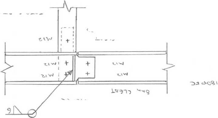 |
|
■&dc~<d4jrXA^ |
OvulS VMXO1
-iides*
APPLICATION FOR PROJECT INFORMATION MEMORANDUM AND/OR BUILDING CONSENT (FORM 2)
Section 33 or 45, Building Act 2004
THIS IS A PDF FILL-IN FORM COMPATIBLE WITH MOST PDF VIEWERS. IF YOU ENCOUNTER DIFFICULTY WITH ANY OF THE CONTROLS, TRY USING A DIFFERENT PDF VIEWER. CHROME IS FREE TO DOWNLOAD AND COMPATIBLE WITH THIS FORM.
HOW IT WORKS
All building work done in New Zealand must comply with the Building Code, and a building consent is often needed. Some building work is exempt from needing a consent. For more information go to www.building.govt.nz
Commercial and multi-unit building work will also need careful planning and may have additional requirements.
Your council can tell you about any district or regional plans that may require you to get resource consent or other permits.
WHEN YOU NEED A BUILDING CONSENT
The following list is a summary of building work that will need a consent, but you should always check with your local council to confirm.
-
• structural building - including additions, alterations, re-piling and some demolitions
-
• plumbing and drainage where an additional sanitary fixture is created
-
• relocating a building
-
• installing a wood burner
-
• retaining walls higher than 1.5 metres
-
• fences or walls higher than 2.5 metres, and all swimming pools and their associated fences
-
• decks, platforms or bridges more than 1.5 metres above ground level
-
• sheds greater than 30 m² in floor area (restrictions apply to sheds between 10 and 30 m².
You are breaking the law if you carry out building work that is not exempt and does not have a building consent. You may be fined up to $200,000 and, if work continues, a further fine of up to $20,000 for every day or part-day during which the offence continues.
Your council can also issue you a notice to fix for carrying out building work without consent, including instant fines of up to $1,000. They can remove the building work if it is dangerous or insanitary.
HOW TO APPLY
As a minimum, the documents listed below must be included in your application. Depending type of application, additional documents might be required or requested while the Council/Territorial Authority (TA)/Building Consent Authority (BCA) process your application.
-
• Proof of ownership
-
• Detailed drawings and plans
-
• Specifications.
HOW TO SUBMIT YOUR APPLICATION
Check with the Council/TA/BCA you are applying to for more information on how to submit your application. Electronic submissions may be available with the relevant Council/TA/BCA on the simpli.govt.nz website.
APPLICATION FOR PROJECT INFORMATION MEMORANDUM AND/OR BUILDING CONSENT (FORM 2)
Official Use Only
Section 33 or 45, Building Act 2004
-
1. WHAT ARE YOU APPLYING FOR?
Building Consent
Amendment to Building Consent
Project Information Memorandum (PIM) complete only sections 1-6 and 10-12
Staged Building Consent - Stage number ______ of ______ expected number of stages.
Building Consent for a National Multi-use Approval (MultiProof) - MultiProof Number ________________
® No O Yes - provide details
Have you discussed your application with the Council / BCA before making this application?
|
List PIM, building and resource consents related to this project (if any): |
Consent Number |
Description |
Are you applying for Owner-Builder exemption to complete the Restricted Building Work?
If Yes, complete and attach the 'Statutory Declaration as to Owner Builder Status (Form2B)'.
If No, complete and attach the 'Memorandum from Licensed Building Practitioner: Certificate of Design Work (form2A)'.
O No
O Yes
-
2. PROPERTY INFORMATION
Street address of the building:
For structures that do not have a street address, state the nearest street intersection and the distance and direction from that intersection
Naenae College 914 High Street
Avalon
Lower Hutt, 5011
Legal description of the land where the building is located:
State legal description as at the date of application and, if the land is proposed to be subdivided, include details of relevant lot numbers and subdivision consent
Lot:
1
DP:
18397
Building Name:
Admin Block
Level/ Unit number:
Location of building within the site/block number:
Front building (main entrance)
Current, lawfully established use:
Include the number of occupants per level and per use if more than 1. If the use was changed by the building work, state previous use
Education
Area:
Total floor area. Indicate area affected by the building work if less than the total area
400 m²
Current number of levels:
1
Current number of levels below ground:
0
Year first constructed:
Insert year. An approximate date is acceptable, e.g. the 1920s or 1960-1970
1950-1960
-
3. OWNER AND AGENT INFORMATION
Owner
Name of Owner:
Include title
Ministry of Education
Contact person: If not an individual
Frank Bourke (Agent)
Email:
enquiries.lowerhutt@educatio n.govt.nz
Mobile:
04 4638699
Alternative Phone:
Street address:
Level 2/19 Market Grove, Hutt Central, Lower Hutt 5010
Mailing Address:
If different from street address
PO Box 30177, Lower Hutt, 5040
Agent
If the application is made on behalf of the owner
Name of Agent:
IR Group
Contact person: If not an individual
Frank Bourke
Relationship to owner:
Project Manager
Email:
Mobile:
0274273471
Alternative Phone:
Street address:
Level 2 / 3 Swan Lane, Te Aro, WGTN
Mailing Address:
If different from street address
|
The first point of contact: |
✓ |
Agent |
Owner | ||
|
Who should we contact for invoicing? |
✓ |
Agent |
Owner | ||
|
Payee name for invoicing: |
NAENAE COLLEGE | ||||
|
4. WHO IS INVOLVED? In addition to the Designer, Architect and Engineers, provide the details of all licensed building practitioners who will be involved in carrying out or supervising the restricted building work. If these details are unknown at the time of the application, they must be supplied before the work begins. If you have additional roles to add, please use the table in Appendix A. | ||||||||||||||||||||||||||||||
| ||||||||||||||||||||||||||||||
|
Name: |
Nigel Ball |
Entity or Company: |
Resolve It Architects | ||
|
Licensing class/ Role: |
Architect |
LBP or Registration number: | |||
|
Email: | |||||
|
Street Address: |
171 Vivian Street, Te Aro, Wellington 6011 |
Mailing Address: If different from street address | |||
|
Contact numbers |
Mobile: |
04 830 2925 |
Other: | ||
-
5. THE SPECIFICS OF THE SITE
What is the wind zone?
OLow OMedium OHigh ©Very High ©Extra High ©Specific Design - Value _
What is the exposure zone?
©Low(B) ©Medium(C) ©High / Sea Spray(D)
Yes
No
Are you building in a zone that requires a land-use Resource Consent?
O
O
Does the site have any cultural or heritage significance, or is it a Marae?
O
O
Does the proposed building work cover two or more allotments?
O
O
Is it a sub-division?
O
O
Is the subdivision of an existing site involved? If yes, provide details below.
If a subdivision is proposed and you have not yet received an s224 certificate, the application will also need to provide any relevant information stating legal description as at the date of application and, if a subdivision is proposed, include details of the relevant resource consent number and any proposed lot numbers.
O
O
Is the building work over or adjacent to any road or public place?
O
O
Is there new or altered access for vehicles?
O
O
Are there new or altered connections to public utilities?
O
O
Are there public drains on the site?
O
O
Does the building work involve the disposal of stormwater or wastewater?
O
O
Is the building work over any existing drains or sewers or in close proximity to wells or water mains?
O
O
Is the site subject to natural or created hazards such as erosion, subsidence, flooding, slips, cut and fill or contamination?
O
O
Are there any alterations to land contours (e.g. earthworks)?
O
O
Are there new or altered locations and/or external dimensions of buildings?
O
O
Are there any other matters known to the applicant that may require authorisation from the Territorial Authority? Provide details below
O
O
Details from any of the above questions:
2021-11-02 Application For Project Information Memorandum and/or Building Consent
3
-
6. DETAIL OF THE BUILDING WORK
What building work are you doing? Select all that apply
Residential:
u
New detached dwelling
New Multi-residential dwelling
Plumbing works
Major alterations/additions (altering or attaching to the exterior of a building)
Minor alterations (only internal work)
New or relocation of a solid fuel burner Garage / detached carport
Other (provide detail below)
Commercial:
New commercial / industrial building
Seismic strengthening
Major alterations/additions (altering or attaching to the exterior of a building)
L
Minor alterations (only internal work)
Internal fit-out (including plumbing and ventilation)
Other (provide detail below)
Short description of the building work:
E.g. 4 Bedroom dwelling with multiple cladding types and attached garage. Limited to 340 characters.
Reconfiguration and upgrades to the interior of the administration building, including new entrance and deck.
Repitching and overlay of of the existing roof. Some associated cladding and window replacements.450
Does the project include Restricted Building Work?
© No O Yes
Proposed new total floor area:
400 m²
Number of levels after building work:
1
Number of levels below ground, after building work:
0
What is the intended life of the building?
O 50+ years OLimited life
Intended life of the building if 50 years or less:
years
Does the building work involve a swimming pool?
O No O Yes
Proposed use:
Building code clause A1 classified uses
OHousing
Detached dwellings Multi-unit dwellings
Group dwellings
OCommunal Residential
Community care unrestrained Community care restrained
Community service
OCommunal Non-Residential
Assembly Service Assembly care
O Commercial OIndustrial OOutbuildings OAncillary
The estimated value of the building work:
If an amendment, capture the original value of work. Capture the additional value in the next field.
$ 800000
Inc GST
If an amendment to a consent, what is the additional value?
$
Inc GST
Will the building work result in a change of use?
O No O Yes
- If Yes, please provide details of the new use:
Will there be any recladding?
O No
O Yes
Is this application related to a claim under the WHRS1 or FAP2 scheme? 1Weathertight Homes Resolution Service 2Leaky Homes Financial Assistance Package
O No
O Yes - If Yes, please provide the WHRS / FAP reference number(s):
Is your building consent application of a type defined in Gazette Notice1 and section 46 of the Building Act 2004?
Certain applications for building consent must be submitted to Fire and Emergency New Zealand's Fire Engineering Unit (FEU) for review. 1(New Zealand Gazette, 3 May 2012, Issue 49 page 1406)
O No
O Yes
-
7. SOLID FUEL BURNER INFORMATION
Does this application include the installation of a new or relocation of a solid fuel burner?
O Yes ® No — Go to section 8
|
Make of the heater/burner: |
Model of the heater/burner: | |||
|
Design: |
O Freestanding O Inbuild |
Type of fuel: | ||
|
Wetback connection: |
ONew O n/a OExisting |
Hearth construction type: | ||
|
Hearth thickness: |
mm |
Specify the fixings of the hearth: | ||
|
What is the floor constructed of? |
n/a |
Specify air gap between hearth and floor: |
n/a mm | |
|
Height of flue above roof ridge: |
mm |
Will the installation require new penetration through the roof or exterior wall? If yes, specify the material the penetration will be made through |
O No O Yes | |
|
Type of flue kit: | ||||
|
Will the flue termination be more than 3m from any structure, including neighbours buildings? |
O No O Yes |
Distance from outer flue shield to framing timbers: |
mm | |
|
Will the flue pass through more than one storey? |
O No O Yes | |||
|
Will the proposed appliance need to be installed closer to combustible material than manufacturers recommendations? |
O No — continue to section 8 O Yes | ||
|
Distance hearth projects from the front of the heater: |
mm |
Distance hearth projects from the side of the heater: |
mm |
|
Distance from the centre of the chimney to the walls: |
mm |
Distance from the back of the heater to the wall: |
mm |
|
Is the heater installed on an angle to the walls? |
O No O Yes | ||
|
Provide method of wall protection if required: | |||
-
8. THE BUILDING WORK WILL COMPLY WITH THE BUILDING CODE AS FOLLOWS:
-
• You are required to indicate what code clause(s) your building work complies with.
-
• Unless otherwise noted below, your application will be assessed under Acceptable Solutions.
-
• If you are using another means of compliance, please provide details of the standard(s) that your building work complies with and the means of compliance in the space provided. Use a separate sheet of paper if necessary.
-
• If you do not provide all the necessary information to show how your application complies with the Building Code, it will be returned unprocessed.
✓
B1 - Structure
✓
B2 - Durability
0
C1 – Outbreak of fire
C4 Movement to a place of safety
✓
L
C2 – Prevention of a fire occurring
C5 Access & safety for firefighting operations
✓ C3 Fire affecting areas beyond fire source C6 Structural stability
✓ D1 Access routes
L
D2 Mechanical installations for access
✓
E1 Surface water
✓
E2 External moisture
✓
E3 Internal moisture
□
0
F1 Hazardous agents on-site
F4 Safety from falling
F7 Warning systems
✓
0
0
F2 Hazardous building materials
F5 Construction & demolition hazards
F8 Signs
✓
□
F3 Hazardous substances and processes
F6 Visibility in escape routes
F9 Restricting access to residential pools
0
0
0
G1 Personal hygiene
G4 Ventilation
G7 Natural light
G10 Piped services
G13 Foul water
E
✓ ✓
G2 Laundering
G5 Interior environment
G8 Artificial light
G11 Gas as an energy source
G14 Industrial liquid waste
□
✓ ✓
G3 Food preparation & prevention of contamination G6 Airborne & impact sound G9 Electricity
G12 Water supplies
G15 Solid waste
0
H1 Energy efficiency
Backcountry Huts
Provide details of all Verification Methods being used. (Include relevant code clause and means of compliance)
Structural Work - B1/VM1
James Hardie Axon & Easy-Lap claddings - E2/VM1
Provide details of all Alternative Solutions being used. (Include relevant code clause and means of compliance or details of any waivers and modifications, including code clauses)
Beams specified by engineer as per detailed.
Alternative solution for E2 roof (Rooflogic Ultratherm warm roof with Fibertite KeEE membrane)
-
9. COMPLIANCE SCHEDULE
Are there any specified systems in the building? Residential cable cars are considered specified systems, see SS16
® Yes
O No — Go to section 10
You need to provide information on the specified systems contained on the compliance schedule for the building and, in the opinion of the personnel who installed them, are capable of performing to the performance standards set out in the building consent.
|
For more information on how to complete this section, see MBIE's Compliance Schedule Handbook | ||||||||
|
The following specified systems are contained on the compliance schedule for the building and, in the opinion of the personnel who installed them, are capable of performing to the performance standards set out in the building consent:
|
Specified System |
60 C *x LU |
"D CU i_ CU 4-» < |
3 0) z "D CU < |
■n <u o E <u oe |
(Ū C |
Performance Standards Acceptable Solution, Verification Method, Standard or specific document |
Inspection Inspection Procedures may be identified by a written description, or a reference to a Standard or other document |
Maintenance Maintenance procedures may be identified by a written description, or a reference to a Standard or other document |
Reporting Reporting procedures may be identified by a written description, or a reference to a Standard or other document |
Responsibility List persons/ companies for the adjacent procedures |
|
SS1 Automatic system for fire suppression |
O |
O |
O |
O |
O | |||||
|
SS2 Automatic or manual emergency warning systems for fire or other dangers |
O |
O |
O |
O |
O |
NZS 4512:2003 |
Monthly by IQP Annually by IQP |
Monthly by IQP Annually by IQP |
All tests and maintenance to be recorded in log books complying with th |
Wormald |
2021-11-02
Application For Project Information Memorandum and/or Building Consent
|
Specified System |
bo LU |
"D CU 4-» < |
3 O) Z "D < |
■n <u o E <u oe |
(Ū C |
Performance Standards |
Inspection |
Maintenance |
Reporting |
Responsibility |
|
SS3 Electromagnetic or automatic doors or windows | ||||||||||
|
SS3.1 Automatic doors |
o |
o |
o |
o |
o | |||||
|
SS3.2 Access control doors |
© |
o |
o |
o |
o |
C/AS2 Amendment 2 November 2020 3.15 and NZS 4239 |
By owner/occupier: Daily: Check doors are not locked, blocked, or barred By IQP: |
Monthly by owner Annually by IQP |
All tests and maintenance to be recorded in log books complying with th |
IPQ |
|
SS3.3 Interfaced fire or smoke doors or windows |
o |
o |
o |
o |
o |
C/AS2 Amendment 2 November 2020 3.15 and NZS 4178 |
By owner/occupier: Daily: Check doors are not locked, blocked, or barred By IQP: |
Monthly by owner Annually by IQP |
All tests and maintenance to be recorded in log books complying with th |
IPQ |
|
SS4 Emergency lighting systems |
o |
o |
o |
o |
o |
AS 2293 as amended by F6/AS1 Amendment |
Inspection and maintenance procedures as per AS 2293 Part 2 |
Monthly by owner Annually by IQP |
Monthly by owner Annually by IQP |
Wormald |
|
SS5 Escape route pressurisation systems |
o |
o |
o |
o |
o | |||||
|
SS6 Riser mains for use by fire services |
o |
o |
o |
o |
o | |||||
2021-11-02
Application For Project Information Memorandum and/or Building Consent
|
Specified System |
bo LU |
"D CU U 4-» < |
3 O) Z "D < |
■n > o E u oe |
(Ū C |
Performance Standards |
Inspection |
Maintenance |
Reporting |
Responsibility |
|
SS7 Automatic backflow preventers connected to a potable water supply |
o |
o |
o |
o |
o | |||||
|
SS8 Lifts, escalators, travellators, or other systems for moving people or goods within buildings | ||||||||||
|
SS8.1 Passenger-carrying lifts |
o |
o |
o |
o |
o | |||||
|
SS8.2 Service lifts |
o |
o |
o |
o |
o | |||||
|
SS8.3 Escalators and moving walkways |
o |
o |
o |
o |
o | |||||
|
SS9 Mechanical ventilation or air-conditioning systems |
o |
o |
o |
o |
o |
Fire and smoke control to AS 1668.1 |
Inspection and maintenance procedures as per AS 1851 |
Inspection and maintenance procedures as per AS 1851 |
Monthly by owner Annually by IQP |
Monthly by owner Annually by IQP |
|
SS10 Building maintenance units providing access to exterior and interior walls of buildings |
o |
o |
o |
o |
o | |||||
|
SS11 Laboratory fume cupboards |
o |
o |
o |
o |
o | |||||
2021-11-02
Application For Project Information Memorandum and/or Building Consent
|
SS12 Audio loops or other assistive listening systems | ||||||||||
|
SS12.1 Audio loops |
o |
o |
o |
o |
o | |||||
|
SS12.2 FM radio frequency and infrared beam transmission systems |
o |
o |
o |
o |
o | |||||
|
SS13 Smoke control systems | ||||||||||
|
SS13.1 Mechanical smoke control |
o |
o |
o |
o | ||||||
|
SS13.2 Natural smoke control |
o |
o |
o |
o |
o | |||||
|
SS13.3 Smoke curtains |
o |
o |
o |
o |
o | |||||
|
SS14 Emergency power systems for, or signs relating to, a system or feature specified in SS1-13 | ||||||||||
|
SS14.1 Emergency power systems |
o |
o |
o |
o |
o | |||||
|
SS14.2 Signs for systems |
o |
o |
o |
o |
o |
F8/AS1 Amendment 4 January 2017 |
Monthly by owner Annually by IQP |
Monthly by owner Annually by IQP |
By owner/occupier: Monthly: Ensure signs are in plac | |
2021-11-02
Application For Project Information Memorandum and/or Building Consent
|
Specified System |
bo LU |
"D CU 4-» < |
3 O) Z "D < |
■n <u o E <u oe |
(Ū C |
Performance Standards |
Inspection |
Maintenance |
Reporting |
Responsibility |
|
SS15 Any or all of the following systems and features, so long as they form part of a building's means of escape from fire, and so long as those means also contain any or all of the systems or features specified in clauses 1 to 6, 9, and 13: | ||||||||||
|
SS15.1 Systems for communicating spoken information intended to facilitate evacuation; and |
o |
o |
o |
o |
o | |||||
|
SS15.2 Final exits As defined by clause A2 of the building code |
o |
o |
o |
o |
o |
NZBC C/AS1 Fire Safety or to the standard applicable at the time of install |
All tests and maintenance to be recorded in log books complying wi |
Monthly by Owner or agent Annually by IQP |
Monthly by Owner or agent Annually by IQP |
IPQ |
|
SS15.3 Fire separations |
o |
o |
o |
o |
NZBC C/AS1 Fire Safety or to the standard applicable at the time of install |
Check integrity of wall & ceiling linings, door seals and closers. |
Monthly by Owner. Annually by IQP |
Monthly by Owner. Annually by IQP |
IPQ | |
|
SS15.4 Signs for communicating information intended to facilitate evacuation |
o |
o |
o |
o |
o |
F8/AS1 Amendment 4 January 2017 |
By owner/occupier: Daily: Check doors are not locked, blocked, or barred Weekly: As per dail |
By owner/occupier: Monthly: Ensure signs are in place where required, are legible, clean, and |
By Owner or suitably qualified person. |
IPQ |
|
SS15.5 Smoke separations |
o |
o |
o |
o |
o | |||||
|
SS16 Cable car All buildings with a cable car, including single residential buildings, require a compliance schedule. |
o |
o |
o |
o |
o | |||||
2021-11-02
Application For Project Information Memorandum and/or Building Consent
-
10. HAVE YOU ATTACHED ALL THE REQUIRED DOCUMENTS?
Please include the following document as part of your application. Additional documents might be requested as part of the assessment of your application. Incomplete applications may be returned unprocessed.
Proof of ownership
® Copy of Record of Title
O Copy of Lease Agreement
O Agreement for Sale & Purchase
O Other document showing the full name of the legal owner(s)
Project Information Memorandum (PIM)
Certificate attached to PIM
Development Contribution Notice
✓
Plans, specifications and other supporting information (Include information on the compliance method, e.g. where the work deviates from an Acceptable Solution method.)
Memorandum from Licensed Building Practitioner – Certificate of Design Work (Form 2A)
Statutory Declaration as to Owner Builder Status (Form 2B)
-
11. APPLICATION FEES
The Council/ Building Consent Authority (BCA)/ Territorial Authority (TA) will charge a fee for your application and any subsequent work involved in processing your application. The fee will include statutory levies payable to BRANZ and the Ministry of Business, Innovation and Employment.
-
12. ACKNOWLEDGEMENTS
The information you have provided on this form is required so that your application or the building consent it relates to can be processed under the Building Act 2004. The Council, Territorial Authority (TA) or Building Consent Authority (BCA) collates statistics relating to building work and has a statutory obligation to provide information to third parties. The information is stored on a public register, which must be supplied to whoever requests the information. Under the Privacy Act 2020, you have the right to see and correct personal information the Council, TA and BCA hold about you.
In providing this information, you agree to your details being used for customer surveys carried out by the Council, TA or BCA.
All the information contained in the application is, to the best of my knowledge, true and correct.
I request that you issue a project information memorandum, project information memorandum and building consent, or building consent for the building work described in this application.
[✓ I understand that this application is to be assessed against Acceptable Solutions unless otherwise stated in section 8.
-
[✓ I understand that work must not commence until the building consent is issued and uplifted.
[✓ I understand that this application may only be made with the owner's approval.
|
Full name: |
Frank Bourke |
|
Signature: Digital signatures acceptable |
Digitally signed by Frank Bourke Frank Bourke Date: 2022.08.28 13:12:09 +12'00' |
|
Date: |
21-07-2022 |
|
Appendix A – List of those involved in the build Complete if additional space is required for Section 4 | |||||||
|
Name: |
TBC |
Entity or Company: | |||||
|
Licensing class: |
LBP or Registration number: | ||||||
|
Email: | |||||||
|
Street Address: |
Mailing Address: If different from street address | ||||||
|
Contact numbers |
Mobile: |
Other: | |||||
|
Name: |
Entity or Company: | ||||||
|
Licensing class: |
LBP or Registration number: | ||||||
|
Email: | |||||||
|
Street Address: |
Mailing Address: If different from street address | ||||||
|
Contact numbers |
Mobile: |
Other: | |||||
|
Name: |
Entity or Company: | ||||||
|
Licensing class: |
LBP or Registration number: | ||||||
|
Email: | |||||||
|
Street Address: |
Mailing Address: If different from street address | ||||||
|
Contact numbers |
Mobile: |
Other: | |||||
|
Name: |
Entity or Company: | ||||||
|
Licensing class: |
LBP or Registration number: | ||||||
|
Email: | |||||||
|
Street Address: |
Mailing Address: If different from street address | ||||||
|
Contact numbers |
Mobile: |
Other: | |||||
|
simph 2021-11-02 Application For Project Information Memorandum and/or Building Consent | |||||||
MULTI RESIDENTIAL DWELLING, INDUSTRIAL OR COMMERCIAL BUILDINGS CHECKLIST

Adobe Reader is required to fill this form out online. Download for free: get.adobe.com/reader/
Address: Naenae College, 910 High Street, Avalon, Lower Hutt
-
■ This checklist shows you the information that has to be supplied with your building consent application. Please attach one (1) copy of the following information with your completed application form.
-
■ Tick each relevant box as you attach the information. If the box is not relevant to your application, leave it blank.
-
■ A guidance document is available to help complete the section in the application form on ‘means of compliance’ for each building code clause.
You can submit this checklist electronically with the rest of your application by selecting ‘Apply for it’ under the ‘Do it here’ menu at huttcity.govt.nz. The address to post or deliver your application is:
Environmental Consents Division, Hutt City Council, 30 Laings Road, Private Bag 31912, Lower Hutt 5040.
For additional help go to: huttcity.govt.nz/apply-online/ or phone 04 570 6666.
Once you have attached all the required information, please check for completeness as an incomplete application or lack of any supporting information will mean that your application cannot be accepted for processing.
0 a Building Consent Application form (one (1) copy)
Completed and signed by the owner or by an agent on behalf of the owner.
0 b Signatures
-
c Licensed Building Practitioners engaged
0 d Contacts
-
e Change of use
-
f Cultural Heritage
-
0 g Estimated Value
h List building consents previously issued
-
0 i Clearly noted email address
0 j Proof of ownership (one (1) copy)
One recent copy of current certificate/s of title (i.e. not older than three (3) months) or where applicable one copy of purchase agreement (if recently purchased) or one copy of relevant portions of current lease.
k Consent notices
l Easement notices
Environmental Consents | Hutt City Council | 30 Laings Road, Private Bag 31912, Lower Hutt 5040 | huttcity.govt.nz | 04 570 6666
ECB-FORM-337 | June 2019
m Building over two allotments
n Geotechnical reports
-
o Penetrometer tests and results
0 p Locality plan (1:500) showing:
Physical location of the subject building in relation to streets or landmarks, north point, name of building and Lot and DP number.
Inspections and monitoring - details of proposed inspection regime including:
-
q Monitoring by Council officers
0 r Professionals eg, Architects, certification to be supplied on completion
0 s Engineers, certification to be supplied on completion
-
□ t Surveyors, certification to be supplied on completion
u Product statements and other documentation to be supplied on completion.
Application fee
0 v Applications will not be accepted without payment of the appropriate fees. Fees payable are set out in the published fee schedule of Council that has jurisdiction over the project site.
Complete for all projects involving demolition of significant parts of buildings or the demolition or removal of whole buildings that are three or more storeys.
Note: Where the project is ONLY for the complete removal or demolition of a building you are not required to complete any further sections
0 a Means of barricading the site
Provide details of temporary barriers, gates which swing inwards or other means of restricting public access to the area
b Proposed tipping location for demolition materials (address/landfill)
c Hazardous building materials
Provide safety plan detailing the safe handling and disposal of hazardous materials
d Site management plan covering management to control silt run off, noise and dust
e Proposed destination for relocated building
f Access to and from the site (including use of kerb and crossings)
g Specify termination of existing services:
-
■ Water
-
■ Sewer
-
■ Stormwater
Details about the building such as:
h Number of storeys, type of materials the building is constructed of (note: Photographs of the building would be useful)
0 i The extent of your work. You will need to contact the relevant service authorities specified below to advise them of the extent of:
Electricity, gas, drainage, water, transport, telecommunications, cable television or any other services that may be affected.
j Transportation of relocated building
You will be required to contact and provide details to Council's Transportation and Traffic Department
k Does the relocated building have a code compliance certificate from where it has been removed
0 l Existing wind zone for the building
Existing floor plan (1:100/1:50) showing:
0 a Dimensions of internal floor plate
0 b Location of exits
c Location and dimensions of lifts and lift cars including doors
d Location and dimensions of exit stairs or exit ways
0 e Exit door sizes
0 f Location and dimension of toilets and cleaners sink
0 g Reasonably practicable
Your proposal is required to fully comply with the building code. Where upgrading to fully comply with the building code for the above is not proposed you are required to supply supporting documentation making the case as to why it is not reasonably practicable to do so.
0 h Means of escape from fire
Assessment of means of escape for the whole building including floor plans showing egress routes to safe place. The assessment must incorporate a statement that the assessor is suitably experienced /qualified and has carried out a site inspection as part of the assessment.
0 i Accessibility (for buildings/uses listed in schedule 2 of the building act 2004) assessment of access
and facilities for people with disabilities for the whole building. The assessment must incorporate a statement that the assessor is suitably experienced/qualified and has carried out a site visit inspection as part of the assessment.
Application for discretion re upgrades (pursuant to section 112(2) of the building act 2004) including:
j Supporting information as to why the project would not proceed if the building was required to
comply.
k Description of improvements proposed related to means of escape from fire and access and
facilities for people with disabilities.
Complete for all existing buildings where the proposal will change the established use of all or part of the building.
-
□ a Fire assessment
In addition to the assessment of means of escape documentation must also include assessment of the whole building for structural stability in fire and protection afforded to other sleeping areas and other property.
-
□ b Structural assessment
Assessment against non-specific codes (NZS 3604 and NZS 4229) or engineering assessment included as part of the structural specific design.
-
□ c Sanitary facilities
Assessment of existing facilities within the building comparative to current code and levels of amenity provided by the Acceptable solutions
-
□ d Additional household units
An assessment of the building is required with respect to all building code clauses. If the proposal is for the project to meet anything less than full compliance with any clauses of the building code.
-
□ e Your application must clearly state your reasoning, with supporting documentation, and show how you will meet the highest level of compliance that can be considered reasonably practicable.
Complete for all buildings with uses listed in Schedule 2 of the Building Act 2004.
Access and facilities for the disabled (1:100/1:50) for the whole building showing:
-
□ a Access routes (footpaths, ramps, landings)
-
□ b Accessible toilet compartment including dimensions, location and height of fittings (toilet pan, basin, urinal, shower)
-
□ c Width of accessible routes
-
□ d Lift details
-
□ e Accessible stairs including details of handrails, stair risers and treads
-
□ f Accessible low height counters (including reception)
-
□ g Accessible car parks
Complete for all new buildings, or existing buildings where the footprint of the building will change or where an additional storey is being added
0 a Site Plan (1:100) showing:
Dimensions of all boundaries, north point, finished floor levels, ground contours (extended to boundaries) and/or levels, site area, street name and number, Lot and DP number, outline of building and distances to boundaries. Include on the site plan the designated wind zone of the site (eg, specific design, extra high, very high, high, medium or low)
b Foundation plan (1:100/1:50) showing:
-
■ dimensions of all new foundations
-
■ sub-floor, including bracing
-
■ footing details
-
■ if a concrete slab, show basic details including reinforcing and contractions joints
-
■ piles and footings
-
■ if the addition is an upper storey show details on upgrading existing foundations, joints, piles, etc
-
■ indicate ventilation to sub floor spaces
c Subfloor bracing
Provide subfloor bracing plan and calculations for all piled structures. Where the structure is specifically engineered, this should be included with the structural calculations.
Subfloor bracing plan and calculations are required where an additional storey is to be added.
d Foundation details
Details including reinforcing and connections
Complete for new buildings and for projects with existing walls removed or new walls added
0 a Proposed floor plans (1:100/1:50) showing:
-
■ Location of partitions
-
■ Room dimensions
-
■ All designated spaces
-
■ Plan of complete floor showing where work is both taking place, if altering existing plans of both existing and new work
b Lighting plan (1:100/1:50) showing:
-
■ Illuminance at floor level of total wattage required
c Bracing plan (1:100/1:50) showing:
-
■ Bracing details and calculations for wall bracing
-
■ Location, type and number of bracing elements
-
■ If the bracing was specifically designed by a structural engineer, provide calculations (required for specific design wind zones and lateral distribution of upper floor loads where lower storey bracing is provided in walls beyond the upper storey footprint)
d Sections and details (1:50/1:20/1:10) showing:
-
■ Stairs, handrails, decks and decking
-
■ Insulation systems and materials to floors, walls and roof
-
■ Barriers providing safety from falling. Specific engineering design required where detail does not comply with the MBIE Barrier Guide
-
■ Details of fire rated partitions from floor to underside of floor above (if more than one fire cell)
-
■ Details of sound rated partitions and floor/ceiling construction
-
■ Framing sizes, beams, lintels, trusses including fixing and other structural items. Lintels carrying point
loads require specific design
-
■ Roof cladding, eaves, fascias, gutters, flashings to openings
-
■ Fire rated systems on all walls in relation to boundary distance (calculations required)
-
■ Stud heights of rooms and total height from lowest ground floor level to top of ridge
-
■ Truss layout supported by design certificate and design of fixing details and load path to ground
-
■ Retaining wall details eg, type, height of retained ground, relationship to boundary, waterproof membrane and proposed drainage
e Product certification
-
■ Supply copies of product certificates relied on as compliance documents
f Alternative solutions: if the proposal uses products or systems that are not covered in the acceptable solutions of clause E2 of the building code:
-
■ Provide supporting current information, including independent test results (full signed reports), case studies, expert opinion (including evidence of experience/qualification, basis for forming opinion, and statement of independence) etc to demonstrate compliance.
Complete for all projects incorporating specific structural design. Refer to Council's building consent producer statements policy and procedure (ECB-POL-002)
a Structural calculations
-
■ If any design work required the services of a structural engineer, attach one (1) copy of the calculations
with this application along with structural drawings.
-
■ The calculations must be prefaced with information explaining the design philosophy and justification of assumptions and methodologies used in analysis.
b Producer statements
-
■ If this application for consent relies on any producer statements certifying compliance with the New
Zealand Building Code, a copy must be attached with this application. (note all structural producer statements are required to have accompanying calculations)
-
□ c ■ For large projects, a minimum professional indemnity insurance of $500,000 is required.
Complete for all new buildings and for existing buildings where there are alterations to the external shell.
0 a Elevations (1:100/1:50) showing:
-
■ Accurate lines from boundary to boundary on each elevation, relevant District Plan daylight control lines, the maximum height on each elevation, location of door and window openings, fixed and opening sashes, sill heights, floor levels in relation to ground levels, exterior cladding nominated to all elevations, down pipes and spouting, ventilators to sub-floor area (suspended floors only).
b Risk assessment (Risk matrix in E2/AS1 may be used)
-
■ Consider exposure, design and detailing to support appropriate selection of cladding.
-
■ Design outside the scope of E2AS1 required to be supported with specific engineered design.
0 c Roof and cladding details
-
■ Provide details around all penetrations/joinery and other junctions at a level appropriate to the level of risk.
d Product certification
-
■ Supply copies of product certificates relied on as compliance documents
e Alternative solutions
-
■ If the proposal uses products or systems that are not covered in the acceptable solutions of clause E2 of the building code provide supporting current information including independent test results (full signed reports), case studies, expert opinion (including evidence of experience/qualification, basis for forming opinion, and statement of independence) etc to demonstrate compliance.
Complete for all projects with new installation or alteration of plumbing or drainage services
Plumbing and drainage plan (1:100) showing:
-
■ (Note: if you have supplied drainage details for surface water disposal on the site plan, no drainage plan is required)
-
■ Easements identified in Certificate of Title
-
■ Consent notices relating drainage in certificate of title fixtures and fittings, hot water system(s)
-
■ Nominate plumbing/drainage design to be installed
-
■ If the building is more than one storey with sanitary fittings on upper floors, provide an isometric layout showing wastes, pipes and falls
-
■ Drainage layout with inspection bends and junctions indicated for both sewer and stormwater
-
■ Any other drainage on site including Council mains and retaining wall field drains ventilation of sanitary rooms
-
■ Ventilation of sanitary rooms
-
■ HVAC drawings
-
■ Trade waste pre-treatment system
-
■ Location and details of back flow prevention devices
Complete for all applications
0 a Fire report
-
■ Discussing the philosophy behind the proposal and demonstrating compliance with the building code. It is sometimes useful for existing buildings to include the building score sheet for the building.
b Proposed fire protection plan (1:100/1:50) showing: (if applicable).
-
■ Smoke alarm, thermal heat detectors
-
■ Sprinkler system
-
■ Fire alarm sounders
-
■ Any 'protected' path
-
■ Thermal (heat) detectors
-
■ Fire hose reels
-
■ Dry or Wet risers
-
■ Fire alarms call points and sounders
-
■ Alarm panel
-
■ Final exits
-
■ ‘Open path’ travel to exits
-
■ Method or systems for fire rating penetrations through or between fire cells
-
■ Fire appliance route to emergency access to the building
-
■ Proposed surface finishes specifications
-
■ Proposed passive fire rating systems
-
■ Proposed backflow preventers
-
■ Smoke control systems
-
■ External fire spread considerations
-
■ Emergency lighting
-
■ Signage
c Alternative solutions
-
■ Where the proposal is to meet the requirements of the building code by any means other than those covered in the compliance documents, provide a supporting, current, signed design report including independent test results, calculations and/or computer modelling (indicating the validity of assumptions and applicability to project).
-
■ Consideration of various scenarios (indicating that they cover worst case scenarios) and comparison with the levels of safety offered by compliance with acceptable solutions.
-
■ The designer must have established experience/qualifications. For alternative solutions that deviate significantly from acceptable solutions, independent peer review may be required.
d Reasonably practicable
-
■ The proposal is required to meet full compliance with the building code. Where upgrading to fully comply with the fire clauses of the building code is not proposed you are required to supply supporting documentation, making the case as to why full compliance is not reasonably practicable. Refer to Ministry of Business, Innovation and Employment Code words 32.
e FENZ (Fire and Emergency New Zealand) Referral
-
■ Does the proposal meet the criteria of the Gazette notice and need to go to FENZ? A working definition of a ‘minor effect’ is that it does not impact on the effectiveness of a sprinkler system or any other specified fire safety system that would require a change to the compliance schedule.
-
12. SPECIFICATIONS
Complete for all applications
Note: The specification must be specific to the project and cover all aspects of the proposed work.
0 Specification
-
■ Elements of structure (size, spacing, timber strength grade treatment)
-
■ Exterior engineered steel treatment for exterior use
-
■ Plumbing and drainage materials and design that installation is to comply with wet area surfaces
-
■ Flooring slip resistance specifications
-
■ Glazing/Safety glazing NZS (4223)
-
■ Quality Assurance programmes
-
■ Ventilation systems
-
■ Appraisals and certification certificates for all products
-
■ Proprietary fixings specifications or load capabilities and anti-corrosion treatment of fixings
-
■ External claddings specifications
-
■ Manufacturer producer statements
-
■ Wall claddings specifications
-
■ Roof cladding specifications
-
■ Flashing tapes specifications
-
■ Flashing systems and dimensions
-
■ Roof profile and specifications
-
■ Membranes (roofs and decks)
-
■ Tanking specifications
-
■ Joinery required standard and finishes
-
13. H1 ENERGY EFFICIENCY
H1 analysis including methodology and calculation
Analysis for HVAC, air flow ,solar gains and lighting energy where applicable
-
14. COMPLIANCE SCHEDULE
Complete for all buildings that contain systems or features that are required
New compliance schedule for the proposed building work
Provide a list of the following:
-
■ all specified systems to be installed in the building;
-
■ details of the systems;
-
■ proposed maintenance and testing regime for inclusion in the compliance schedule.
Amendment to an existing compliance schedule for the proposed building work
Provide a list of all specified systems that are being:
a altered or added in the course of the building work, details of the systems, proposed maintenance and testing regime for inclusion in the compliance schedule, or
b removed from the building in the course of the building work and an explanation of why this is happening.
Complete for all buildings
Gantries and hoardings
-
■ Provide details of barriers for the protection of public and for restricting public access to site
-
■ Details of gantries, scaffolding and hoardings
-
■ Cover letter, site specific description of health and safety work to be carried out
Certificate Application if required
Site management plan covering
-
■ Hazardous building materials report
Provide safety plan detailing the safe handling and disposal of hazardous materials.
-
■ Delivery and storage of materials, management to control silt run off, noise and dust, traffic management and parking.
Complete for all projects where the building use involves the storage, or use of, or processing with hazardous substances, including explosive, radioactive, toxic or flammable materials and compressed gases
Details
-
a Details of the materials used or stored, their hazardous substance classification (HSNO) report
b Individual container size and aggregate volume HSNO report
c Name of test certifier and HSNO scope covering
Plans and specifications describing
d Spaces where hazardous substances are stored and used and the method of disposal of waste
e Consideration of containment, pressure relief, electrical hazardous area zoning and ventilation
Fire Report
f Include specific consideration of these activities
Complete for all projects with an intended use including the manufacture, storage, preparation or sale of food products
Food premises
Hair salons
Doctor surgeries
Early childcare facilities
Health clinics
Dentistry
Funeral premises
Details:
-
■ Indication of type of business, including general food types to be prepared and beverages to be served
-
■ Water supply and sewage disposal connecting to town supply. Full details will be required if private
system proposed
-
■ Number of staff
-
■ Number of patrons (seated and standing)
-
■ Full details of surface finishes in food preparation, cooking, servery, storage and dish wash areas
-
■ Full details of location of all appliances and fixtures in food preparation, cooking, servery, storage
-
■ Dish wash areas including fridges, freezers, joinery, plumbing fittings and extract hood
-
■ Designation of proposed use for each area
-
■ Ventilation
-
■ Floor coverings
The issue of a building consent does not relieve the owner of any duty or responsibility under any other act. Please check with your local territorial authority regarding the requirement for other approvals required and fees payable. These may include:
Consents under the Resource Management Act
Vehicle access
Road openings
Health licensing
Liquor licensing
Trade waste licensing
Earthquake strengthening requirements
Heritage New Zealand
GHD easements, water meters and backflow devices
Wellington Water, services and inundation
Greater Wellington Regional Council, inundation
0 Ministry of Education
A guidance document is available to help complete the section in the application form on ‘means of compliance’ for each building code clause.
COMPLIANCE SCHEDULE
Section 103, Building Act 2004
huti^ty
^^ TE AWA KAIRANGI
THE BUILDING
|
Street address: |
914 High Street Building name: NAENAE COLLEGE AVALON 5011 |
|
Level/unit number: |
Ground level + Level 1 Location within site or Refer to page 9 (Special Needs Unit: Single level) block number: |
|
Year first constructed: |
(Special Needs Unit: 2013) Intended life of the Indefinite building if 50 years or less: |
|
Current lawfully established use: |
COLLEGE / SPECIAL CARE FACILITY Occupancy: 1886 School (1775) SNU (111) Fire Hazard Class: 2 Purpose Group: CL / SC |
|
Legal description of land: |
Pt LOT 1 DP 19671 |
THE OWNER
|
Name: |
Ministry Of Education |
Street address or registered office: |
C/- ARGEST Ground floor 155 The Terrace Wellington Central Wellington 6011 |
|
Contact person: |
Rob Wilson (AGENT) |
Phone numbers: | |
|
Mailing address: |
C/- ARGEST |
Landline: |
04 472 7905 (AGENT) |
|
PO Box 10145 The Terrace |
Mobile: |
029 472 7905 (AGENT) | |
|
Wellington 6143 |
Daytime: |
04 472 7905 (AGENT) | |
|
Email: |
rwilson@argest.com (AGENT) |
After hours: |
0800 274 378 (AGENT) |
|
Website: |
www.argest.com (AGENT) |
Fax number: |
04 473 1111 (AGENT) |
Compliance Schedule No: CS656
1 of 14
SUMMARY OF SPECIFIED SYSTEMS
|
SS1 |
- Automatic systems for fire suppression |
|
SS2 |
- Automatic or manual emergency warning systems for fire or other danger |
|
SS3/3 |
- Interfaced fire or smoke doors or windows |
|
SS4 |
- Emergency lighting systems |
|
SS7 |
- Automatic back-flow preventers connected to a potable water supply |
|
SS8/1 |
- Passenger carrying lifts |
|
SS9 |
- Mechanical ventilation or air conditioning systems |
|
SS11 |
- Laboratory fume cupboards |
|
SS14/2 |
- Signs for systems |
|
SSI 5/2 |
- Final exits |
|
SS15/3 |
- Fire separations |
|
SSI 5/4 |
- Signs for communicating information intended to facilitate evacuation |
|
SS15/5 |
- Smoke separations |
|
Location |
Acceptable solution |
Risk Group |
Escape lieight |
Area m- |
Occupant density nr p |
Occupant loads |
|
Classroom 1 |
C7AS4 |
CA |
0 |
80 |
2 |
40 |
|
Classroom 2 |
C/AS4 |
CA |
0 |
74 |
2 |
37 |
|
Tech room |
C/AS4 |
CA |
0 |
38 |
10 |
4 |
|
Recording room |
C/AS4 |
CA |
0 |
23 |
10 |
3 |
|
Staff room |
C/AS4 |
CA |
0 |
20 |
5 |
4 |
|
Studio 1,2 & 4 |
C/AS4 |
CA |
0 |
44 |
10 |
5 |
|
Store, lobby etc |
C/AS4 |
CA |
0 |
0' | ||
|
Total occupant load |
93 | |||||
|
Music Hall and |
C/AS4 |
CA |
0 |
400 |
- |
700 | |||
|
Storage |
C/AS4 |
CA |
0 |
74 |
2 |
o' | |||
|
Music/Dance/Drama Performance |
C/AS4 |
CA |
0 |
100 |
2 |
50' | |||
|
Total occupant load |
700 | ||||||||
|
G2 |
Library |
320 m2 |
10m2/person |
32 | |||||
|
Teaching laboratories |
440 m2 |
5 m’/peraon |
88 | ||||||
|
Offices |
61 m2 |
10 m2/porson |
7 | ||||||
|
G3 |
Workshop |
96 m2 |
10m2/person |
10 | |||||
|
G4 |
Classrooms |
328 m2 |
2 m2/porson |
164 | |||||
|
G5 |
Classrooms |
198 m2 |
2 m2/person |
99 | |||||
|
U1 |
Staff room |
193 m2 |
5 m’/person |
39 | |||||
|
Classrooms |
241m2 |
2 m’/person |
121 | ||||||
|
U2 |
Classrooms |
292 m2 |
2m*/person |
146 | |||||
|
U3 |
Classrooms |
352 m2 |
2 m2/person |
176 | |||||
|
U4 |
Classrooms |
200 m2 |
2 m’/person |
100 | |||||
SPECIFIED SYSTEMS
|
System or sub-system |
Performance standards |
Inspection, maintenance & reporting procedures |
|
SS1 - Automatic systems for fire suppression | ||
|
Fire sprinkler system Only at Special Needs Unit TYPE 7 |
NZS 4541:2007 Automatic Fire Sprinkler Systems |
NZS 4541:2007 Part 12: Routine Testing, Maintenance and Inspection Inspections and maintenance by IQP |
|
SS2 - Automatic or manual emergency warning systems for fire or other danger | ||
|
Naenae College buildings Vigilant Tyco Automatic fire alarm (manual call points with thermal and smoke detection) TYPE 4 - MX1 Analogue Addressable Fire Panel |
NZS 4512:2010 Fire detection and alarm systems in buildings |
NZS 4512 Part 6: Maintaining Systems in Compliance and good working order Testing: Monthly by IQP Survey: Annually by IQP Survey tests must include the interface with the operation of Smoke Stop Doors by the activation smoke detectors on either side of the smoke door. |
|
Special Needs Unit Automatic fire alarm (manual call points with smoke detection) TYPE 4 - Notifier Analogue Addressable Fire Panel Visual and Audio alarms. |
NZS 4512:2010 Fire detection and alarm systems in buildings |
NZS 4512 Part 6: Maintaining Systems in Compliance and good working order Testing: Monthly by IQP Survey: Annually by IQP Survey tests must include any interfaces with operation of smoke/fire control or egress route doors or lifts where present. |
|
SS3/3 - Electromagnetic or automatic doors or windows | ||
|
Electromagnetic held-open type released on fire alarm (fire / smoke control door) Also at Special Needs Unit (note: some rooms are provided with electric mortise locks, i.e. delayed action unlocking devices) |
AS/NZS 1905.1:1997 |
Inspections: Monthly by Owner to ensure the correct release of hold open devices on receipt of signal from Emergency Warning System or operation of associated smoke detector. The test must be co-ordinated with the IQP performing the Emergency Warning System test. Place all doors in the held open position. Test the Operation of the Emergency Warning system as per the compliance schedule requirements or apply calibrated test smoke to associated smoke detector. Inspect each door to ensure release has occurred. Record performance of test Advise IQP of any door that failed to release and repair urgently. Annual Inspection: By IQP Perform test procedure of Monthly Inspection. |
|
SS4 - Emergency lighting systems | ||
|
Emergency Lighting Only at Special Needs Unit See note under SS15/4 (Inspection, maintenance & reporting procedures) |
AS/NZS2293.1995 Part 1 AS2293.1:2005 - (Emergency escape lighting and exit signs) Part 1: System design, installation, operation AS2293.3:2005 - (Escape luminaries and exit signs) Part 3: Emergency escape luminaries and exit signs |
AS/NZS 2293.2:1995 - Emergency evacuation lighting for buildings - Inspection and maintenance Inspection: 6 monthly by a suitably qualified person or IQP in accordance with the NZ Standard. Surveys: Annually by IQP Maintenance: By Owner. All tests and maintenance to be recorded in log books complying with the relevant Standard. |
|
SS7 - Automatic back-flow preventers connected to a potable water supply | ||
|
Make: Wilkins RPZ 20mm Model: 375 RP s/n: A104193 Location: ZONE Science Room 6 in cupboard under sink at north wall Make: Watts DOV 15mm Model: 007 M3 s/n: 10174 Location: Science Room 5 in cupboard under sink, SW corner of room |
AS/NZS 2845.1:1998 Water supply |
AS 2845.3:1993 Water supply - Backflow prevention devices - Field testing and maintenance Testing: Annually by IQP. Carry out the tests and checks detailed in the relevant Manual/Standard. Maintenance: By IQP. Repair or replace the back-flow preventer immediately any defect is apparent. |
|
SS8/1 - Passenger carrying lifts | ||
|
NZS 4332:1997 Non-domestic passenger and goods lifts. |
NZS 4332 section 2.5 Maintenance and inspection Inspection: Annually by IQP Maintenance: By IQP in accordance with manufacturer's or supplier's recommendations. The period between maintenance and servicing checks shall be dependent on the level of usage of the lift. It shall never exceed 6 months, but could be up to fortnightly. | |
|
SS9 - Mechanical ventilation or air conditioning systems | ||
|
Mechanical Ventilation and Air Conditioning Systems Location of equipment: (P13) |
Refer to: AS 1668.2:2002 Ventilation and air conditioning in buildings NZS 4303:1990 Ventilation for acceptable indoor air quality NZS 4302:1987 Code of practice-control of hygiene in air and water systems in buildings |
The annual test shall include a test of the operation of any interface with any emergency warning system for fire or fire detection system. Inspection: By qualified owner or IQP (as required). Tests: By IQP (maximum interval - annually). Survey: Minimum of annually by IQP Maintenance: By IQP |
|
Kitchen/laundry/bathroom extraction systems. Fresh air systems
|
NZ Building Code G4 AS 1668.2:2002 (Section 5 Mechanical Ventilation Exhaust Systems) AS/NZS 1668.1:1998 (Section 11 Kitchen Hood Exhaust Systems) |
Owner to remedy defects immediately they are apparent. Owner to report annually on condition and performance of single independent supply or extract systems when fan(s) provide the sole method of air change. IQP to report annually on condition and performance of combined extract systems for multiple dwellings. |
|
Windsor ME250 Sawdust Extraction System Location: Tech block |
Refer to designer's specifications & drawings for performance requirements; contractor's operating and maintenance manual for inspection and maintenance requirements |
Maintenance: Quarterly by owner Inspection: Annual performance checks by IQP |
|
SS11 - Laboratory fume cupboards | ||
|
2 x Fume cupboards Thermoplastic Educare Location: Science wing. 2 x FC’s in room 6 & Chern Prep Rm R6. |
AS/NZS 2243.8:2006 Safety in laboratories Part 8: Fume cupboards |
In the absence of any original references or manufacturer's instructions, refer to relevant parts of AS/NZS 2243.8:2001 Section 5 Inspection: Annual by IQP |
|
SS14/2 - Signs (relating to one or more of the specified systems 1-13) | ||
|
Signs for systems SS1 SS2 SS3/3 SS4 SS8/1 SS9 SS11 |
The Standard(s) that the specified system was installed to. |
Inspection: Monthly by Owner Annually by IQP. Annual inspection by IQP for the specified system to which the signage relates. Maintenance: By owner / IQP All tests and maintenance to be recorded in log books complying with the relevant Standard |
|
SS15/2 - Final exits | ||
|
Final exits Naenae College all final exists Special Needs Unit 3 x final exits (REFER TO PLANS) |
NZBC C/AS1 Fire Safety or to the standard applicable at the time of installation and last lawful approval. |
Inspection: Monthly by Owner or agent Annually by IQP Ensure escape route is free from obstructions, able to be used without the need for any key or tool. |
|
SS15/3 - Fire separations | ||
|
Special Needs Unit Boiler adjacent to the Special Needs Unit building [60/60/60] Note: The Special Needs Building does NOT have any fire cell or fire separation as per the fire report with the exception of the above. Refer to Fire Report drawing number FSK21 attached (REFER TO PLANS) |
NZBC C/AS1 Fire Safety or to the standard applicable at the time of installation and last lawful approval. |
Inspection: Monthly by Owner. Annually by IQP Check integrity of wall & ceiling linings, door seals and closers. Maintain fire separations to ensure continued functional operation. |
|
SS15/4 - Signs for communicating information intended to facilitate evacuation (part of a means of escape from fire which contains one or more of the specified systems 1-6, 9 and 13) | ||
|
Signs for communicating information intended to facilitate evacuation. (REFER TO PLANS) |
NZBC F8/AS1 Signs or to the standard applicable at the time of installation and last lawful approval. |
Inspection: Monthly by Owner Annually by IQP. Maintenance: By Owner or suitably qualified person. Signs shall be refurbished before they become illegible and shall be replaced immediately if missing. Maintain signage to ensure continued functional operation. |
|
Illuminated EXIT signage at SNU (REFER TO PLANS) |
AS/NZS2293.1995 Part 1 AS2293.1:2005 - (Emergency escape lighting and exit signs) Part 1: System design, installation, operation AS2293.3:2005 - (Escape luminaries and exit signs) Part 3: Emergency escape luminaries and exit signs |
AS/NZS 2293.2:1995 - Emergency evacuation lighting for buildings - Inspection and maintenance Inspection: 6 monthly by a suitably qualified person or IQP in accordance with the NZ Standard. Surveys: Annually by IQP Maintenance: By Owner. All tests and maintenance to be recorded in log books complying with the relevant Standard. Note: Where illumination of signage is necessary, the procedures of SS 4 should be used to verify that illumination occurs for the required duration. Where available, signage should be inspected in accordance with the published Standard or the performance specification of the associated specified system. |
|
SS15/5 - Smoke separations | ||
|
Smoke separation Smoke control doors at Special Needs Unit (REFER TO PLANS) |
NZBC C/AS1 Fire Safety or to the standard applicable at the time of installation and last lawful approval. |
Inspection: Monthly by Owner. Annually by IQP Check integrity of wall & ceiling linings, door seals and closers. Maintain smoke separations to ensure continued functional operation. |
|
Original CS issued date: 25 July 1994 BWoF annual renewal date: * 01 May |
Draft CS dates: ■ 13 February 2014 (based on BC120716) - 01 August 2016 (based on BC160286) |
Signature:

Adam Wheeler
Building Warrant of Fitness Officer On behalf of Hutt City Council
Amendment dates:
-
■ 14 July 2005
-
° 09 January 2007
-
■ 10 January 2007
-
■ 29 April 2010 (based on BC081004)
-
■ 13 February 2014 (add SSWS, correct SS7 devices)
-
° 10 March 2014 (based on BC120716)
-
D 08 May 2014 (2 x extract fans added to SS9)
-
■ 12 May 2014 (remove EL <pre-1995 installation>)
-
■ 05 August 2015 (Remove Type B & SSWS from SS2)
-
B 19 July 2016 (reformat CS)
-
° 02 March 2017 (remove SS9)
-
° 31 March 2017 (Reinstate and expand on SS9)
-
" 13 September 2018 (based on BC160286)
-
■ 23 November 2018 (based on BC170709)
Note
On 18 July 2013, it was agreed with ARGEST (agent for the Ministry of Education for BWoF purposes) that the BWoF for all the state schools will be renewed on 1 May each year with the exception of:
• Kimi Ora School (CS1646): 10 February each year
o Hutt Valley Activity Centre (CS1573): 29 May each year
The current compliance schedule reflects this agreement.
PLANS
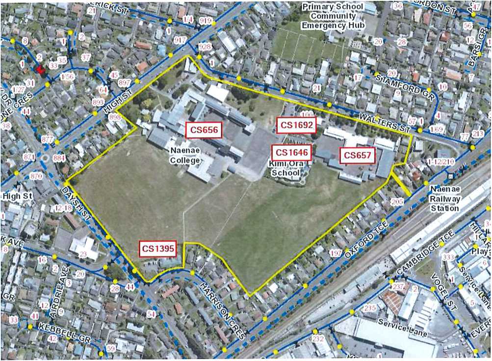
Final exit doors at locations C. D & G are to be provided with electric mortice locks for security. Under normal operation these require a swipe card to operate. These locks are to release automatically on fire alarm activation (which includes smoke detection in inis building, and on a fire alarm elsewhere in the school which requires evacuation cl the school). They arc also lo be fail-safci'fail-opon, ano be provided with an omorgoncy release button behind a frangible panel.
BC120716
|
LEGEND DEOP TOP | |
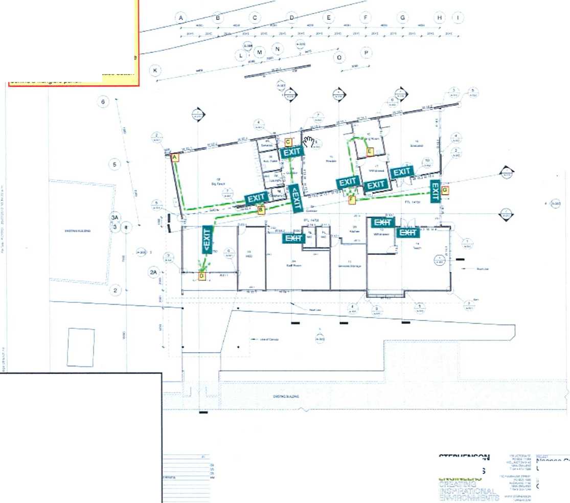
exi r EXIT EXIT |
Ground Floor Plan Suggested exit s<gn location farrows as appropriate) A-B E-F A-B-C A-B-D E-F-G |

|
'ravel route |  |
Maximum Travel Distances
15m < 10m OK
10m < 18m OK
25m < 45m OK
26m < 45m OK
22m < 45m OK
AMENDMENT
GRANTED
8/06/2013
HUTT CITY COUNCIL
HUTJ^TY
|
• Drawing Tula |
Egress Provisions | |
|
• Project: |
Naonae Special Needs Unit | |
|
• Dato 27/5/13 |
• Project No: |
9944 |
|
• Scale NTS |
• Drg No |
FSK11 |
|
• Rev: C |
• Issued |
Consent |
|
• Drawn: Joanna Williams ^^^ Wi/C*** |
s &T | |
STEPHENSON ^TURNER ARCHITECTS
Naenae College Special Needs Unit
9944
A-22O
E
LEGEND
Sprinkler Va Ve
Manual Call Point
Fire Safely Precaution* to be provided: a type 7 fire alarm system throughout - oomprising a sprinkler protection system complying with NZS4541 as modified by Appendix D of C/ASt and a manual fire alarm system complying with NZS 4512.
Extent of sprinkler protection:
Fire extinguishers or nose reels are not required for compliance with the building code, but may be recommended by the NZ Fira Service as part of the evacuation scheme approval. These should be located in areas under leecher supervision.
Fire separations
90/90/99 Fire Rating -.-.
tire
from adjacent trading
1h«i 13b from Iw tic* # Mluttnq. Hit nt*
DreMng TC® Fire Safety Precautions
Protect:
Naanae Special Needs Unit
Date 31/7/12
Protect No: 9944
Scale MTS
Or® No.: FSK21
Rev. B
tawed: Tender/Conaent
Drawn. Joanna Williams
wi4iu^f
Naonac CoSogo Spocml Needs Unit
ENGINEERS
CREAHNG [i<5P1ROTOMAL
Ground Floor Ann
EWVWMWBMW
9944
A-220
—— (60)/60/60 rRR walla with -/60/306m doora — (90)00/30 rRR walls with -/30/303m doors •—• New lift enclosure

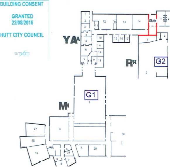
|
Proposed Now Lift Location |
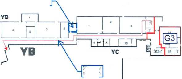 |
|
77 m total pp^n path |
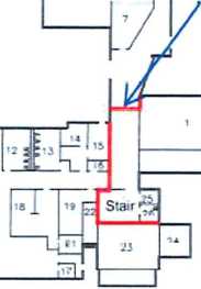
New door to bo installed

G5 |
|
CARPARKS |

21422 Naenaa ColiEoe Lift Installation
BdkSing Consent
FIRE ENGINEERING DESIGN
oaoe 15
—— (60)/60/60 FRR walls with -/60/30Sm doors
BUILDING CONSENT
GRANTED 22/08'2016
HUTT COY COUNCIL
HJl/!'!
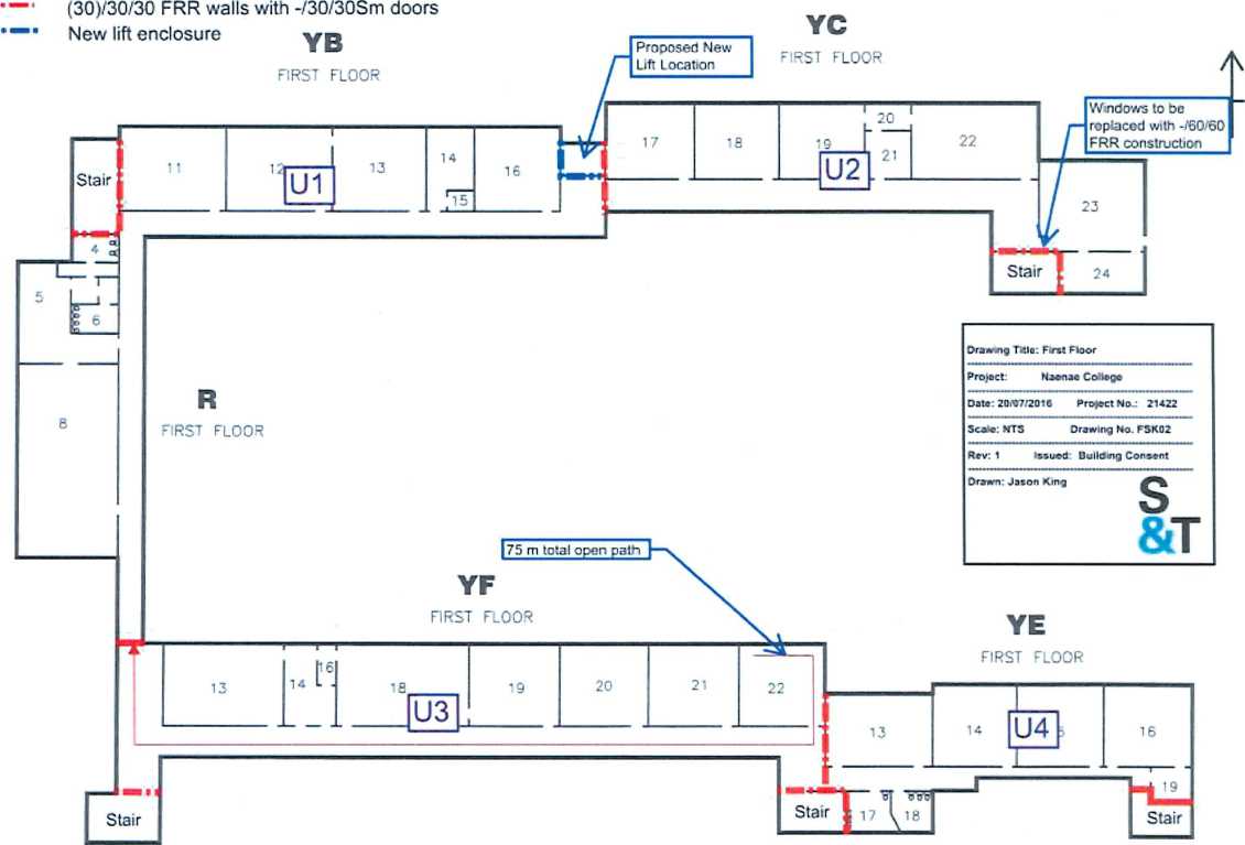
21422 Naenae College Lift Installation Bui e ng Consent
FIRE ENGINEERING DESIGN
page 16
Those documents must be retained on site. Inspections may not be carried out If they are not. ____________________]
BUILDING CONSENT
BC1T0709
GRANTED
4110/2017
HUTT CITY COUNCIL wrv<r»
From the rear of admin block
A214
Ministry of Education
Naenae College Must Slock 930 High St Avalon. Lower Hutt
Dead end path length = 11 m
Total open path length = 24 m
'87513
iq m.
Proposed Floor Plan *
Accessibility Report
Dead end path length = 2 m Total open path length = 33 m
98.6 sq m
■ ■!■■■■■■■
From main block to cafeteria and then to the hall
P0Boi3S3«
Wellington MaC Centre 51X5
New Zealand
PH *64-4-920 0032
FAX *64-4-920 0031
designgroup5t3pLatoneLUott.cr_.hr
Two accessible routes
Dead end path length = 20 m Total open path length = 42 m
REVISED 13/9/2017 ..........................~.........
HUTT CITY Propocod Root Plan for AooeccIiNllty
COUNCI©^^------
^ Dead End Open Path ^ Total Open Path
Required illuminated exit sign in accordance with F8/AS1
Required e^Staency lighting coveraq to F6/AS1
cl uslgng rc-up stapleton elliott
STEPHENSON &TURNER ENGINEERS
FIRE ENGINEERING DESIGN
for
ADMIN BLOCK
NAENAE COLLEGE 910 HIGH STREET
AVALON
LOWER HUTT
for
NAENAE COLLEGE BOARD OF TRUSTEES
Stephenson & Turner New Zealand Limited Architects and Building Services Engineers
PO Box 11393 Wellington
For Consent
July 2021
24523
CONTENTS
Document Control
Prepared by:
|
Reviewed by: |
 |
|
J. King BE, DipEngFire, CPEng |

A. Fiton
MSc (Fire Engineering), MEngNZ
|
Table 1 – Quality Assurance | ||||||
|
This is the Fire Engineering Design for the proposed alterations of the Admin Block at Naenae College at 910 High Street, Avalon, Lower Hutt. The design demonstrates compliance with the performance requirements of the New Zealand Building Code that relate to fire safety, to the extent required by the Building Act 2004.
The building is a two storey building containing classrooms, school hall, music department, cafeteria, administration area and library, and associated spaces.
-
2.2 Proposed Work
It is proposed to alter the layout of the administration area. The proposed layout is shown on the attached sketches.
The proposed alterations do not constitute a change of use.
-
2.3 Previous Work
A fire engineering design for the building was documented in “Fire Engineering Design”, dated August 2016 by Stephenson & Turner Ltd. The report used the now superseded New Zealand Acceptable Solution C/AS4 as the basis for identifying the fire safety requirements for the building. The previous fire design is attached in Section 8.3 of this report.
-
2.4 Escape Height
The building has an escape height of less than 4m.
The proposed work is an alteration to an existing building and therefore the fire engineering design of the building is to demonstrate compliance with the requirements of Sections 17 and 112 of the Building Act 2004:
17 All building work must comply with building code
All building work must comply with the building code to the extent required by this Act, whether or not a building consent is required in respect of that building work.
112 Alterations to existing buildings
-
(1) A building consent authority must not grant a building consent for the alteration of an existing building, or part of an existing building, unless the building consent authority is satisfied that, after the alteration,—
-
(a) The building will comply, as nearly as is reasonably practicable, with the
provisions of the building code that relate to—
-
(i) Means of escape from fire; and
-
(ii) Access and facilities for persons with disabilities (if this is a requirement in terms of Section 118); and
-
(b) The building will,—
-
(i) If it complied with the other provisions of the building code immediately
before the building work began, continue to comply with those provisions; or
-
(ii) If it did not comply with the other provisions of the building code immediately before the building work began, continue to comply at least to the same extent as it did then comply.
This design does not address sanitary facilities, structural performance or access, and facilities for persons with disabilities beyond any specific allowances for additional provisions identified in the egress design.
This design addresses the requirements within the building only, up to the point where escape routes reach the final exit.
The building is assessed as risk group CA (C/AS2 Table 1.1). This design uses Acceptable Solution C/AS2 Amendment 2 2020 to determine the requirements for full compliance with the New Zealand Building Code. This design includes “as nearly as is reasonably practicable” analysis to determine compliance to the extent required by the Building Act 2004.
This design also follows the “Fire and safety design requirements for schools” dated July 2008 and additional requirements from the “Addendum to Fire and Safety Design Requirements for Schools”, dated May 2018 by the Ministry of Education (MoE), which are taken into account where more stringent than the Building Code requirements. It is noted that these requirements are at the discretion of the Ministry to enforce.
The New Zealand Building Act 2004 and compliance with the Building Code address the issues of life safety, protection of neighbouring property, and allowing fire-fighting operations. They specify minimum standards for compliance and do not address the prevention or restriction of damage by fire to the subject building or its contents. Such provisions are beyond the requirements of the Act, and are matters for the owner and their insurers to address separately.
-
3.4 Fire Safety and Evacuation of Buildings Regulations
Under Section 75 of the Fire and Emergency New Zealand Act 2017, the Fire and Emergency New Zealand Regulations 2018 will apply to this building. When required, an application must be made to Fire and Emergency New Zealand for approval of an evacuation scheme.
-
3.5 Dangerous Goods
This design does not address the presence of any dangerous goods in the building. Any such goods used or stored within the building should comply with the dangerous goods regulations.
-
3.6 Assumptions
The following general assumptions have been made as part of the fire engineering design:
-
• The design of the building will comply with the Building Code.
-
• The design will comply with D1/AS1.
-
• The design will comply with the HSNO Act.
Further, in the assessment of the fire design of the building, the following assumptions are implicit:
-
• A single fire location for any scenario only is considered (multiple independent fires are not considered).
-
• Arson, or intentional involvement of accelerants is not considered.
-
• All building occupants are assumed to be generally available to evacuate unassisted, with a proportion of persons with disabilities no higher than in the general population.
-
• Building occupants are awake and alert and not incapacitated by drugs or alcohol.
-
• The occupants are assumed to be generally familiar with the layout of the building.
It is assumed that the contents of this fire report have been read, understood, and incorporated within designs by other trades or disciplines. Stephenson and Turner Ltd disclaims any responsibility for designs by other trades or disciplines.
The occupant number is taken from the referenced fire design, or from the occupant load from C/AS2 Table 1.2 for the area of alteration. The table below details the occupancy:
| |||||||||||||||||||||||||||||||||||||||||||||||||||||||||||||||||||||||||||||||
|
1 It is not expected that all areas would contain the maximum occupancy simultaneously | |||||||||||||||||||||||||||||||||||||||||||||||||||||||||||||||||||||||||||||||
-
2 As identified in the referenced fire design, the maximum number of occupants in the building is taken as 950. The building is divided into firecells as noted in Section 5.1 below. Firecells are as shown on the attached sketches.
For convenience, rooms being used intermittently such as circulation spaces, toilet facilities, storerooms, etc. are not considered in the above Table as the occupants using these rooms are counted elsewhere in the building.
The floor area of an unsprinklered firecell shall not exceed 5,000m2 (C/AS2 Table 2.1).
The Ground Floor is divided into five firecells and Level 1 is divided into four firecells. Each stair is also a separate firecell except the south west stair which is not fire separated from the Ground Floor.
Based on the referenced fire design, the existing firecells in the building are less than 5,000m2 and comply with this requirement.
Refer to Section 5.5.1 for internal fire separation requirements.
-
5.2 Fire Safety Systems
As per the referenced fire design, the building is fitted with an automatic smoke detection and manual fire alarm system throughout. The system is expected to be in compliance with NZS 4512.
Except for the firecell G3, each firecell has a maximum expected occupant load between 100 and 1000 people and the maximum escape height is less than 4m. The floor between the levels is assumed to be a fire separation, and there are no intermediate floors nor sleeping firecells in the building.
The required fire safety systems are a Type 4 automatic smoke detection and manual fire alarm system and a Type 18 building hydrant system (C/AS2 Table 2.2b).
The Type 18 building hydrant system is not required to be considered under Section 112 of the Building Act 2004.
The existing Type 4 fire safety system meets the minimum requirements. The existing fire alarm system is to be altered as necessary to suit the new layout, in accordance with NZS 4512.
Refer to Section 6.1 for the additional Ministry requirements.
-
5.3 Fire Resistance Ratings
The fire resistance ratings of internal fire separations are to be based on the life rating of 60 minutes (C/AS2 Table 2.4). Internal fire separations are addressed in Section 5.5.1 of this report.
The fire resistance ratings of external fire separations are to be based on the property rating of 120 minutes (C/AS2 Table 2.4). External fire separations are addressed in Section 5.6 of this report.
-
5.4 Means of Escape
-
5.4.1 Number of Escape Routes
Each firecell has a maximum occupancy of less than 500 people, except for firecell G3 which may contain between 500 and 1000 occupants. The required number of escape routes is as per the table below (C/AS2 Table 3.1):
Firecell
Occupancy
Required number of escape routes
Provided number of escape routes
G1
> 500 but < 1000
3
3
G2
< 500
2
2
G3
< 501
1
1
G4
< 500
2
2
G5
< 500
2
2
U1
< 500
2
2
U2
< 500
2
2
U3
< 500
2
2
U4
< 500
2
2
-
1 Firecell G3 is permitted with a single escape route because it contains less than 50 occupants, the escape height is less than 10m and has a maximum open path length less than the permitted dead-end open path length (C/AS2 3.13.1).
The number of escape routes complies with the requirement.
-
5.4.2 Height of Escape Routes
The clear height shall be no less than 2100mm across the full width except that landings, stairways and corridors (less than 2m in length) may reduce the required height by no more than 100mm. Any door opening within, or giving access to, any escape route shall have a clear height of no less than 1955 mm for the required width of the opening (C/AS2 3.3.1).
The escape route heights meet these requirements.
-
5.4.3 Length of Escape Routes
Permitted escape route lengths are given in C/AS2 Table 3.2. The permitted and measured maximum escape route lengths are as follows (taken from the referenced fire design):
Dead End Open Path
Total Open Path
| ||||||||||||||||||||
|
1 2 |
Escape route lengths are marked on the attached sketches and referenced fire design. The proposed and existing escape route lengths comply with the requirements.
-
5.4.4 Width of Escape Routes
The minimum required width for escape routes that are not accessible routes (C/AS2 3.3.2c):
-
• 850 mm for open path horizontal travel.
-
• 1000 mm for any exitway.
These can be reduced to 700mm for horizontal travel within dead end open paths.
The total required width in unsprinklered firecells shall still be available should the widest of the escape routes be unusable (C/AS2 3.3.2d) and allow 7mm/person for horizontal travel and 9mm/person for vertical travel (C/AS2 3.3.2a). Required and provided escape route widths are as follows:
|
Firecell |
Number of occupants |
Horizontal width required |
Vertical width required |
|
G1 |
782 |
5,474mm |
N/A |
|
G2 |
127 |
889mm |
N/A |
|
G3 |
10 |
70mm |
N/A |
|
G4 |
164 |
1,148mm |
N/A |
|
G5 |
99 |
693mm |
N/A |
|
U1 |
160 |
1,120mm |
1,440mm |
|
U2 |
146 |
1,022mm |
1,314mm |
|
U3 |
176 |
1,232mm |
1,584mm |
|
U4 |
100 |
700mm |
900mm |
As noted in the referenced fire design, the escape route widths comply with the above requirements.
-
5.4.5 Doors Subdividing Escape Routes
The requirements for doors on escape routes are given in C/AS2 3.15.
Doors on escape routes shall be hinged or pivoted on one vertical edge only, except that sliding doors may be used where the space has an occupant load of less than 20. The doors existing doors are expected to meet this requirement.
Door handles shall comply with D1/AS1 for use by people with disabilities.
Doors shall be constructed to ensure that the forces required to open these doors do not exceed those able to be applied:
-
• With a single hand to release the latch, and
-
• Using two hands to set the door in motion, and
-
• Using a single hand to open the door to the minimum required width.
When the building is lawfully occupied locking devices shall:
-
• Be clearly visible, located were such a device would normally be expected and, in the event of fire, designed to be easily operated without a key or other security device and
allow the door to open in the normal manner. If the pressing of a button close to the door is required, it shall have signage complying with F8/AS1, and
-
• Not prevent or override the direct operation of panic fastenings fitted to any door, and
-
• If of an electromechanical type, in the event of a power failure or door malfunction, either
o Automatically switch to the unlocked fail-safe condition, or
o Be fitted with a push button or switch that releases the lock and allows the door
to be opened from the inside (without a swipe card or key code). This push button or switch may be placed behind a break-glass panel but must be clearly labelled “Emergency door release”.
Doors on escape routes shall be hung to open in the direction of escape except if the number of occupants in the space using the door as an escape route is less than 50. The existing doors are expected to comply with this requirement.
Doors on open paths shall provide an unobstructed opening width no less than 760mm, and when multi-leaf, have no single leaf less than 500mm. The minimum width may be reduced to 600mm if the route is not required to be an accessible route. The existing door widths are expected to meet these requirements.
Within exitways (including entry and final exit doors), the minimum exitway width required is 875mm within horizontal safe paths and vertical safe paths.
Doors shall open no less than 90°, open onto a floor area which extends for a distance of no less than the arc of the door swing and is at the same level on both sides of the door for the full width of the escape route.
When opened, doors shall not cause the door swing to obstruct the minimum required width of any escape route.
The doors including the main entrance shall provide free egress in the direction of escape at all times.
Doors on escape routes (whether or not the doors are fire doors) shall be fitted with simple fastenings that can be easily operated from the direction from which people approach when making their escape (C/AS2 3.15.14).
Vision panels shall be provided on doors which are hung to swing both ways, lead into, or are within, exitways, except when the door is the egress from a sleeping space, or subdivide corridors used as escape routes (C/AS2 3.15.6).
Vision panels are assumed to have been provided where required on doors leading into exitways.
Automatic sliding doors in an open path or at final exits are permitted provided that in the event of a power failure or malfunction, the door or access control systems shall continue to provide a safe means of escape from fire without reducing the required width by either automatically opening and remaining open or being readily pushed to the outward position by the building occupants in an emergency (C/AS2 3.15.7).
The new automatic sliding door is required to be fitted with a fail-safe device to automatically slide open on any malfunction or power failure and remain open, or be readily pushed to the outward position by the building occupants in an emergency.
Panic fastening devices shall be fitted on doors on the escape route including exitways and final exits where serving more than 100 people (C/AS2 3.15.2). The panic fastening devices have been discussed in the referenced fire design and panic fastening devices are provided where required. The existing arrangement is proposed to be maintained.
-
5.4.6 Dead Ends
A dead end shall not serve an occupant load greater than 50 (C/AS2 3.8.2).
There is no dead end exceeding 50 people, which complies with the requirement.
-
5.4.7 External Escape Routes
External escape routes are required to meet the requirements of a safe path between the point where they enter a space exposed to the open air and the final exit. Safe path separation requirements shall be achieved by providing either distance or fire rated construction between the escape route and adjacent firecells (C/AS2 3.11.1).
Separation by distance shall be achieved by (C/A2 3.11.2):
-
a) If there is only one direction of escape, roofs and external walls shall not have unprotected areas closer to an external escape route than 2.0m, or
-
b) The escape route shall be located so that it diverges from external walls, or
For an escape route which passes through an opening in an external wall, parts of the external wall need not be fire rated if:
-
i. The direction of escape to a single final exit diverges from the external wall at an angle of no less than 45° in plan, or
-
ii. The directions of escape to alternative final exits diverge from each other at an angle of no less than 90° in plan and the escape routes subsequently do not both pass the same firecell (other than the firecell from which they originated).
-
c) Where alternative directions of escape are provided from the point where the escape route passes through an external wall and becomes an external escape route, unprotected areas are permitted.
In the area of alteration, the external deck provides a direction of escape to a single final exit that diverges from the external wall at an angle of no less than 45° in plan (C/AS2 3.11bii).
All other external escape routes are not to be altered as part of the proposed work and are expected to comply with the above requirements.
-
5.4.8 Signs
All building features shall have signs complying with F8/AS1 (C/AS2 3.16.1).
As noted in the referenced fire design, a progressive upgrade process is underway whereby all signs will be self-illuminated signs.
As part of this project it is proposed that all signs within the area of alteration be upgraded as required to self-illuminated signs, in compliance with F8/AS1. The recommended locations of exit signs are shown on the attached sketches.
-
5.4.9 Visibility in Escape Routes
Emergency lighting is required to be provided throughout the building to comply with F6/AS1. The existing building is fitted with a partial coverage emergency lighting system.
The referenced fire design used an ANARP analysis to determine compliance with the requirements that relate to emergency lighting to the extent required by Section 112 of the Building Act 2004. Given that the proposed work is that of a similar nature to the referenced fire design, the ANARP analysis is considered to remain valid. Therefore, emergency lighting is not required to be upgraded throughout the building. Refer to Appendix 8.3.
It is however proposed that emergency lighting and/or photoluminescent wayfinding marking be provided in the area of alteration, including the new external decks, ramps and stairs, to comply with F6/AS1.
Each floor in a multi-storey building shall a fire separation (C/AS2 4.31.1). Floors shall have an FRR for exposure from the underside and achieve 60/60/60 FRR (C/AS2 4.13.2).
The floor is of concrete construction and expected to achieve the required 60/60/60 FRR.
-
5.5.1.2 Safe Path Stairwells
The safe path stairwells shall be separated from all adjoining firecells by fire separations achieving (60)/60/60 FRR (C/AS2 4.9.2).
The referenced fire design used an ANARP analysis to determine compliance with the requirements that relate fire separations to the extent required by Section 112 of the Building Act 2004. It was determined that even though some fire separations did not achieve (60)/60/60 FRR but (30)/30/30 FRR, these were considered to comply as nearly as is reasonably practicable with the requirements. Given that the proposed work is of a similar nature to the referenced fire design, the ANARP analysis is considered to remain valid. Therefore, the existing fire separations are not required to be upgraded to achieve (60)/60/60 FRR. Refer to Appendix 8.3
Fire doors shall have a FRR of -/60/30 Sm FRR (C/AS2 4.16.1). As noted in the referenced fire design, all fire doors have been required to be maintained and returned to full operational condition, including the operation of hold open devices. The fire doors are therefore expected to comply with this requirement.
Existing fire separations are not proposed to be altered as part of the proposed work.
-
5.5.1.3 Lift
Lift, conveyors and services which pass from one firecell to another shall be enclosed within protected shafts. Every protected shaft shall be a separate firecell within the firecell or firecells in which it is located. The shaft walls between each floor shall have an FRR applied to both sides (C/AS2 4.11.1 & 4.11.2). Alternatively, shafts shall be fire separated at each floor with all service penetrations fire stopped. Protected shafts which do not extend through the roof or lowest floor shall be enclosed at their top and bottom by construction which satisfies the required fire resistance rating (C/AS2 4.11.3).
As identified in the referenced fire design, the lift shaft is expected to achieve the required (60)/60/60 FRR.
Lift landings shall not open into or be located between open paths and shall be provided with a smoke lobby separated from all other areas (C/AS2 3.10.4).
For full compliance, smoke lobbies should be retrofitted at each lift landing throughout the building.
The benefits associated with providing smoke lobbies is to prevent smoke spreading through the lift shaft between levels. It is noted that the smoke would be required to spread into the lift shaft through the lift door, upwards to fill up the lift shaft until being able to spread out from the lift shaft through the lift door on the upper level. For that scenario to occur it is considered that a reasonable amount of time would be required, where in contrast to the early warning provided by the fire alarm system, it is considered very unlikely that any egressing occupants
be impeded by smoke, especially when considered that alternative escape routes are provided.
The sacrifices associated with such upgrade include the cost and work involved to provide the smoke lobbies, as these are also remote from the area of alteration.
Given the above, it is not considered that the benefits associated with retrofitting smoke lobbies outweigh their associated sacrifices. Therefore, the lift landings are considered to comply as nearly as is reasonably practicable.
There are no additional fire and smoke separation requirements within the building for full compliance. Refer to the attached sketches for the location and required fire resistance ratings of internal fire separations.
Refer to Section 6.2.1 for the additional Ministry requirements.
Any structural elements providing structural support to fire rated construction shall either have the same FRR for stability as the supported element, or be in another firecell from the supported element.
Any element connected to a fire rated element shall either have the same FRR for stability as the connected element, or shall have connections designed to collapse without affecting the stability of the fire rated element.
Structural elements shall comply with Section B1 of the Building Code, including post-fire stability requirements.
-
5.5.3 Service Penetrations through Fire Separations
Any service penetrations through fire separations are to be fire sealed with suitably tested fire stopping systems to maintain the same fire resistance rating as the separation (C/AS2 4.4.2).
Any new service penetrations through fire separations are to be fire sealed with suitably tested fire stopping systems to maintain the fire resistance rating of the penetrated element.
Existing surface finishes are expected to have complied with the requirements at the time of construction and are therefore considered to comply as nearly as is reasonably practicable with the requirements.
All new surface finishes and suspended flexible fabrics shall comply with the following requirements:
|
LOCATION |
REQUIREMENTS |
|
Crowd spaces wall and ceiling linings |
Group No. 1S or 2S. |
|
Wall and ceiling linings in other occupied spaces |
Group No. 1, 2 or 3. |
|
Exitways wall and ceiling linings (stairwells) |
Group No. 1S. |
|
Ducts for HVAC systems – internal surfaces |
Group No. 1S. |
|
Ducts for HVAC systems – external surfaces |
Group No. 1, 2 or 3. |
|
Flooring |
Minimum critical radiant flux 2.2 kW/m2. |
|
Suspended flexible fabrics |
Flammability index not greater than 12. |
If foamed plastics building materials or combustible insulating materials form part of a wall or ceiling system, the complete system shall achieve a Group Number as specified above and the foamed plastics shall comply with the flame propagation criteria as specified in AS 1366 for the material being used. Foamed plastics shall not be used to comply with the Ministry requirements.
-
5.6 Control of External Fire Spread
External fire spread is not required to be considered under Section 112 of the Building Act 2004.
-
5.7 Fire Service Access and Firefighting Facilities
Firefighting facilities are not required to be considered under Section 112 of the Building Act 2004.
The Ministry of Education requirements are separate requirements and generally additional to the requirements of the Building Act, therefore all of these requirements must be met unless advised otherwise by the Ministry of Education.
The fire alarm system requirements (as per latest addendum) are as follows:
-
1 The minimum fire alarm system type shall be a Type 4 (i.e. an automatic fire alarm system activated by smoke detectors and manual call points). In areas that are prone to false alarms for smoke detectors, heat detectors can be used instead of smoke detectors, and a Type 3 system with supplementary smoke detectors is allowed. This fire alarm system requirement is not applicable to ancillary buildings and outbuildings - except boiler rooms, plant rooms, or buildings that are vital for the operation of the school.
-
2 In all new buildings or existing buildings being substantially altered or redeveloped which provide permanent sleeping accommodation, a minimum Type 5 fire alarm system shall be provided.
-
3 Direct FENZ connection is mandatory in all cases.
-
4 The fire alarm systems must be:
-
• Site wide integrated with a single point of access for monitoring and control,
-
• Analogue addressable,
-
• Of spare capacity to accommodate predicated growth (20% spare board capacity for expansion), and
-
• Integrated into a mimic alarm panel located at an appropriate place for ease of access by FENZ emergency response personnel upon arrival at site.
The existing Type 4 fire safety system is integrated in a site wide fire alarm system and meets the above requirements. The existing fire alarm system is to be altered as necessary to suit the new layout, in accordance with NZS 4512.
Areas in the building shall be subdivided to create firecells comprising a maximum of 800m2 in area. The building is currently subdivided into nine firecells, however some appear to exceed 800m2. Therefore, supplementary fire separations should be retrofitted to reduce the firecell sizes to less than 800m2. This requirement is at the Ministry’s discretion to enforce.
New fire separations, if provided, are to achieve (60)/60/60 FRR with -/60/30 Sm FRR fire doors and are to extend to the underside of the roofing and inside face of the cladding material.
-
6.2.2 External Fire Spread
External fire spread between buildings on the same property must be considered for compliance with the Ministry requirements.
However, given that the building is existing and that the proposed alterations do not impact on the separation distance requirements, external fire spread between buildings on the same property is not required to be considered further.
Rooms with up to 20 occupants are to have at least one door at least 810 mm wide, opening in either direction. Manual sliding doors are considered to be at least equivalent to inward opening doors and are therefore also permitted.
Rooms with more than 20 occupants are to have at least one door at least 810 mm wide opening outwards.
Rooms with more than 50 occupants are to have at least two doors at least 810 mm wide, opening outwards.
All other escape route features are to comply with Acceptable Solution requirements.
The proposed door widths and opening directions in the area of alteration meet the requirements. It is not proposed that the other door widths and opening directions throughout the building be reviewed as part of this report.
The surface finish requirements relate to superseded versions of the Acceptable Solutions. It is considered that compliance with current requirements will meet the Ministry of Education requirements.
Foamed plastics building materials are not to be used.
FENZ vehicle standing areas are to be provided at no more than 18m from any part of the building to be protected.
The maximum hose run to the most distant point of buildings from the vehicle access position should not be more than 75m.
Fire service vehicular access is provided from High Street and Walters Street across the school site. The hose run distance from any hard standing to any part of the building is expected to be less than 75m.
The school must have an evacuation procedure. The evacuation procedure needs to be approved by Fire and Emergency New Zealand.
The evacuation procedure should include:
-
1. Procedures for safe, expeditious and efficient evacuation.
-
2. Appointment and training of wardens.
-
3. Management of escape routes.
-
4. Special provision for avoidance of panic.
-
5. Identification of wardens.
-
6. Display of notices explaining procedures.
-
7. Holding of trial evacuations.
-
8. Assembly points and evacuation points.
-
9. Special provision for the evacuation of people with disabilities.
-
10. Proposed evacuation points and time to be taken to evacuate to, between and from those points to a predetermined assembly point or assembly points.
Provided the building is altered as shown on the attached sketches and in accordance with the following requirements it will meet the fire safety requirements of the New Zealand Building Code to the extent required by the Building Act 2004.
-
• The existing Type 4 fire safety system is to be altered as necessary to suit the new layout, in accordance with NZS 4512.
-
• Doors on escape routes are to comply with the requirements identified in Section 5.4.5 of this report.
-
• All exit signs within the area of alteration are to be upgraded as required to self-illuminated signs, in compliance with F8/AS1. The recommended locations of exit signs are shown on the attached sketches.
-
• Emergency lighting is to be provided in the area of alteration, including new external decks, ramps and stairs, to comply with F6/AS1.
-
• The new automatic sliding door is required to be fitted with a fail-safe device to automatically slide open on any malfunction or power failure and remain open, or be readily pushed to the outward position by the building occupants in an emergency.
-
• Any new service penetrations through fire separations are to be fire sealed with suitably tested fire stopping systems to maintain the fire resistance rating of the penetrated element.
-
• Any structural elements connected to or providing structural support to fire rated construction shall comply with the requirements identified in Section 5.5.2 of this report.
-
• Any new surface finishes, suspended flexible fabrics and foamed plastics building materials are to comply with the requirements identified in Section 5.5.4 of this report.
-
• Supplementary fire separations should be retrofitted within the building to reduce the firecell sizes to less than 800m2. This requirement is strictly at the Ministry’s discretion to enforce.
If provided, new fire separations would be required to achieve (60)/60/60 FRR with -/60/30 Sm FRR fire doors and to extend to the underside of the roofing and inside face of the cladding material. Refer to Section 6.2.1.
|
The following specified systems are expected to be required to be identified on the Compliance Schedule for the building. Refer to the MBIE Compliance Schedule Handbook for more information.
|
| ||||||||||||||||||||||||||||||||||||||||||||||||||||||||||||||||||||||||||||||||||||||||||||
|
Specified System |
Existing, new, or altered |
Performance Standard |
Inspection & Maintenance Procedures |
|
SS14/2: Signs |
Altered |
F8/AS1 Amendment 4 January 2017 |
By owner/occupier: Monthly: Ensure signs are in place where required, are legible, clean, and illuminated By IQP: Yearly: As per monthly |
|
SS15/1: Systems for communicating spoken information intended to facilitate evacuation |
N/A |
NZS 4512 |
Inspection and maintenance procedures as per Section 6 of the referenced performance standard |
|
SS15/2: Final exits |
Existing and new |
C/AS2 Amendment 2 November 2020 3.1 & 3.12 |
By owner/occupier: Daily: Check doors are not locked, blocked, or barred Weekly: As per daily, plus ensure routes to final exits do not contain combustibles, that doors are fitted with simple fastenings, and that they swing to full width of opening By IQP: Yearly: As above |
|
SS15/3: Fire separations |
Existing |
C/AS2 Amendment 2 November 2020 Part 4 |
By owner/occupier: Weekly: Check for damage to separations, operation of fire doorsets and any locking devices By IQP: Yearly: As above |
|
SS15/4: Signs |
Altered |
F8/AS1 Amendment 4 January 2017 |
By owner/occupier: Monthly: Ensure signs are in place where required, are legible, clean, and illuminated By IQP: Yearly: As per monthly |
|
SS15/5: Smoke separations |
New |
C/AS2 Amendment 2 November 2020 Part 4 |
By owner/occupier: Weekly: Check for damage to separations, operation of smoke doorsets and any locking devices By IQP: Yearly: As above |
|
SS16: Cable cars |
N/A |
As required by the Specialist Designer |
As required by the Specialist Designer |
FSK 01 – Ground Floor
FSK 02 – Level 1
FSK 03 – Proposed Fitout
FSK 01 – Ground Floor
. (60)/60/60 FRR walls with -/60/30Sm doors (as per referenced fire design) , (30)/30/30 FRR walls with -/30/30Sm doors (as per referenced
|
Drawing Title: Ground Floor | |
|
Project: Naenae College - Admin | |
|
Project No: 24523 |
Drawing No: FSK01 |
|
Drawn: Alex Flton |
Revision: 0 |
|
Date: 28/07/2021 |
STEPHENSON &TURNER ENGINEERING |
|
Issue: For Consent | |
|
Existing Lift Location |
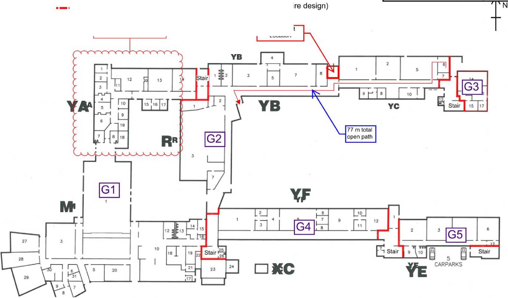 |
Proposed fitout. Refer FSK 03.
FSK 02 – Level 1
(60J/60/60 FRR walls with -/60/30Sm doors (as per referenced fire design)
(30)/30/30 FRR walls with -/30/30Sm doors (as per referenced fire design)
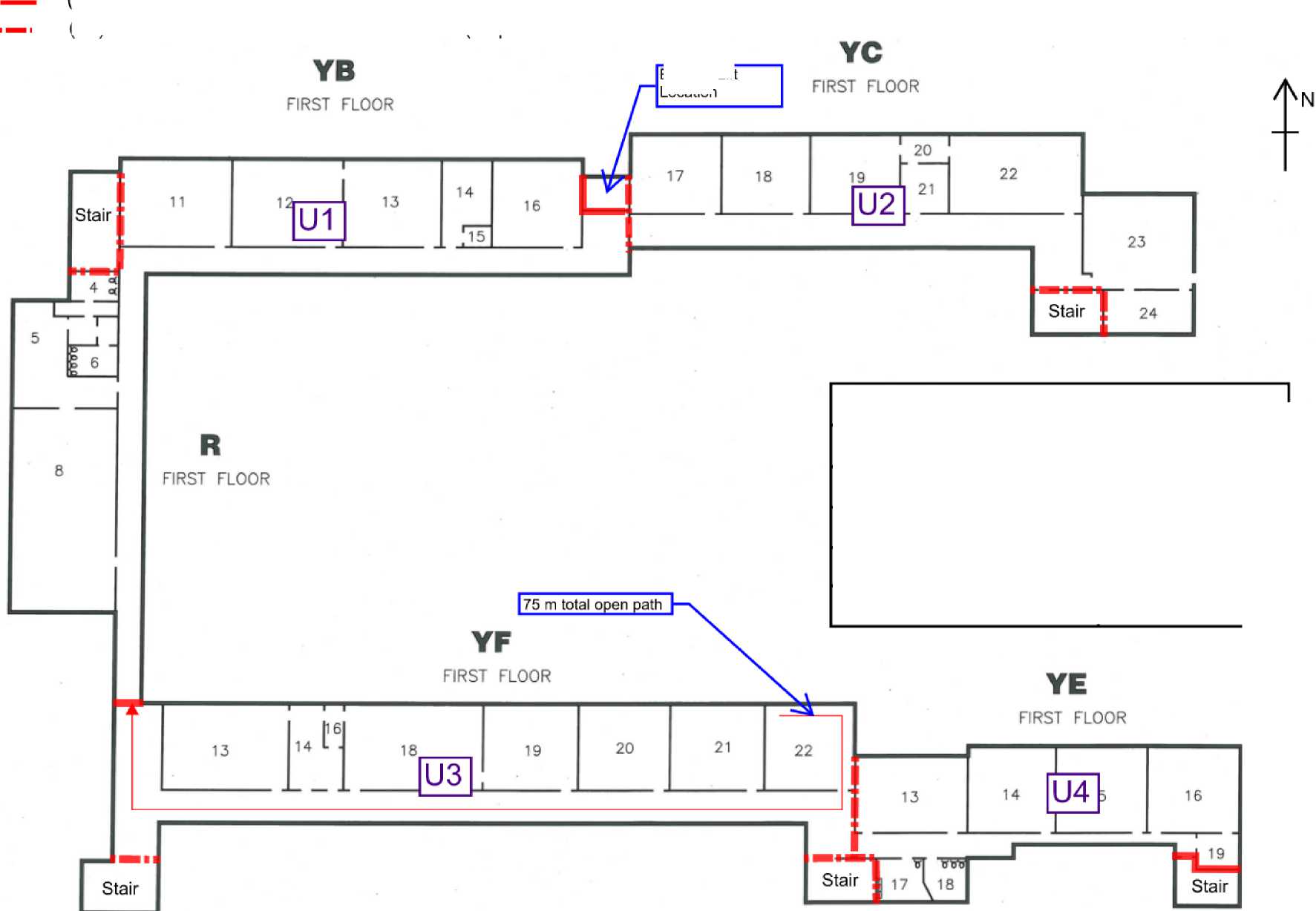
Existing Lift
Location
|
Drawing Title: Level 1 | |
|
Project: Naenae College - Admin | |
|
Project No: 24523 |
Drawing No: FSK02 |
|
Drawn: Alex Flton |
Revision: 0 |
|
Date: 28/07/2021 |
STEPHENSON &TURNER ENGINEERING |
|
Issue: For Consent | |
FSK 03 – Proposed Fitout
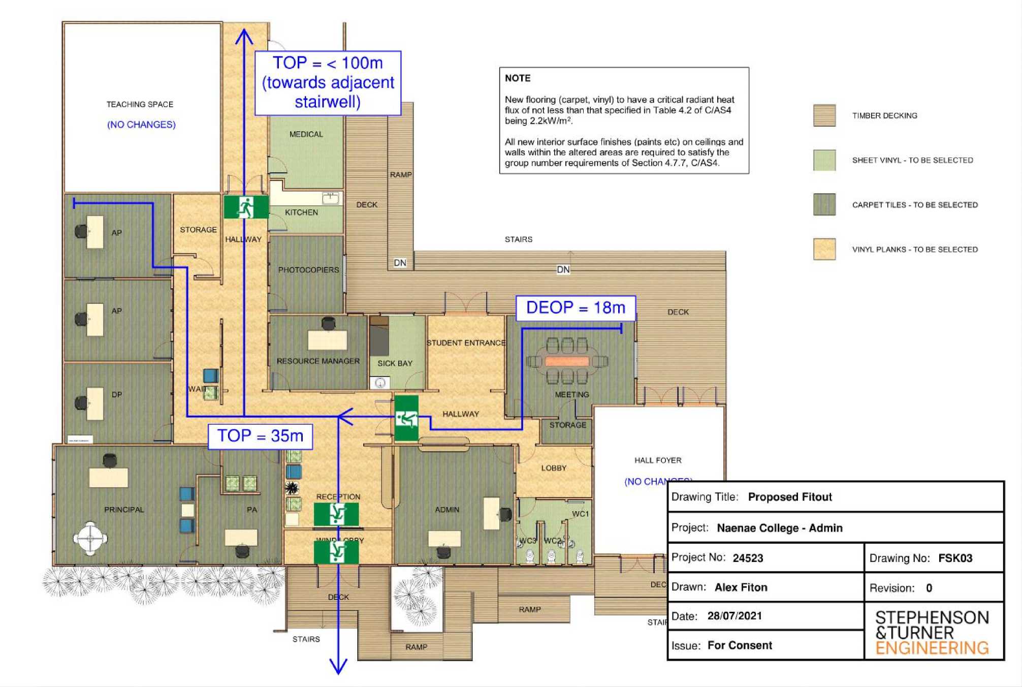
PHOTOCOPIERS DEOP DECK iTUDENT ENTRANCE RESOURCE MANAGER SICK BAY MEETING HALLWAY STORAGE HALL FOYER LOBBY RECE ’TlON PRINCIPAL ADMIN WC1 RAMP STAIRS RAMP TIMBER DECKING SHEET VINYL - TO BE SELECTED CARPET TILES - TO BE SELECTED VINYL PLANKS - TO BE SELECTED TEACHING SPACE (NO CHANGES) MEDICAL STORAGE HALl WAY DECK RAMP STAIRS KITCHEN NOTE New flooring (carpet, vinyl) to have a critical radiant heat flux of not less than that specified in Table 4.2 of C/AS4 being 2.2kW/m2. All new interior surface finishes (paints etc) on ceilings and walls within the altered areas are required to satisfy the group number requirements of Section 4.7.7, C/AS4. TOP = < 100m (towards adjacent stairwell) |
|
Drawing Title: Proposed Fitout | |
|
Project: Naenae College - Admin | |
|
Project No: 24523 |
Drawing No: FSK03 |
|
Drawn: Alex Fiton |
Revision: 0 |
|
Date: 28/07/2021 |
STEPHENSON &TURNER ENGI |
|
Issue: For Consent | |
STEPHENSON
^TURNER
ARCHITECTS
ENGINEERS
FIRE ENGINEERING DESIGN
for
NEW LIFT INSTALLATION
NAENAE COLLEGE 910 HIGH ST LOWERHUTT
for
NAENAE COLLEGE
Stephenson & Turner New Zealand Limited Architects and Building Services Engineers PO Box 11393 Wellington
BUILDING CONSENT ISSUE 3
August 2016
21422
CONTENTS
Appendix A - MBIE Score Sheet 18
Document Control
Prepared by
BE, DipEngFire, CPEng
Revision history
21/12/15 Building Consent
20/07/16 Building Consent Issue1
16/08/16 Building Consent Issue2
18/08/16 Building Consent Issue3
This is the Fire Engineering Design for the proposed alterations for a new lift installation to the main building at Naenae College, 910 High St, Lower Hutt. The design demonstrates compliance with the performance requirements of the New Zealand Building Code that relate to fire safety, to the extent required by the Building Act 2004.
The main building is a two storey building containing classrooms, school hall, music department, cafeteria, administration area and library, and associated spaces.
It is proposed to install a lift in an existing atrium at the north side of the building.
The use of the building will remain unchanged from its current use.
For the purposes of this report north is taken to be as shown on the attached sketches.
The building has an escape height <4 m.
The proposed work is an alteration without change of use and Section 112 of the Building Act applies.
112 Alterations to existing buildings
-
(1) A building consent authority must not grant a building consent for the alteration of an
existing building, or part of an existing building, unless the building consent authority is satisfied that, after the alteration, the building will –
-
(a) comply, as nearly as is reasonably practicable, with the provisions of the building code that relate to –
-
(i) means of escape from fire; and
-
(ii) access and facilities for persons with disabilities (if this is a requirement in terms of section 118); and
-
(b) continue to comply with the other provisions of the building code to at least the same extent as before the alteration.
This design does not address sanitary facilities, structural performance or access and facilities for persons with disabilities beyond any specific allowances for additional provisions identified in the egress design.
The occupancy of the building is assessed as Risk Group CA (C/AS4 Table 1.1).
Ministry of Building, Innovation and Employment (MBIE) guidelines are used to determine the extent of information to be provided in relation to the proposed alterations. These guidelines use a scoring system to determine the level of information required to be provided in relation to proposed works to the building. The score sheet for this building is included in Appendix A to this report.
The calculated score for this building is 17 For a building with a score between 12 and 19 the recommended information to be provided is:
12-19 Gap assessment using the appropriate Acceptable Solution from C/ASi - C/AS?
It is reasonable to request a gap assessment of the existing building's means of escape from fire unless the individual circumstances of the building suggest otherwise.
The gap assessment should:
■ use the appropriate Acceptable Solution from C/AS1 - C/AS7 • highlight where the existing building fully complies with the Acceptable Solution
• highlight where there are gaps between the building's fire systems and features and the requirements of the Acceptable Solution
-
• for each gap, assess whether ANARP is achieved and give options to improve the compliance in this respect
-
• cover the entire building.
A gap assessment using an Acceptable Solution can be undertaken for complex, existing buildings even if they have features that do not comply with the Acceptable Solution. For example, a building may have more than one intermediate floor or one floor that is larger than permitted in the Acceptable Solution. In this case, the gap assessment should highlight where the existing building complies with the appropriate Acceptable Solution and where there is any gap.
This design uses Acceptable Solution C/AS4 as the basis for determining what would be required for full compliance with the New Zealand Building Code and notes where compliance is not achieved. An analysis of compliance as nearly as is reasonably practicable (ANARP) is presented in Section 7 of this report.
The New Zealand Building Act 2004 and the Building Code address the issues of life safety, protection of neighbouring property, and allowing fire-fighting operations. They specify minimum standards for compliance and do not address the prevention or restriction of damage by fire to the subject building or its contents. Such provisions are beyond the requirements of the Act, and are matters for the owner and their insurers to address separately.
Under section 21A of the Fire Service Act, the Fire Safety & Evacuation of Buildings Regulations will apply to this building. When required, an application must be made to the NZ Fire Service for approval of an evacuation scheme. Although the fire safety precautions contained within this design should allow the approval of the scheme, we recommend that the Fire Service be consulted prior to occupation of the altered building.
This design does not address the presence of any dangerous goods in the building. Any such goods used or stored within the building should comply with the dangerous goods regulations.
For the assessment of the fire design of the building, the following assumptions are implicit:
-
• A single fire location for any scenario only is considered (multiple independent fires are not considered).
-
• Arson, or intentional involvement of accelerants is not considered.
-
• All building occupants are assumed to be generally available to evacuate unassisted, with a proportion of persons with disabilities no higher than in the general population.
-
• Building occupants are awake and alert and not under the influence of drugs or alcohol.
-
• The occupants are assumed to be generally familiar with the layout of the building.
The client has provided a copy of a fire engineering design for this building prepared by National Consultants Ltd, entitled “Fire Safety Assessment Report Number 10740”, dated 4 March 2016, relating to an upgrade to the fire alarm system to a Type 4 smoke detection and alarm system throughout the building.
As identified in the referenced previous report, the maximum number of occupants in the building is taken as 950. The building is divided into firecells as noted in Section 6.1 below. Firecell numbers are as shown on the sketches attached to this report.
|
The approximate maximum number of occupants for each space is as follows: | ||||||||||||||||||||||||||||||||||||||||||||||||||||||||||||||||||||||||||
| ||||||||||||||||||||||||||||||||||||||||||||||||||||||||||||||||||||||||||
|
Notes: 1. Circulation spaces are excluded to avoid duplication. 2. Occupant densities are taken from C/AS4 Table 1.2. 3. It is not expected that all areas would contain the maximum occupancy simultaneously. |
Awareness - The occupants are assumed to be awake and fully aware of the activities in their surroundings.
Familiarity - The occupants are assumed to be familiar with the layout of the building.
As the building is not sprinklered the firecell area is limited to a maximum of 5,000 m2 (C/AS4 2.1.1).
Based on the locations of fire doors as observed on site, and assuming that the fire doors are installed in fire separation walls, the ground floor is divided into five firecells and the first floor is divided into four firecells. Each stair is also a separate firecell except the south west stair which is not fire separated from the ground floor.
None of the firecells exceeds 5,000 m2 floor area.
Except for the firecell G3, each firecell has a maximum expected occupant load between 100 and 1000 people and the maximum escape height is <4 m. The floor between levels is assumed to be a fire separation, there are no intermediate floors and there are no sleeping firecells in the building.
The required fire safety systems are a Type 4 alarm system, Type 9 smoke control in air handling systems and Type 18 building fire hydrant system (C/AS4 2.2.1). The fire hydrant system is not required where the Fire Service hose run distance is less than 75 m.
The existing fire safety systems meet these requirements. The smoke detection system is to be modified as necessary to meet the coverage requirements of NZS 4512 in the altered area.
The required number of escape routes from each firecell is determined from C/AS4 Table 3.1. The requirements for single escape routes are given in C/AS4 3.13.
The firecell containing the hall, performing arts area, cafeteria and administration could potentially contain between 500 and 1000 occupants and requires at least three escape routes. At least three escape routes are provided.
All other firecells except the north east ground floor firecell contain between 50 and 500 occupants and require at least two escape routes. All are provided with at least two escape routes.
The north east ground floor firecell is permitted a single escape route because it contains less than 50 occupants, has an escape height less than 10 m and has an open path length less than the permitted dead end open path length.
-
6.3.2 Height of Escape Routes
The clear height shall be no less than 2100 mm across the full width of each escape route, except that isolated ceiling fittings not exceeding 200 mm in diameter may project downwards to reduce this clearance by no more than 100 mm. Any door opening within any escape route shall have a clear height of no less than 1955 mm for the required width of the opening (C/AS4 3.3.1).
The existing escape routes meet these requirements.
-
6.3.3 Width of Escape Routes
The total combined width of all available escape routes must be sufficient to accommodate all occupants at a width per occupant of 7 mm for horizontal travel, 9 m per person for vertical travel. As the building is not sprinklered the widest escape route from each firecell is considered to be unavailable.
Required minimum total width for each firecell is as follows:
|
FIRECELL |
NO. OCCUPANTS |
HORIZONTAL WIDTH REQUIRED* |
VERTICAL WIDTH REQUIRED** |
|
G1 |
782 |
5474 mm |
NA |
|
G2 |
127 |
889 mm |
NA |
|
G3 |
10 |
70 mm |
NA |
|
G4 |
164 |
1148 mm |
NA |
|
G5 |
99 |
693 mm |
NA |
|
U1 |
160 |
1120 mm |
1440 mm |
|
U2 |
146 |
1022 mm |
1314 mm |
|
U3 |
176 |
1232 mm |
1584 mm |
|
U4 |
100 |
700 mm |
900 mm |
* The minimum permitted width for horizontal travel is 850 mm in an open path, 1000 mm is an exitway, or 1200 mm on an accessible route.
** The minimum permitted width for vertical travel is 1000 mm in an open path or exitway, 1100 mm on an accessible route.
Widths of escape routes are discussed in Section 7.2 of this report.
-
6.3.4 Length of Escape Routes
Permitted escape route lengths are given in C/AS4 Table 3.2. The permitted escape route lengths are as follows:
|
Location |
DEOP * |
Permitted TOP ** |
|
Naenae College |
40 m |
100 m |
*
**
Dead end open path Total open path
The maximum dead end open path length is approximately 15 m, which complies with the requirement.
The maximum total open path length is approximately 77 m, which complies with the requirement.
-
6.3.5 Dead Ends
A dead end shall not serve and occupant load greater than 50 (C/AS4 3.8.1). There are no dead ends that contain more than 50 occupants.
The requirements for doors on escape routes are given in C/AS4 3.15.
The condition and operation of existing doors are discussed in Section 7.6 of this report.
Doors on escape routes shall be hinged or pivoted on one vertical edge only, except that sliding doors may be used where the space has an occupant load of less than 20.
Door handles shall comply with D1/AS1 for use by people with disabilities.
Doors shall be constructed to ensure that the forces required to open these doors do not exceed those able to be applied:
-
• With a single hand to release the latch, and
-
• Using two hands to set the door in motion, and
-
• Using a single hand to open the door to the minimum required width.
When the building is occupied locking devices shall:
-
• Be clearly visible, located were such a device would normally be expected, designed to be easily operated without a key or other security device and allow the door to open in the normal manner,
-
• Not prevent or override the direct operation of panic fastenings fitted to any door, and
-
• If of an electromechanical type, in the event of a power failure or door malfunction, either o Automatically switch to the unlocked condition, or
o Be readily opened by an alternative method.
Doors on escape routes shall be hung to open in the direction of escape except if the number of occupants in the space using the door as an escape route is less than 50.
Doors on open paths shall provide an unobstructed opening width no less than 760 mm, and when multi-leaf, have no single leaf less than 500 mm. The minimum width may be reduced to 600 mm if the route is not required to be an accessible route.
Doors within exitways (including entry and final exit doors) shall provide an unobstructed opening width no less than 875 mm.
Doors shall open no less than 90°, open onto a floor area which extends for a distance of no less than the arc of the door swing and is at the same level on both sides of the door for the full width of the escape route.
When opened, doors shall not cause the door swing to obstruct the minimum required width of any escape route.
Panic fastenings shall be fitted on doors serving crowd occupancies of more than 100 people and which are required to be secured against entry while the building is occupied. The existing doors to outside from the hall are fitted with panic fastenings. No other exit doors are fitted with panic fastenings.
Doors not fitted with panic fastenings shall have simple fastenings that can be easily operated from the direction from which people approach when making their escape.
-
6.3.7 Signs
Illuminated or photoluminescent exit signage is to be provided to comply with F8/AS1. Requirements for signage are discussed in Section 7.3 of this report.
-
6.3.8 Visibility in Escape Routes
Emergency lighting is required to be provided throughout the building to comply with F6/AS1. The existing building is fitted with a partial coverage emergency lighting system.
The fire resistance rating (FRR) of internal fire separations is to be based on the life rating of 60 minutes (C/AS4 2.3.1).
The floor between levels is required to be a fire separation (C/AS4 4.13.1). The stairwells are also required to be fire separated from all other spaces.
For full compliance the fire separations should have at least the following fire resistance ratings (FRRs):
Walls (60)/60/60
Doors -/60/30Sm
Floors 60/60/60
Structure providing support to fire rated elements is required to have at least 60/-/- FRR.
Based on the fire doors observed on site the existing fire separations are a mix of 30 and 60 minute separations. Non-fire rated windows were observed in the wall between the north east stairwell and firecell U2. The FRR of the floor between levels is unknown, however the concrete construction is expected to achieve at least 60/60/60 FRR.
The condition of the existing fire separations and a reasonably practicable level of compliance are discussed in Section 7.5 of this report.
The separations between the proposed lift shaft and the rest of the building shall provide at least (60)/60/60 FRR walls, -/60/60 Sm doors and -/60/- FRR lift landing doors.
Any new penetrations through fire separations shall be fire sealed to maintain the fire resistance rating of the penetrated element.
All new surface finishes and suspended flexible fabrics within the building shall comply with the following:
|
LOCATION |
REQUIREMENT |
|
Stairwells |
Group No. 1S |
|
Wall* and ceiling linings in classrooms |
Group No. 1S or 2S |
|
Wall and ceiling linings in other occupied spaces |
Group No. 1, 2 or 3. |
|
Ducts for HVAC systems – internal surfaces |
Group No. 1S. |
|
Ducts for HVAC systems – external surfaces |
Group No. 1, 2 or 3. |
|
Flooring in protected stairways and firecells accommodating more than 50 people |
Minimum critical radiant flux 2.2 kW/m2. |
|
Flooring in other spaces |
Minimum critical radiant flux 1.2 kW/m2 |
|
Suspended flexible fabrics |
Flammability index not greater than 12. |
* The maximum group number of the wall linings in the classrooms is permitted to be increased
to group number 3 for surfaces less than 1.2 m above floor level for ground floor spaces except in firecell G1 (C/AS4 4.17.7).
If foamed plastics building materials or combustible insulating materials form part of a wall or ceiling system, the complete system shall achieve a Group Number as specified above and the foamed plastics shall comply with the flame propagation criteria as specified in AS 1366 for the material being used.
The performance of existing surface finishes is unknown. The requirement for surface finish performance in relation to the proposed alteration is discussed in Section 7.7 of this report.
External fire spread is not required to be considered under section 112 of the Building Act 2004.
Firefighting facilities are not required to be considered under section 112 of the Building Act 2004.
As noted in Section 2.3 of this report, the building is required to meet the current requirements for means of escape “as nearly as is reasonably practicable” (ANARP).
The extent of what is reasonably practicable can be assessed by a consideration of the sacrifice required to provide compliance versus the benefit provided by compliance.
It is noted that the proposed alteration is minor in its effect on fire safety of the building and the work is confined to a small area of the building. It is therefore considered that upgrading of fire safety features should be concentrated in the vicinity of the proposed alteration, while taking into account the degree of non-compliance more remote from the alteration.
There are a number areas of possible non-compliance within the building:
-
• Escape route width
-
• Escape route length
-
• Doors on escape routes
-
• Signage
-
• Emergency lighting
-
• Fire separations
-
• Surface finish performance
All corridors and final exit doors on escape routes comply with the required minimum width for any individual door or corridor.
Internal doors within the corridors also comply with the required minimum width. Widths of doors from individual rooms have not been checked, however none appeared to be unusually narrow as observed on site. It is proposed to retain all existing doors at their existing widths.
Firecell G1 has at least nine single or double leaf doors at final exits. Although the widths of these doors have not been measured, it can reasonably be expected that the doors will provide at least the required 5474 mm minimum total width with the widest door excluded.
Within this firecell the Hall has a design occupant load of 500, requiring at least two escape routes, and at least 3500 mm escape route width with the widest escape route excluded. The Hall is provided with three double leaf doors to the east, each approximately 1500 mm wide, a double leaf and two single leaf doors to the north providing a total of approximately 3600 mm to the north, and a double leaf door approximately 1500 mm wide to the west. The stage is also provided with single leaf doors to the east and the west.
The north door counts as one escape route. Excluding this route the remaining escape routes provide approximately 6000 mm width from the main hall area.
There are also two double leaf doors to the east leading to an open courtyard. These doors are not to be marked as escape routes.
Firecell G2 has at least four double leaf doors at final exits serving this firecell. These will easily provide the required minimum width with the widest door excluded.
Firecell G3 is served by one double leaf final exit which will provide the required minimum width.
Firecell G4 has escape routes via the base of the stairwell to the east of the firecell and via a corridor and final exit in firecell G2. The final exits are double leaf doors which provide the required minimum width with the wider door excluded.
Exits from firecell G5 are via the bases of the stairwells to the east and west ends of the firecell. Any one of the final exit doors from these stairs would provide the required minimum width.
Exits from firecell U1 are via the north west stairwell or via open paths in firecells U2 or U3. It is noted that the south west stair currently forms part of the open path within firecell G4. This stair is therefore not counted as an escape route from upper floor firecells. The remaining stairs and final exits provide at least the required minimum width for horizontal and vertical travel with the widest exit excluded.
Exits from firecell U2 are via the north east stair or via the open path within firecell U1 to the north west stair. A further exit is available via the open path in firecell U3 to the stair at the east end of U3.The final exits are at least three double leaf doors. The stairs and doors provide at least the required minimum exit width with the widest route excluded.
Firecell U3 has exits via the stairwell at the east of the firecell and via the open path in firecell U1 to the north west stairwell, or to the north east stairwell via U2. Each of the stairwells leads to at least one double leaf door. These escape routes provide at least the required width for vertical and horizontal travel with the widest escape route excluded.
Exits from firecell U4 are via the south east stair or through a short section of open path in U3 to the stair at the east of U3. These stairs lead to two double leaf doors. The escape routes provide at least the required escape route width.
Based on the above the escape routes within the building and the final exits are expected to provide at least the required width for compliance with C/AS4 requirements.
Existing exit signs consist of a mix of reflective and self-illuminated signs. A progressive upgrade process is under way whereby all signs will be self-illuminated signs.
As part of this project it is proposed that all the signs on escape routes from firecells G2, U1 and U2 be upgraded as required to self-illuminated signs.
Existing fire doors are not fitted with the required signs. As part of this project it is proposed to install signs to fire doors serving firecells G2, U1 and U2.
Emergency lighting is currently fitted to the ground corridor to the west of the proposed new lift, and to the north west fire separated stairs. It is not proposed to extend the emergency lighting as part of this project.
It is noted that the proposed alterations to the building are minor and have no effect on the ability of occupants to escape.
The benefit of providing emergency lighting is that visibility is maintained in case of power failure at night. In relation to fire safety this benefit occurs only if a power failure occurs simultaneously with a fire. Given that the primary use of the building is during daytime the combination of circumstances where the emergency lighting provides any benefit is very unlikely.
It is also noted that the proposed illuminated exit signs will provide guidance to escaping occupants at night.
Given the minimal benefit and the minor nature of the proposed alteration it is not considered reasonably practicable to extend the existing emergency lighting system.
Based on the locations of fire doors, and on the assumption that the walls into which the fire doors are installed are also fire rated, the building is divided into firecells as described in Section 6.1 of this report and as shown on the attached sketches.
Given the mix of 30 and 60 minute ratings the general rating for all firecells is considered to be 30 minutes. This does not comply with the current requirement to provide separations based on a life rating of 60 minutes.
The floor between levels is of concrete and may reasonably be expected to provide at least 60/60/60 FRR.
The walls appear to be framed and plasterboard lined, or concrete and may reasonably be expected to provide at least (30)/30/30 FRR.
The new separations at the location of the proposed lift are to provide (60)/60/60 FRR.
It is noted that a new Type 4 smoke detection system has recently been installed throughout the building. This will give the earliest possible warning of any fire and thereby minimise the required egress time. It is therefore likely that the existing 30 minute based fire separations will provide adequate time for all occupants to escape safely, and the benefit of upgrading to 60 minutes is small.
There would be substantial building work involved in upgrading existing fire separations to 60 minutes. Since the benefit is minimal it is not considered reasonably practicable to upgrade existing fire separations.
One exception is the windows at the first floor beside the stairwell door of the north east stair. These windows are clearly not fire rated and are to be replaced with construction having at least -/60/60 FRR.
The existing fire doors are generally in poor condition, with closers incorrectly adjusted or missing. Many of the doors are fitted with electromagnetic hold open devices, most of which appear not to be operational.
As part of this project all fire doors are to be maintained and returned to full operational condition, including the operation of electromagnetic hold open devices.
In the separation between firecells G2 and G4 a door has been removed. This is to be replaced with a new door having at least -/60/30Sm FRR.
The requirements for panic fastenings may reasonably be considered in relation to the commentary to acceptable solutions C/AS1 – C/AS7. It is expected that the hall may be used for a crowd occupancy at night, and with the doors to outside required to be secured against entry. These doors comply with the requirement for panic fastenings.
Other final exit doors serving more than 100 occupants would not normally be secured against entry during normal daytime use. If the classroom areas are used at night the occupant number is expected to be substantially less than in daytime use and it is unlikely that any door would serve more than 100 occupants. On this basis it is not proposed to fit panic fastenings to any additional doors.
Existing surface finishes generally consist of paint on plasterboard or concrete. These would generally be expected to achieve a surface finish group No. of 1S on concrete, 2S on plasterboard (C/VM2 Table A1).
This would comply with current requirements except in stairwells. Given the low probability of a fire starting in a stairwell, and that almost the entire building has alternative escape routes available, it is considered that the benefit of upgrading the surface finishes is negligible and therefore not reasonably practicable.
21422 Naenae College Lift Installation Building Consent Issue 3
Provided the fitout alterations are constructed as described in this report and in accordance with the following requirements they will meet the fire safety requirements of the New Zealand Building Code fire safety requirements to the extent required by the Building Act 2004.
-
• The existing smoke detection system is to be modified as necessary to meet the coverage requirements of NZS 4512 in the altered area.
-
• Doors on escape routes are to comply with the requirements identified in Section 6.3.6 of this report. All existing fire doors are to be maintained and returned to full operational condition, including the operation of electromagnetic hold open devices.
-
• Self-illuminated exit signage is to be provided to comply with F8/AS1.
-
• Fire doors serving firecells G2, U1 and U2 are to be fitted with signs complying with F8/AS1.
-
• The separations between the proposed lift shaft and the rest of the building shall provide at
least (60)/60/60 FRR walls, -/60/60 Sm doors and -/60/- FRR lift landing doors.
-
• A new door is to be provided in the separation between firecells G2 and G4 having at least -/60/30Sm FRR
-
• The windows at the upper floor beside the stairwell door of the north east stair are to be replaced with construction having at least -/60/60 FRR.
-
• Any new penetrations through fire separations shall be fire sealed to maintain the fire resistance rating of the penetrated element.
-
• All new surface finishes, suspended flexible fabrics and foamed plastics building materials are to comply with the requirements identified in Section 6.4.2 of this report.
FSK 01 – Ground Floor
FSK 02 – First Floor
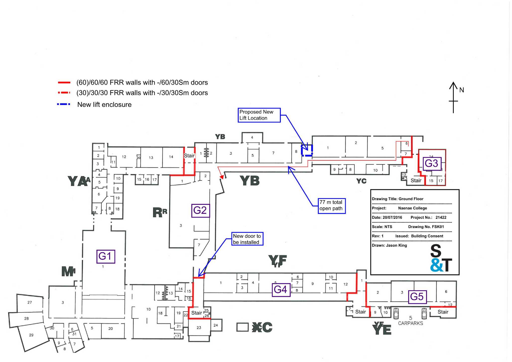
[Stairl Wō i Stair Stair — (60)/60/60 FRR walls with -/60/30Sm doors ■“• (30)/30/30 FRR walls with -/30/30Sm doors —• New lift enclosure □ MC YB Y* ~ 19 Stair ^ Drawing Title: Ground Floor Project: Naenae College Scale: NTS Drawing No. FSK01 Rev: 1 Issued: Building Consent Drawn: Jason King I 5 E CARPARKS Date: 20/07/2016 Project No.: 21422 Proposed New Lift Location 77 m total open path New door to be installed _G3 G4 h |
|
(60)/60/60 FRR walls with -/60/30Sm doors Proposed New Lift Location | |
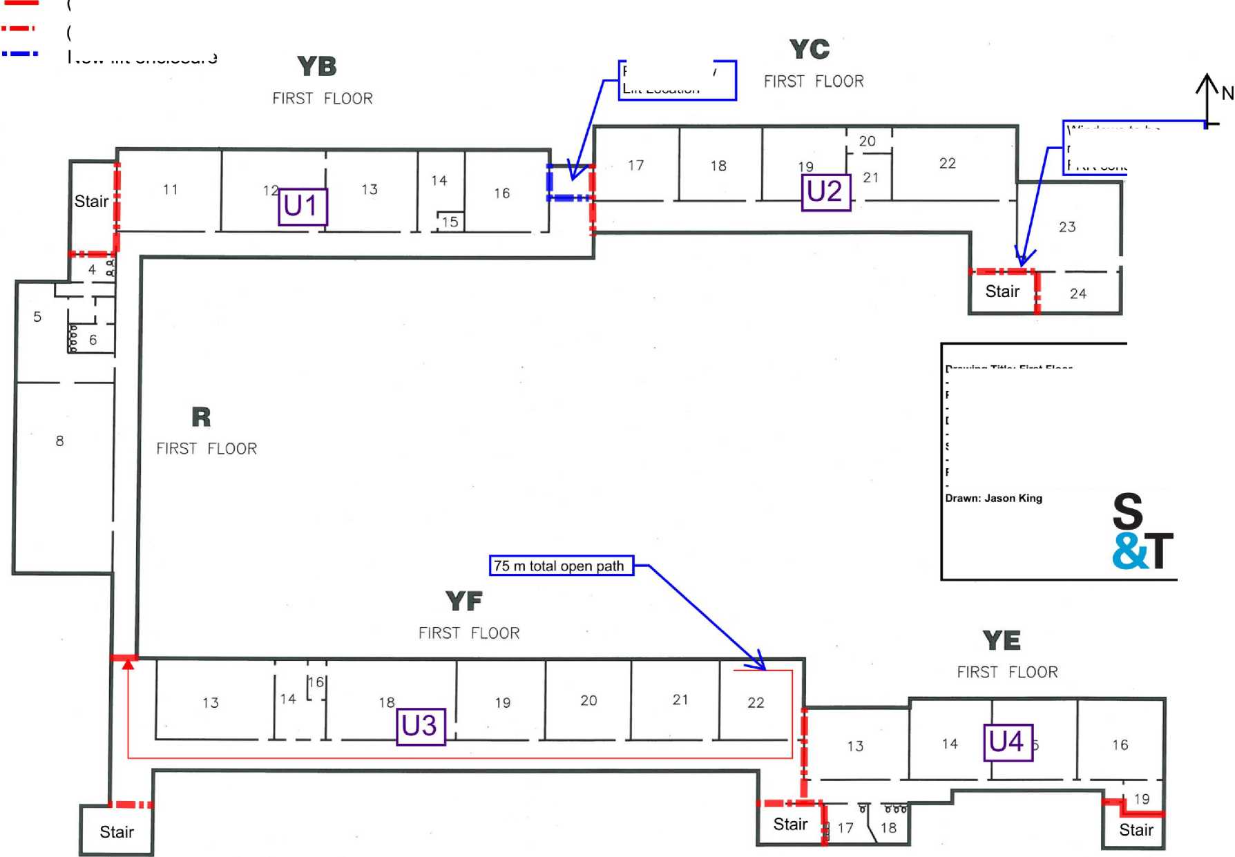 |
Project: Naenae College Scale: NTS Drawing No. FSK02 Rev: 1 Issued: Building Consent Date: 20/07/2016 Project No.: 21422 |
(30)/30/30 FRR walls with -/30/30Sm doors New lift enclosure
Windows to be replaced with -/60/60 FRR construction
□rawing Title: First Floor
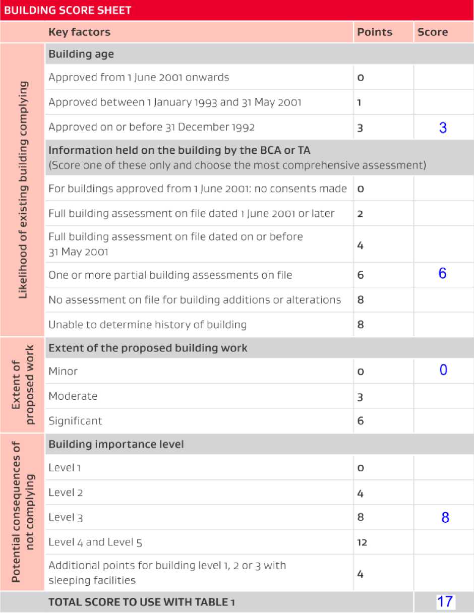

Major Consulting Group Ltd PO Box 25334
Wellington 6146
majorconsulting.co.nz
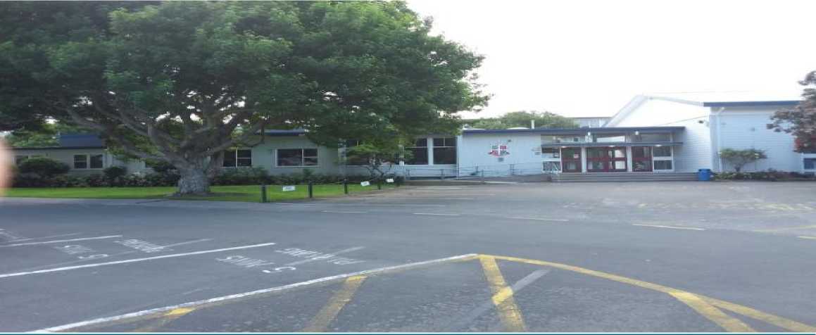
W-01422
Asbestos Refurbishment
Survey Report
Naenae College, 910 High Street, Avalon, Lower Hutt 5011
For:
Frank Bourke
IR Group Ltd
Level 2 / 3 Swan Lane
Te Aro
Wellington 6011
Client W-01422 Date of Report
IR Group Ltd Asbestos Refurbishment Survey 23/12/2021
MCG quality control
|
Project no.: |
W-01422 |
|
Title: |
Asbestos Refurbishment Survey |
|
Client: |
IR Group Ltd Level 2 / 3 Swan Lane Te Aro Wellington 6011 |
|
Client contact: |
Frank Bourke |
|
Date of survey |
20/12/2021 |
|
Date of report: |
23/12/2021 |
|
Office: |
Wellington |
|
Status: |
Final |
|
Surveyor: |
Mike Dunnett |
Signature: |
,4W |
|
Date: |
23/12/2021 |
|
Technical reviewer: |
Becky Lloyd |
Approved reviewer: |
Shelley Major |
|
Signature: |
Signature: | ||
|
Date: |
24/12/2021 |
Date: |
24/12/2021 |
Disclaimer
Major Consulting Group Ltd. (MCG) has prepared this report for the sole use of the client, showing reasonable skill and care, for the intended purposes as stated in the agreement under which this work was completed. The report may not be relied upon by any other party without the express agreement of the client and MCG. No other warranty, expressed or implied, is made as to the professional advice included in this report.
Where any data supplied by the client or from other sources have been used, it has been assumed that the information is correct. No responsibility can be accepted by MCG for inaccuracies in the data supplied by any other party. The conclusions and recommendations in this report assume that all relevant information has been supplied by those bodies from whom it was requested.
Table of Contents

W-01422
Issue Date: 23/12/2021
Frank Bourke from IR Group Ltd engaged Major Consulting Group Limited (MCG) to carry out a targeted asbestos refurbishment survey at Naenae College, 910 High Street, Avalon, Lower Hutt 5011. The purpose of the survey was to identify, as far as reasonably practicable, asbestos-containing material (ACM) that must be removed prior to refurbishment works being undertaken.
The survey was carried out by Mike Dunnett, Asbestos Assessor on 20/12/2021.
Where ACM is found, an asbestos register is developed that details the material to be removed by an appropriately licensed removalist prior to intrusive work commencing. (See Section 3).
Any ACM identified during the refurbishment survey has been assessed using a material risk assessment (see Appendix 5) and categorised according to its potential to release fibres: i.e. high, medium, low and very low risk.
Note, if IR Group Ltd intends to commence works later than three months from the date of the survey, IR Group Ltd will need to actively manage the risk of exposure to respirable fibres. As appropriate, please consult MCG on developing an asbestos management plan.
This report is designed to be kept as a record of assessment of the extent and characteristics of the asbestos found and is based on information made available during the survey on 20/12/2021. This report is not intended as a specification for any removal works. Please talk to us about providing a detailed specification for works if required.
Reports on previous asbestos inspections were not available prior to commencing the survey.
-
1.1 Summary of findings
The table below details the locations that were found to contain asbestos or presumed to contain asbestos, the material risk assessment, and the recommended action for remediation.
Naenae College

|
Floor |
Area / Room |
Material Description |
Sample No. |
Material Risk |
Recommended Action |
|
External |
029 / Eaves |
lower soffit - Cement products |
S011 |
Low (6) |
Remove |
|
External |
002 / External pillar |
cement cladding -Cement products |
S002 |
Low (6) |
Remove |
|
External |
032 / Eaves |
soffit - Cement products |
X011 |
Low (6) |
Remove |
|
External |
003 / North eaves |
soffit - Cement products |
S003 |
Low (5) |
Remove |
|
External |
028 / Eaves |
soffit - Cement products |
X001 |
Low (5) |
Remove |
|
External |
030 / External Walls |
cladding - Cement products |
S012 |
Low (5) |
Remove |
|
External |
001 / Eaves |
soffit - Cement products |
S001 |
Very Low (4) |
Remove |
|
External |
005 / Northwest Corner Cladding |
profiled cement cladding - Cement products |
S005 |
Very Low (4) |
Remove |
W-01422
Issue Date: 23/12/2021
|
Naenae College |
_ |
E E | |||||
|
Floor |
Area / Room |
Material Description |
Sample No. |
Material Risk |
Recommended Action | ||
|
External |
006 / Northwest corner eaves |
soffit - Cement products |
S006 |
Very Low (4) |
Remove |
M CD > U CD X UJ | |
|
External |
006 / Northwest corner pillar |
cement cladding -Cement products |
S007 |
Very Low (4) |
Remove | ||
|
External |
031 / Upper Cladding |
cladding - Cement products |
S014 |
Very Low (4) |
Remove | ||
|
External |
037 / Under iron roof |
Bitumen - Bitumen products |
PS001 |
Very Low (3) |
Remove | ||
The following lists MCG’s key recommendations regarding Naenae College:
+ Check the roof void for asbestos contamination when the roof has been removed to enable an investigation.
+ Any products likely to be disturbed during the refurbishment works should be removed by a class B licensed removalist prior to the works starting.
+ We recommend ensuring all workers are trained to recognise and manage asbestos risks according to the Approved Code of Practice for the Management and Removal of Asbestos (ACOP).
+ If the scope of refurbishment changes or suspect items or dust is identified, immediately contact MCG to conduct further testing.

W-01422
Issue Date: 23/12/2021
The purpose of the refurbishment survey is to identify asbestos-containing materials that could be disturbed during the planned refurbishment work to be removed prior to intrusive or destructive works commencing.
+ The survey was carried out in accordance with Major Consulting Group Ltd’s quality management system.
+ Field investigations have been restricted to a level of detail required to achieve the stated objectives of the work.
+ The survey may have involved destructive surveying methods to gain access to all areas within the agreed scope.
The methodology used for the survey is detailed in Appendix 4.
-
2.1 Site details
Site address: Naenae College, 910 High Street, Avalon, Lower Hutt
5011
Site description: School
Scope of works for the refurbishment survey: Refurbishment survey of administration block
Areas excluded:
No areas were excluded during the survey
As appropriate, the scope included:
-
► A desktop review and discussions with site personnel to determine the history, previous use, existing asbestos register and previous removals of ACM
-
► A site-specific risk assessment prior to starting the survey
-
► A thorough inspection of the site
-
► Documenting potential ACM, their location, type, quantity, condition and stability
-
► Samples taken and submitted to an IANZ-accredited laboratory to detect the absence or
presence of asbestos fibres
-
► Marking up drawings to show the sampling locations
-
► A documented assessment of the materials’ potential to release fibres and recommendations to minimise or manage the risk
-
► Photographs taken to aid the item identification and condition
-
► Signage/labelling requirements.
Unless otherwise agreed, the following areas were out of scope due to the unacceptable risks they present to our surveyors:
-
► The interior of electrical equipment and services
-
► Lift shafts and lift machinery
-
► Areas where destructive investigation would cause unacceptable structural damage or would compromise the safety or security of the premises

W-01422
Issue Date: 23/12/2021
-
► Beneath concrete floor slabs.
15 samples were taken during the course of this survey, and then analysed by a laboratory holding accreditation from International Accreditation New Zealand (IANZ).
C
O
U
73 O
■i—
C
It should be noted that it is possible that some asbestos may remain hidden within the building structure, so care should always be taken during refurbishment work. If suspect material is found, work must cease pending further sampling and analysis.
This report is subject to the service constraints given in Appendix 6.

W-01422
Issue Date: 23/12/2021
The asbestos register records where asbestos-containing material was found during this survey.
A material risk score is also provided.
|
Naenae College Location |
Item |
Material |
Sample no. |
Condition |
Ease of access |
Surface treatment |
Extent |
^M | |||
|
to | |||||||||||
|
External 029 / Eaves |
lower soffit |
Cement products |
S011 |
Low damage: a few scratches or surface marks, broken edges on boards, tiles etc. |
Occasionally disturbed |
Enclosed sprays and lagging, AIB (with exposed face painted or encapsulated) asbestos cement sheets etc. |
12m² |
• _ | |||
|
Asbestos type |
Labelled? |
Material risk score (fibre release potential) |
Recommended action | ||||||||
|
Chrysotile, Amosite, Crocidolite |
No |
Low (6) |
Remove. Engage a Class B licensed asbestos removal contractor to remove this item and any associated ACD. A clearance certificate must be obtained from a licensed asbestos assessor independent of the removalist prior to reoccupation. | ||||||||
£ V) □) O
tn O
O
cn
Asbestos Refurbishment Survey :
Naenae College
W-01422
Issue Date: 23/12/2021

|
Naenae College | ||||||||||||||||||||||||||||||||||
| ||||||||||||||||||||||||||||||||||
£ cn
□) O
tn O
O
tn
|
Naenae College |
|
Location |
Item |
Material |
Sample no. |
Condition |
Ease of access |
Surface treatment |
Extent |
^^^^^^^^^^^^^^1 |
|
External 028 / Eaves |
soffit |
Cement products |
X001 |
Low damage: a few scratches or surface marks, broken edges on boards, tiles etc. |
Usually inaccessible |
Enclosed sprays and lagging, AIB (with exposed face painted or encapsulated) asbestos cement sheets etc. |
30m² | |
|
Asbestos type |
Labelled? |
Material risk score (fibre release potential) |
Recommended action |
^^^^jF | ||||
|
Amosite, Chrysotile |
No |
Low (5) |
Remove. Engage a Class B licensed asbestos removal contractor to remove this item and any associated ACD. A clearance certificate must be obtained from a licensed asbestos assessor independent of the removalist prior to reoccupation. | |||||
Asbestos Refurbishment Survey :
Naenae College

W-01422
Issue Date: 23/12/2021
|
Naenae College | |||||||||||||||||||||||||||||||||||||||||||||||||||||||
| |||||||||||||||||||||||||||||||||||||||||||||||||||||||
|
Naenae College | ||||||||
|
Location |
Item |
Material |
Sample no. |
Condition |
Ease of access |
Surface treatment |
Extent |
/ .Location 1 J Location 2 f |
|
External 037 / Under iron roof |
Bitumen |
Bitumen products |
PS001 |
Low damage: a few scratches or surface marks, broken edges on boards, tiles etc. |
Usually inaccessible |
Composite materials containing asbestos: reinforced plastics, resins, vinyl tiles. |
Throughout | |
|
Asbestos type |
Labelled? |
Material risk score (fibre release potential) |
Recommended action |
p^^r^^^^^ET^8^ ’ " ’ fc*!& Aj. ^1 £ | ||||
|
Chrysotile |
No |
Very Low (3) |
Remove. Engage a Class B licensed asbestos removal contractor to remove this item and any associated ACD. A clearance certificate must be obtained from a licensed asbestos assessor independent of the removalist prior to reoccupation. | |||||
£ cn
□) O
tn O
O
tn
Asbestos Refurbishment Survey :
Naenae College

W-01422
Issue Date: 23/12/2021
|
Naenae College | |||||||||||||||||||||||||||||||||||
| |||||||||||||||||||||||||||||||||||
|
Naenae College | ||||||||||||||||||||||||||||||||||
| ||||||||||||||||||||||||||||||||||
£ cn
□) O
tn O
O
tn
Asbestos Refurbishment Survey :
Naenae College

W-01422
Issue Date: 23/12/2021
|
Naenae College | ||||||||||||||||||||||||||||||||||
| ||||||||||||||||||||||||||||||||||
£ cn
□) O
tn O
O
tn
|
Naenae College | ||||||||||||||||||||||||||||||||
| ||||||||||||||||||||||||||||||||
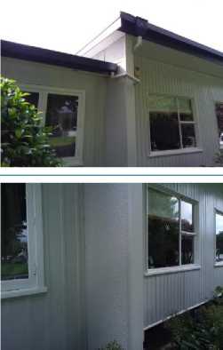
Asbestos Refurbishment Survey :
Naenae College
W-01422
Issue Date: 23/12/2021

|
Naenae College | ||||||||||||||||||||||||||||||||||
| ||||||||||||||||||||||||||||||||||
£ cn
□) O
tn O
O
tn
|
Naenae College | |||||||||||||||||||||||||||||||||||||||||
| |||||||||||||||||||||||||||||||||||||||||
Asbestos Refurbishment Survey :
Naenae College

W-01422
Issue Date: 23/12/2021
|
Naenae College | ||||||||||
|
Location |
Item |
Material |
Sample no. |
Condition |
Ease of access |
Surface treatment |
Extent |
r i e | ||
|
External 031 / Upper Cladding |
cladding |
Cement products |
S014 |
Good condition: no visible damage |
Usually inaccessible |
Enclosed sprays and lagging, AIB (with exposed face painted or encapsulated) asbestos cement sheets etc. |
20m² | |||
|
Asbestos type |
Labelled? |
Material risk score (fibre release potential) |
Recommended action | |||||||
|
Amosite, Chrysotile |
No |
Very Low (4) |
Remove. Engage a Class B licensed asbestos removal contractor to remove this item and any associated ACD. A clearance certificate must be obtained from a licensed asbestos assessor independent of the removalist prior to reoccupation. | |||||||
£ cn
□) O
tn O
O
tn
Asbestos Refurbishment Survey :
Naenae College
W-01422
Issue Date: 23/12/2021

The register below records samples that were taken during this survey that, when analysed, did not show evidence of containing asbestos.
This register must be read in conjunction with the full report. It should not be extracted or used in isolation.
Naenae College

W-01422
Issue Date: 23/12/2021
|
Floor |
Area / Room |
Material |
Approx. m² |
Sample Number |
Result |
|
External |
004 / Windows |
window putty - Mastics and putty |
all items |
S004 |
No asbestos detected in sample. No further action required. |
|
Ground Floor |
020 / Northwest entrance |
cladding - Cement products |
3m² |
S008 |
No asbestos detected in sample. No further action required. |
|
Ground Floor |
023 / Nurses Room |
Vinyl flooring - Vinyl sheeting |
12m² |
S009 |
No asbestos detected in sample. No further action required. |
|
Ground Floor |
024 / Nurse |
Vinyl flooring - Vinyl sheet paperbacked |
15m² |
S010 |
No asbestos detected in sample. No further action required. |
|
Ground Floor |
025 / Sickbay |
Vinyl flooring - Vinyl sheeting |
12m² |
X010 |
No asbestos detected in sample. No further action required. |
|
Ground Floor |
010 / Main entrance |
vinyl flooring - Vinyl sheeting |
42m² |
S015 |
No asbestos detected in sample. No further action required. |
|
Ground Floor |
027 / Kitchen |
paper backing - Paper and felt |
3m² |
S016 |
No asbestos detected in sample. No further action required. |
Asbestos Refurbishment Survey:
Naenae College
No asbestos was found within the walls and roof void. However, a previous sample of the bitumen under the roof has returned a positive result for asbestos. Depending on the condition of the bitumen it is possible that some areas may be contaminated and a full environmental clean of the roof void may have to be undertaken. Because of the construction of the building it is not possible to properly inspect the roof void for possible contamination until the roof is fully removed.
U c
All asbestos material should be removed by a qualified Class B asbestos removalist and a clearance certificate provided by a licensed assessor.
As noted elsewhere, asbestos may remain hidden in the fabric of the building. If any suspicious material is located during the refurbishment, work must immediately stop pending further testing by a competent person.

W-01422
Issue Date: 23/12/2021
Appendix 1: Site plans and sample locations
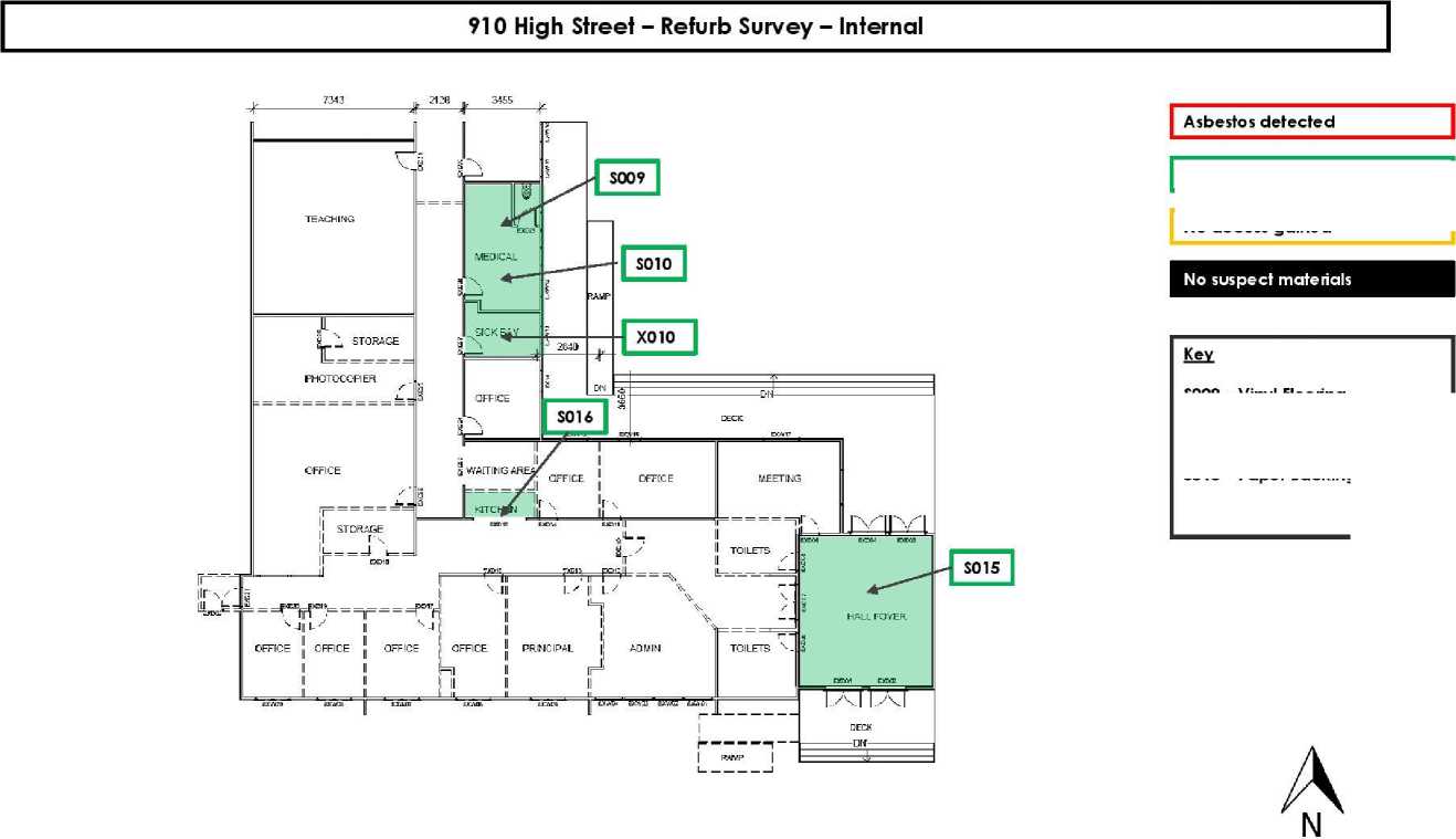 |
No asbestos detected SOO? - Vinyl Flooring S010 - Vinyl Flooring X010 - Vinyl Flooring S015 - Vinyl Flooring S016 - Paper Backing |
CO C O
Q.
0) ^
No access gained
Asbestos Refurbishment Survey :
Naenae College

W-01422
Issue Date: 23/12/2021
910 High Street - Refurb Survey - External
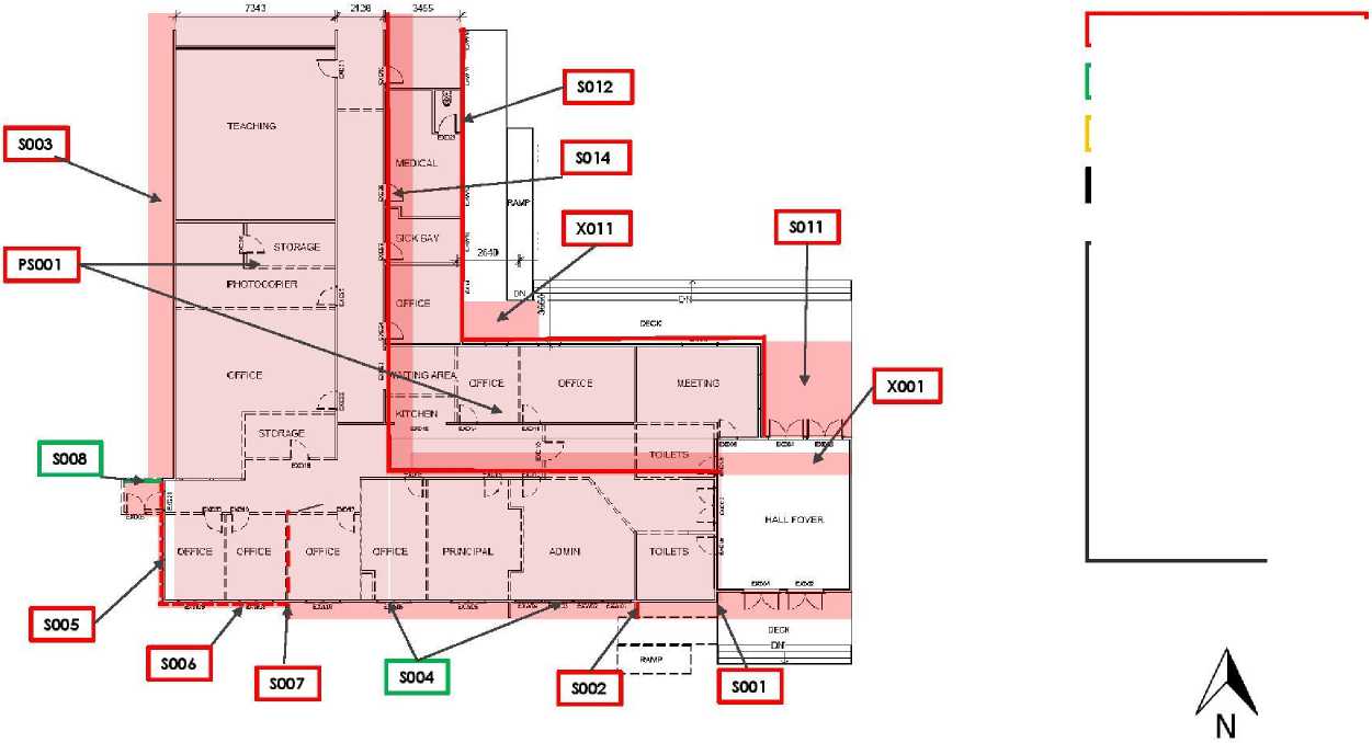
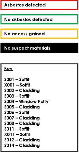
cn C O Q.
0) ■^
Asbestos Refurbishment Survey :
Naenae College
W-01422
Issue Date: 23/12/2021

|
HiU Laboratories Level 3,204 Thorndon Quay Thorndon TRIED, TESTED AND TRUSTED Wellington 60H New Zealand |
T 0508 HILL LAB (44 555 22) T +64 7 858 2000 | |||||||
|
Certificate of Analysis |
Page 1 of 2 1 | |||||||
|
Client: Contact: |
Major Consulting Group Limited Lab No: Shelley Major Date Received: C/- Major Consulting Group Limited Date Reported: PO Box 25334 Quote No: Featherston Street Order NoWellington 6146 Client Reference; Add. Client Ref: Submitted By: |
2807701 21-Dec-2021 22-Dec-2021 89027 W-01422 Date sampled: 20/12/21 Mike Dunnett | ||||||
|
Sample Type: Building Material 1 | ||||||||
|
Sample Name |
Lab Number |
Sample Category* |
Sample Weight on receipt (g) |
Asbestos Presence / Absence |
Description of Asbestos in Non Homogeneous Samples | |||
|
S001 |
2807701.1 |
Fibre Cement |
1.27 |
Amosite (Brown Asbestos) detected. Chrysotile (White Asbestos) detected |
N/A | |||
|
S002 |
2807701.2 |
Fibre Cement |
3.11 |
Amosite (Brown Asbestos) detected. Chrysotile (White Asbestos) detected Crocidolite (Blue Asbestos) detected. |
N/A | |||
|
S003 |
2807701.3 |
Fibre Cement |
1.16 |
Amosite (Brown Asbestos) detected. Chrysotile (White Asbestos) detected. |
N/A | |||
|
S004 |
2807701.4 |
Others |
0.87 |
Asbestos NOT detected. |
N/A | |||
|
S005 |
2807701.5 |
Fibre Cement |
1.04 |
Amosite (Brown Asbestos) detected. Chrysotile (White Asbestos) detected. |
N/A | |||
|
S006 |
2807701.6 |
Fibre Cement |
0.95 |
Chrysotile (White Asbestos) detected. Organic fibres detected. |
N/A | |||
|
S007 |
2807701.7 |
Fibre Cement |
1.60 |
Chrysotile (White Asbestos) detected. |
N/A | |||
|
SOOS |
2807701.8 |
Other #2 |
1.23 |
Asbestos NOT detected. |
N/A | |||
|
8009 |
2807701.9 |
Linoleum /Vinyl floor tile |
2.13 |
Asbestos NOT detected. Organic fibres detected. |
N/A | |||
|
S010 |
2807701.10 |
Linoleum / Vinyl floor tile |
7.64 |
Asbestos NOT detected. Organic fibres detected. |
N/A | |||
|
S012 |
2807701.11 |
Fibre Cement |
1.02 |
Asbestos NOT detected. Organic fibres detected. |
N/A | |||
|
8014 |
2807701.12 |
Fibre Cement |
1.10 |
Amosite (Brown Asbestos) detected. Chrysotile (White Asbestos) detected. |
N/A | |||
|
8015 |
2807701.13 |
Linoleum / Vinyl floor tile |
3.04 |
Asbestos NOT detected. Organic fibres detected. |
N/A | |||
|
8016 |
2807701.14 |
Fibre Cement |
2.45 |
Asbestos NOT detected. Organic fibres detected. |
N/A | |||
|
S011 |
2807701.15 |
Fibre Cement |
1.12 |
Amosite (Brown Asbestos) detected. Chrysotile (White Asbestos) detected. Crocidolite (Blue Asbestos) detected. |
N/A | |||
£ □
u
0)
Glossary of Ter ms
-
• Loose fibres (Minor) - One or twofibres/fibre bundles identified during analysis by stereo microscope/PLM.
-
• Loose fibres (Major) - Three or more fibres/fibre bundles identified during analysis by stereo microscope/PLM.
-
• ACM Debris (Minor) - One or two small (<2mm) pieces of material attached to fibres identified during analysis by stereo microscope/PLM.
-
• ACM Debris (Major) - Large (>2mm) piece, or more than three small (<2mm) pieces of material attached to fibres identified during analysis by stereo microscope/PLM.
-
• Unknown Mineral Fibres - Mineral fibres of unknown type detected by polarised light microscopy including dispersion staining. The fibres detected may or may not be asbestos fibres. To confirm the identities, another independent analytical technique may be required.
-
• Trace - Trace levels of asbestos, as defined by AS4 964-2004.
For further details, please contact the Asbestos Team.
Analyst's Comments
" Putty
m Concrete/Render

This Laboratory is accredited by International Accreditation New Zealand (IANZ), which represents New Zealand in the International Laboratory Accreditation Cooperation (ILAC). Through the ILAC Mutual Recognition Arrangement (ILAC-MRA) this accreditation is internationally recognised.
The tests reported herein have been performed in accordance with the terms of accreditation, with the exception of tests marked * or any comments and interpretations, which are not accredited.
W-01422
Issue Date: 23/12/2021

Summary of Methods
The following tablets) gives a brief description of the methods used to conduct the analyses for this job. The detection limits given below are those attainable in a relatively simple matrix. Detection limits may be higher for individual samples should insufficient sample be available, or if the matrix requires that dilutions be performed during analysis. A detection limit range indicates the lowest and highest detection limits in the associated suiteof analytes. A foil listing of compounds and detection limits are available tom the laboratory upon request. Unless otherwise indicated, analyses were performed at Hill Laboratories, 28 Duke Street, Frankton, Hamilton 3204.
co £ □ U
|
Sample Type: Balding Material | ||||||||||||||||||||||||
| ||||||||||||||||||||||||
|
These samples were collected by yourselves (or your agent) and analysed as received at the laboratory. | ||||||||||||||||||||||||
0)
Testing was completed between 21-Dec-2021 and 22-Dec-2021. For completion dates of individual analyses please contact the laboratory.
Samples are held at the laboratory after reporting for a length of time based onthestability of the samples and analytes being tested (considering any preservation used), and the storage space available. Once the storage period is completed, the samples are discarded unless otherwise agreed with the customer. Extended storage times may incur additional charges.
This certificate of analysis must not be reproduced, except in full, without the written consent of the signatory.
Ashleigh Teal
Section Manager - Asbestos
Lab No: 2807701-A2Pv1 Hill Laboratories Page 2 of 2

W-01422
Issue Date: 23/12/2021
The survey register records all areas that have been surveyed, together with the results of the survey.
£
□)
(I)
Asbestos Refurbishment Survey :
Naenae College
W-01422
Issue Date: 23/12/2021

(I) £
VO
|
Naenae College | ||||||||
|
Floor |
Area / Room |
Location Accessed |
Reason for No Access / Inaccessible Areas / General Room Comment |
Approach |
Photo | |||
|
Ground Floor |
007 / Ladies Bathroom |
Yes |
No suspect materials were identified within the room during the survey |
No Suspect Material | ||||
|
VISITORS ONLY mO STU^5 |
' 1 | |||||||
|
U^K ' | ||||||||
|
Ground Floor |
008 / Mens Bathroom |
Yes |
No suspect materials were identified within the room during the survey |
No Suspect Material | ||||
|
IE33 VISITORS ONLY | ||||||||
|
Ground Floor |
009 / Meeting Room |
Yes |
No suspect materials were identified within the room during the survey |
No Suspect Material | ||||
|
Ground Floor |
011 / Administration Room |
Yes |
No suspect materials were identified within the room during the survey |
No Suspect Material | ||||
£
□)
(I)

Asbestos Refurbishment Survey :
Naenae College
W-01422
Issue Date: 23/12/2021

|
Naenae College | |||||
|
Floor |
Area / Room |
Location Accessed |
Reason for No Access / Inaccessible Areas / General Room Comment |
Approach |
Photo |
|
Ground Floor |
012 / Reception |
Yes |
No suspect materials were identified within the room during the survey |
No Suspect Material | |
|
Ground Floor |
013 / Principals Office |
Yes |
No suspect materials were identified within the room during the survey |
No Suspect Material |
■B1 |
|
Ground Floor |
014 / Resource Managers Room |
Yes |
No suspect materials were identified within the room during the survey |
No Suspect Material |
NIB |
|
Ground Floor |
015 / Principal Assistant |
Yes |
No suspect materials were identified within the room during the survey |
No Suspect Material |
1 ^i^^^BH si |
£
□)
(I)

Asbestos Refurbishment Survey :
Naenae College
W-01422
Issue Date: 23/12/2021

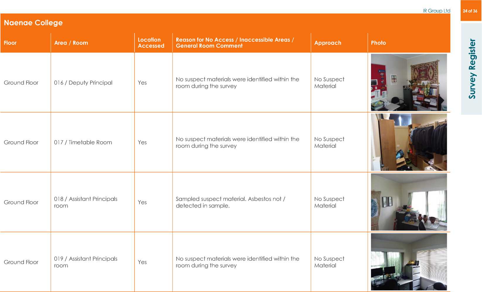
Asbestos Refurbishment Survey :
Naenae College
W-01422
Issue Date: 23/12/2021

Naenae College
|
Floor |
Area / Room |
Location Accessed |
Reason for No Access / Inaccessible Areas / General Room Comment |
Approach |
Photo |
|
Ground Floor |
021 / Administration Specialist room |
Yes |
No suspect materials were identified within the room during the survey |
No Suspect Material |
1 ■*1 ■? |
|
Ground Floor |
022 / Photo copy room |
Yes |
No suspect materials were identified within the room during the survey |
No Suspect Material |
aS *' |
|
Ground Floor |
026 / Storage |
Yes |
No suspect materials were identified within the room during the survey |
No Suspect Material | |
|
Ground Floor |
020 / north west entrance |
Yes |
Sampled suspect material. Asbestos not detected in sample. |
Sampled S008 |
Ml 1_____i |
£
□)
(I)

Asbestos Refurbishment Survey :
Naenae College
W-01422
Issue Date: 23/12/2021

|
Naenae College | ||||||||
|
Floor |
Area / Room |
Location Accessed |
Reason for No Access / Inaccessible Areas / General Room Comment |
Approach |
Photo | |||
|
Ground Floor |
023 / Nurses Room |
Yes |
Sampled suspect material. Asbestos not detected in sample. |
Sampled S009 | ||||
|
Ground Floor |
024 / Nurse |
Yes |
Sampled suspect material. Asbestos not detected in sample. |
Sampled S010 | ||||
|
Ground Floor |
010 / Main entrance |
Yes |
Sampled suspect material. Asbestos not detected in sample. |
Sampled S015 |
JI | |||
|
Ground Floor |
027 / Kitchen |
Yes |
Sampled suspect material. Asbestos not detected in sample. |
Sampled S016 |
tn |
^ I | ||
£
□)
(I)

Asbestos Refurbishment Survey :
Naenae College
W-01422
Issue Date: 23/12/2021

Naenae College
|
Floor |
Area / Room |
Location Accessed |
Reason for No Access / Inaccessible Areas / General Room Comment |
Approach |
Photo |
|
Ground Floor |
025 / Sickbay |
Yes |
Sampled suspect material. Asbestos not detected in sample. |
Cross Reference X010 | |
|
External |
029 / Eaves |
Yes |
Sampled suspect material. Asbestos detected in sample. |
Sampled S011 |
£
□)
(I)

Asbestos Refurbishment Survey :
Naenae College
W-01422
Issue Date: 23/12/2021

|
Naenae College | |||||
|
Floor |
Area / Room |
Location Accessed |
Reason for No Access / Inaccessible Areas / General Room Comment |
Approach |
Photo |
|
External |
033 / Eaves |
Yes |
No suspect materials were identified within the room during the survey |
No Suspect Material | |
|
External |
037 / Under iron roof |
Yes |
Sampled suspect material. Asbestos detected in sample. |
Previously Sampled PS001 |
%**^v/^ A|^| £ ^ ^ . 77 |
|
External |
001 / Eaves |
Yes |
Sampled suspect material. Asbestos detected in sample. |
Sampled S001 | |
|
External |
002 / External pillar |
Yes |
Sampled suspect material. Asbestos detected in sample. |
Sampled S002 | |
£
□)
(I)
(I) £
VO
Asbestos Refurbishment Survey :
Naenae College
W-01422
Issue Date: 23/12/2021

|
Naenae College | |||||
|
Floor |
Area / Room |
Location Accessed |
Reason for No Access / Inaccessible Areas / General Room Comment |
Approach |
Photo |
|
External |
003 / North eaves |
Yes |
Sampled suspect material. Asbestos detected in sample. |
Sampled S003 |
^^1 |
|
External |
004 / Windows |
Yes |
Sampled suspect material. Asbestos not detected in sample. |
Sampled S004 | |
|
External |
005 / Northwest Corner Cladding |
Yes |
Sampled suspect material. Asbestos detected in sample. |
Sampled S005 |
al |
|
External |
006 / Northwest corner eaves |
Yes |
Sampled suspect material. Asbestos detected in sample. |
Sampled S006 |
Ai |
£
□)
(I)
(I) £
VO
Asbestos Refurbishment Survey :
Naenae College
W-01422
Issue Date: 23/12/2021

|
Naenae Coll Floor |
ge Area / Room |
Location Accessed |
Reason for No Access / Inaccessible Areas / General Room Comment |
Approach |
Photo | ||
|
External |
006 / Northwest corner pillar |
Yes |
Sampled suspect material. Asbestos detected in sample. |
Sampled S007 | |||
|
External |
030 / External Walls |
Yes |
Sampled suspect material. Asbestos detected in sample. |
Sampled S012 | |||
|
External |
031 / Upper Cladding |
Yes |
Sampled suspect material. Asbestos detected in sample. |
Sampled S014 | |||
|
-^witurrr |
8 | ||||||
|
External |
028 / Eaves |
Yes |
Sampled suspect material. Asbestos detected in sample. |
Cross Reference X001 |
1 ‘ M | ||
£
□)
(I)

Asbestos Refurbishment Survey :
Naenae College
W-01422
Issue Date: 23/12/2021

|
Naenae College | |||||
|
Floor |
Area / Room |
Location Accessed |
Reason for No Access / Inaccessible Areas / General Room Comment |
Approach |
Photo |
|
External |
032 / Eaves |
Yes |
Sampled suspect material. Asbestos detected in sample. |
Cross Reference X011 |
7 1' |
£
□)
(I)
(I) £
VO
Asbestos Refurbishment Survey :
Naenae College
W-01422
Issue Date: 23/12/2021

Appendix 4: Survey methodology and limitations
MCG’s survey methodology is based on:
+ The New Zealand Approved Code of Practice for the Management and Removal of Asbestos
+ WorkSafe NZ’s guidance for conducting asbestos surveys
+ The UK Health and Safety Executive’s guidance document Asbestos: The Survey Guide (HSG 264) + ISO17020:2013 detailing the internationally accepted standards for performing inspections
Sampling was carried out in a manner designed to create minimal disturbance in accordance with published guidance and documented methods; however, it may have involved destructive techniques to get into the fabric of the structure. Hand tools and dust suppression techniques were employed to limit the potential generation of respirable fibres.
All samples collected were appropriately labelled and securely double-bagged whilst on site, prior to analysis by an accredited laboratory. Sampling points were sealed as appropriate to prevent fibre release.
Once all works associated with the asbestos refurbishment survey were completed, a visual assessment of the areas surveyed was carried out and, where necessary, made good to ensure that the site was suitable for reoccupation.
It was not felt necessary to appoint a licensed asbestos removal contractor to facilitate access to all areas on site.
-
4.3 Limitation of an asbestos refurbishment survey During the course of the survey, all efforts were made to identify the presence of materials containing asbestos within areas of the building as agreed with you.
It must be noted that asbestos materials are frequently concealed within the fabric of buildings or within sealed building voids; accordingly, it is not possible to regard the findings of any survey as being definitive. It must always remain a possibility therefore that further asbestos-containing material may be found during other activities.
MCG cannot accept any liability for the report not containing information on concealed spaces which may exist within the fabric of the building where the extent and presence of these is not evident at the time of the survey. We accept no liability where additional ACM is found during refurbishment activities. Accordingly, the Client is advised to make provision during the course of any refurbishment for the additional services of a suitably experienced surveyor/specialist to provide advice and/or take samples and/or provide supplementary report(s) in the event that additional ACM is uncovered during the course of the refurbishment.
All areas which have not been accessed must be presumed to contain asbestos until investigation and sampling proves otherwise.
Guidance on work with asbestos can be found in the Health and Safety at Work (Asbestos) Regulations 2016 and Approved Code of Practice for the Management and Removal of Asbestos. Additional relevant information is also available in various HSE guidance notes including HSG213, HSG247, HSG189/2 and HSG227.

W-01422
Issue Date: 23/12/2021
 |
|
0) co tn CD V» v> |
Materials that are identified positive for asbestos during the survey are allocated a material assessment score to indicate the type and condition of the ACM, and its potential to release fibres. The material risk assessment guides the recommendations to minimise the risk of exposure to respirable asbestos fibres.
□
The table below shows the algorithm used for calculating the risk.
|
Sample Variable |
Score |
Examples |
|
Product type (or debris from product) |
1 (Low) |
Composites (plastics, resins, mastics, roofing felts, vinyl floor tiles, paints, decorative finishes, cement etc.) |
|
2 (Medium) |
AIB, textiles, gaskets, ropes, paper etc. | |
|
3 (High) |
Lagging, spray coatings, loose asbestos etc. | |
|
Extent of damage |
0 (None) |
No visible damage. |
|
1 (Low) |
Few scratches/marks, broken edges etc. | |
|
2 (Medium) |
Significant breakage of non-friable materials or several areas of damage to friable material. | |
|
3 (High) |
High damage/visible debris. | |
|
Surface Treatment |
0 (None) |
Non-friable composite asbestos/encapsulated cement. |
|
1 (Low) |
Enclosed sprays/lagging/board or bare cement. | |
|
2 (Medium) |
Bare AIB or encapsulated lagging/spray. | |
|
3 (High) |
Unsealed lagging/spray/loose asbestos. | |
|
Asbestos Type |
1 |
Chrysotile. |
|
2 |
Amphibole asbestos excluding Crocidolite. | |
|
3 |
Crocidolite. |
The material risk assessment score is calculated by adding the scores above to show the correlation to exposure risk, as shown in the table below.
|
Material Assessment Score |
Fibre Release Potential |
|
10 or higher |
High |
|
7 – 9 |
Medium |
|
5 – 6 |
Low |
|
4 or lower |
Very Low |
Scores of 7 or more indicate that urgent attention is required. Scores of 6 or less may be deemed nonurgent. However, this is only used as a guide: specific recommendations are given with the survey results detailed in the asbestos register.

W-01422
Issue Date: 23/12/2021
Appendix 6: Service constraints
co H— c
□
U
</> c o u
(D U
-
1. This report and the asbestos survey carried out in connection with this report (together the "Services") were compiled and carried out by Major Consulting Group Ltd (MCG) for IR Group Ltd (the Client) in accordance with the terms of a contract between MCG and the Client dated 23/11/2021. The Services were performed by MCG with the skill and care ordinarily exercised by a reasonable Asbestos Consultant at the time the Services were performed. The Services were performed by MCG having regard to the limits of the scope of works required by the client, the time scale involved and the resources, including financial and manpower resources, agreed between MCG and the Client.
co
-
2. Other than that expressly contained in paragraph 1 above, MCG provides no other representation or warranty whether express or implied, in relation to the Services.
-
3. Unless otherwise agreed, the Services were performed by MCG exclusively for the Client. Unless expressly provided in writing, MCG does not authorise, consent or condone any party other than the Client relying upon the Services. Should this report or any part of this report or otherwise details of the Services or any part of the Services be made known to any such party, and such party relies thereon, that party does so wholly at its own and sole risk and MCG disclaims any liability to such parties.
-
4. It is MCG's understanding that this report is to be used for the purpose described in the introduction to the report. That purpose was a significant factor in determining the scope and level of the Services. Should the purpose for which the report is used, or the proposed use of the site change, this report may no longer be valid and any further use of or reliance upon the report in those circumstances by the Client without MCG's review and advice shall be at the Client's sole and own risk. Should MCG be requested to review the report after the date hereof, MCG shall be entitled to additional payment at the then existing rates or such other terms as agreed between MCG and the Client.
-
5. The passage of time may result in changes in site conditions, regulatory or other legal provisions, technology or economic conditions which could render the report inaccurate or unreliable. The information and conclusions contained in this report should not be relied upon in the future without the written advice of MCG. In the absence of such written advice by MCG, reliance on the report in the future shall be at the Client's own and sole risk. Should MCG be requested to review the report in the future, MCG shall be entitled to additional payment at the then existing rate or such other terms as may be agreed between MCG and the Client.
-
6. The observations and conclusions described in this report are based solely upon the Services which were provided pursuant to the agreement between the Client and MCG. MCG has not performed any observations, investigations, studies or testing not specifically set out or required by the contract between the Client and MCG. MCG is not liable for the existence of any condition, the discovery of which would require performance of services not otherwise contained in the Services. For the avoidance of doubt, unless otherwise expressly referred to in the introduction to this report, MCG did not seek to evaluate the presence on or off the site of asbestos, electromagnetic fields, lead paint, heavy metals, radon gas or other radioactive or hazardous materials.

W-01422
Issue Date: 23/12/2021
-
7. The Services are based upon MCG's observations of existing physical conditions at the Site gained from a walk-over survey of the site together with MCG's interpretation of information, including documentation, obtained from third parties and from the Client on the history and usage of the site. The Services are also based on information and/or analysis provided by independent testing and information services or laboratories upon which MCG was reasonably entitled to rely. The Services clearly are limited by the accuracy of the information reviewed by MCG and the observations possible at the time of the walk-over survey. Further MCG was not authorised and did not attempt to independently verify the accuracy or completeness of information, documentation or materials received from the Client or third parties, including laboratory and information services, during the performance of the Services. MCG is not liable for any inaccurate information or conclusions; the discovery of which inaccuracies required the doing of any act including the gathering of any information which was not reasonably available to MCG and including the doing of any independent investigation of the information provided to MCG save as otherwise provided in the terms of the contract between the Client and MCG.
-
8. The site drawings provided in this report are not meant to be an accurate base plan but are used to present the general relative locations of features on and surrounding the site.
v> ■4— c
□
v> C o u
0) u
VO

W-01422
Issue Date: 23/12/2021

|
The following is a list of the different asbestos types: | ||||||||||||||
|
a V» V) O 0
|
The following terms, abbreviations and acronyms may appear in the text of this report: | ||||||||||||||||||||||||
|
W-01422
Issue Date: 23/12/2021

▲▲▲
RESOLVE'?
ARCHITECTS
MINISTRY OF EDUCATION
TE TĀHUHU O TE MĀTAURANGA
Detailed Design Report
Weathertightness Remediation
Administration Building at Naenae College
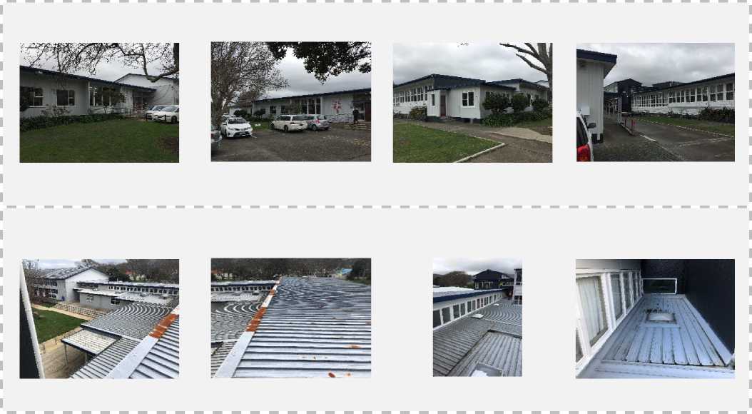 |
|
July 2022 |
Prepared By: Resolve It Architects Ltd
For the Ministry of Education
Version 1.0 Template, September 2019
 |
|
MINISTRY OF EDUCATION TE TĀHUHU O TE MĀTAURANGA |
Document Control Records
Document Prepared by:
Resolve It Architects Ltd
L1 171 Vivian Street
Te Aro
Wellington
Telephone: 04 903 4976
Email: info@resolveitarchitects.co.nz
Revision History
|
Revision No. |
Prepared By |
Description |
Date |
|
01 |
Nigel Ball |
Architect |
220814 |
Document Acceptance
|
Action |
Name |
Position |
Signed |
Date |
|
Prepared by: |
Nigel Ball |
Architect |
220814 | |
|
Reviewed by: |
Mark Ansell |
Director |
220814 | |
|
Approved by: |
Mark Ansell |
Director |
220814 |
Table of Contents
Appendix A - Architectural Documents 16
1 Introduction
-
1.1 Purpose of Report
The purpose of this Detailed Design report is to clearly present to the Ministry of Education the remedial work solutions that will address the identified weathertightness failures that are causing consequential damage to the building. In addition, it records the following –
-
1. Any changes to the solutions, weathertightness failures and/or consequential damage identified in the Preliminary Design report, and the reasons for these changes.
-
2. Descriptions of the means of achieving building code compliance, with more detailed descriptions of the rationale behind any alternative solutions, adequate to support any building consent application;
-
3. A description of any proprietary systems used, with more detailed descriptions of, and rationale for, any variations from manufacturers’ literature, adequate to support any building consent application;
-
4. A description of specific remediation work sections included in the Detailed Design specification;
-
5. A description of the construction phase QA procedures to be included in the Detailed Design documentation;
-
6. A list of the required inspections to be carried out by the designer, if not clearly identified in the QA procedures; and
-
7. A list of any specific remediation works requiring specific skills that may not be within the usual competencies of a remediation contractor.
This report may also be provided to other interested parties including the School’s BoT and Building Consent Authority when a building consent application for the works is being lodged.
-
1.2 Project Overview
The Naenae College administration block is a single level L shaped building, the ends of each wing join against adjacent blocks: a classroom block to the east and the Hall lobby to the south. It has timber framed windows and a variety of cladding types including fibre cement sheet and vertical shiplap timber. The roof consists of two large mono-pitch upper roofs and a lower-level section of roof below the clerestory window line on the inside elevation of the L configuration, all roofs are clad with longrun metal roofing. The roofs on the clerestory side are set at a minimal and/or insufficient falls with little to no upstand against the clerestory windowsills. The block has been added to over the years which has contributed to a complicated the roofscape with poorly flashed junctions and sections of roof with insufficient low pitch, this has resulted in the roof cladding degradation and blockages from leaf litter.
The scope of this developed design is for the exterior envelope, including both the roof cladding and exterior wall claddings, it also includes changes to the exterior envelope due to the interior layout changes. Remediation of the roofs necessitates the replacement of the clerestory windows with new aluminium framed windows resized to allow for compliant sill clearances from the new roof.
-
1.2.1 Weathertightness Scope
The admin building’s weathertightness scope is limited to the roofing works and clerestory windows. The existing roofs are to be remediated by installing a new overlay roof system over the existing longrun metal roofing. The lower section of the roof on the courtyard side is to be re-pitched to provide the required falls and this necessitates the replacement of the clerestory windows to achieve compliant sill clearances from the new roof.
-
1.2.2 Non-Weathertightness Scope
The interior layout has been the subject of a review and redesign by IR Group. This has resulted in changes to the exterior envelope and structure which include:
-
• Engineered beams and posts due to interior layout changes
-
• New public entrance on the west elevation
-
• New student’s entrance on the courtyard side (East)
-
• New wall cladding over a drained and vented cavity to North and West elevations
-
• Four new windows and the new public entrance door to the North and West elevations receiving new wall cladding
-
• Two new windows and the new student entrance door into direct fixed wall cladding on the courtyard side (East) necessitated by interior layout changes.
-
• Relocation of wash/toilets complete with mechanical extraction
-
• New accessible ramp and decking to public side
-
1.3 Project Team
The Project Team members involved are listed as follows:
Role
Name
Company
Ministry’s Project Lead
Kevin Currin
Ministry of Education
Project Manager
Frank Bourke
IR Group
Architect / Designer
Mark Ansell / Nigel Ball
Resolve It Architects Ltd
Timber remediation specialist
Structural Engineer
Hayden Milburn / Joseph Bond
Spencer Holmes Ltd
Mechanical Engineer
Electrical Engineer
Hydraulic Engineer
Fire Engineering
A Fiton
Stephenson & Turner NZ Ltd
Other (list)
2 General Information
-
2.1 Building Location
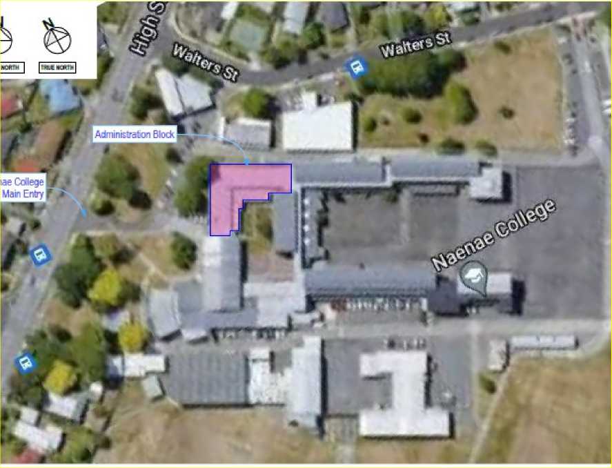
-
2.2 Building Overview
Building
School Block and street address
Naenae College
910 High Street, Avalon, Lower Hutt.
Ministry’s Block Name/ Description and storeys
Admin block: 1 storey building
Function of building
Administration
Known Standard Design
N/A
Year of design (approx.) - is construction 1995 onwards?
1950’s with minor additions
Construction
Foundation/flooring system(s)
Concrete perimeter and concrete piles, timber flooring.
Wall/Cladding/System(s)
Timber weather board fibre cement sheet (Direct fixed)
Roof system(s)
Longrun Metal
Roof slope(s)
Estimate 2-3 degrees for upper roofs and 1-2 degrees for lower roof.
Building
Exterior joinery material
Timber and steel
Other relevant construction details
Timber decking to courtyard side
Site
Wind zone (refer NZS 3604)
Very High
Exposure zone (refer nzs 3604)
Zone C
Snow loading (refer NZS 3604)
N/A
Rainfall (mm/hr) (refer E1/AS1)
70
Climate Zone (refer clause H1)
Zone 2
Earthquake Zone (refer NZS 3604)
Zone 3
-
2.3 Existing reports
The relevant reports that relate to the existing building are listed as follows:
Report Title
Company
Revision and Date
Fire Engineering Report Naenae College Admin
Stephenson Turner
July 2021
Naenae College - MCG - Asbestos Survey
Major Consulting Group
23/12/2021
-
2.4 Weathertightness Issues and Constraints
The Administration Block roofs have exceed their weathertightness lifespan and require immediate remediation or replacement. Asbestos has also been identified in the build up of the existing roof construction so the proposed weathertightness remediation solution is to install an overlay system over the all of the existing roof cladding.
-
3 Weathertightness Failure
-
3.1 Ministry’s Chosen Scope of Work
-
3.1.1 Remediation Inspection Report
-
-
The weathertightness failures and consequential damage identified in the Remediation Inspection report, and that the Ministry has decided to address are summarised as follows:
N/A
-
3.1.2 Additional Failures or Damage
Further to our engagement, the following additional weathertightness failures and consequential damage that have been identified and confirmed by the Ministry to be addressed are summarised as follows:
N/A
-
4 Design Response
-
4.1 Proposed Remedial Work
-
This project involves the installation of a new overlay roof system over the existing longrun trough roof cladding. The over lay roof system make-up consists of PIR boards within the troughs of the existing roof cladding, a vapour control layer, a layer of PIR sheet and weather proofed with waterproof membrane outer layer.
Other work included in the project are a result of the redesign of the interior which include:
-
• Engineered beams and posts due to interior layout changes
-
• New public entrance on the west elevation
-
• New student’s entrance on the courtyard side (East)
-
• New wall cladding over a drained and vented cavity to North and West elevations
-
• Four new windows and the new public entrance door to the North and West elevations receiving new wall cladding
-
• Two new windows and the new student entrance door into direct fixed wall cladding on the courtyard side (East) necessitated by interior layout changes.
-
• Relocation of wash/toilets complete with mechanical extraction
-
• New accessible ramp and decking to public side
-
4.2 Upgrades and Substitutions
The roof remediation and interior layout redesign has resulted in the following upgrades and substitutions:
-
• The existing roofs where required shall be raised to 2 degrees minimum. Roofs will be simplified where practicable, N-S upper-level roof extended to create a singular mono-pitch roof.
-
• New aluminium doubled glazed clerestory windows resized to allow for compliant sill clearances from the new overlay roof system.
-
• Dome polycarbonate skylights to be replaced with new double-glazed skylights
-
• New Engineer specified beams and posts resulting from interior layout redesign.
-
• New exterior cladding will be installed over a drained and vented cavity (North and West elevations).
-
• New aluminium double glazed windows when requiring new replacing existing windows.
-
• New public entrance, accessible ramp, and timber deking to the West elevation
-
• New student entrance to the East elevation
-
4.3 Means of Building Code compliance
The weathertightness remediation design is in accordance with E2/AS1, with all roof falls in compliance with the acceptable solution. A summary of the roofing systems and wall cladding compliance is set out below:
-
• Roof pitches increased to 2 degrees minimum for new membrane clad roofs
-
• New trusses designed by truss manufacture for the extension of the upper-level N-S roof.
-
• Roofs over-clad with overlay roof system, installation to manufacturers details (Waterproof membrane; RoofLogic Fibretite)
-
• New wall cladding: fibre cement panels and vertical shiplap boards over a drained and vented cavity, paint finished.
-
• All external cladding designed to manufactures proprietary systems over a drained and vented cavity.
-
• Upgrade passive fire as per requirements set out in the Fire Engineers Section 112 Assessment.
-
4.4 Construction Phase QA procedures
A project specific QA plan will be prepared using the MOE standard template and utilised during the construction phase.
-
5 Design Checklist
-
5.1 Preliminary Design Stage
-
Architects / Designers are required to answer all questions in this section as part of their Preliminary Design Report. The checkboxes in the list are activated by a double click in MS Word. If any of the ‘No’ or ‘N/A’ boxes are checked, explanatory notes must be provided in the comments’ column.
Compliance
Yes
No
N/A
Comments
|
General |
Yes |
No |
N/A |
Comments |
|
Do the latest plans and amendments show changes (clouded) with version numbering and dates? |
KI | |||
|
Is a project specific QA plan being developed? |
KI | |||
|
Are the outline specification notes project specific? |
K |
Refer Project Specification | ||
|
Have recommendations from the Remediation Inspection Report been incorporated? |
I | |
KI |
No Remediation Inspection Report | |
|
Have any scope changes from the Remediation Inspection Report been recorded and justified? |
I | |
I | |
K | |
|
Has a check been made to establish whether the existing building requires any seismic strengthening? |
I | |
K |
(this issue should be confirmed with the Ministry) | |
|
Has a check been made to establish whether the existing building needs any fire engineering input? |
K |
Refer to Section 112 Assessment | ||
|
Has a check been made to establish whether there are any asbestos containing materials (ACM) in the existing building & if so, has a demolition survey been prepared? |
KI |
□ |
□ |
ACM Report appended |
If an Alternative Solution being proposed, has a supporting rationale been provided?
If proprietary systems are being used, is there a BRANZ Appraisal, codemark or other form of certification?
Have the limitations of a codemark or BRANZ Appraisal been considered and addressed?
Has a check been made to determine whether the building’s occupants need to be vacated during the remediation works?
□ □ K
^ □ □
^ □ □
□
(this issue should be confirmed with the Ministry)
|
Compliance Yes No N/A |
Comments |
|
Surface Water Yes No N/A |
Comments |
|
Are floor and finished ground levels shown on the plan? Are finished ground levels formed to carry water away from the building? Has the size and capacity of channel drains been checked? Has the size and capacity of roof gutters and downpipes been checked? |
Either existing compliant condition or new future landscaping design by others Existing remain unchanged |
|
Structure Yes No N/A |
Comments |
|
Has a check been made to establish whether any existing wall bracing elements 0 □ are affected? |
Designed by Structural Engineer |
|
Timber Framing Yes No N/A |
Comments |
Is a timber remediation expert to be employed during the construction phase?
|
Wall Cladding Yes No N/A |
Comments |
If the cladding system has open (expressed)
joints, has a Rigid Air Barrier (RAB) system □ □
been incorporated?
Do existing cladding systems have sufficient clearance above finished ground levels?
Has an option to increase the durability of
the new cladding system been considered K □ and / or discussed with the Ministry?
|
Roofing |
Yes |
No |
N/A |
Comments |
|
Has a rationale been provided if replacing existing roof surfaces and the existing falls are less than recommended? |
KI | |||
|
Have membrane fall heights been calculated to ensure they can be achieved on site (e.g. clashes with high level window sills)? |
|X| |
□ |
□ |
Roof pitches to be raised to 2 degrees minimum where required |
|
Where a change of roofing is proposed (from membrane to metal roofing), have the acoustic ramifications been considered and allowed for? |
□ |
□ |
K | |
|
Have maintenance requirements of all material and system selections been considered? Provide comment. |
KI |
□ |
□ |
Existing configuration, pitches, condition and budget have led to the proposed overlay roof system being selected as the solution to best satisfying all design considerations. |
-
5.2 Detail Design Stage
Architects / Designers are required to answer all questions in this section as part of their Detail Design Report. The checkboxes in the list are activated by a double click in MS Word. If any of the ‘No’ or ‘N/A’ check boxes are checked, explanatory notes must be provided in the comment’s column.
|
General |
Yes |
No |
N/A |
Comments |
|
Do the latest plans and amendments show changes (clouded) with version numbering and dates? |
KI | |||
|
Has a project specific construction phase QA plan been provided? |
□ |
KI |
□ |
Pending |
|
Is the specification project specific? |
KI |
□ |
□ | |
|
Have large scale details for all key flashings, junctions, changes of plane and assembly details been provided at 1:5 or 1:2 scale? |
KI |
□ |
□ | |
|
Have 3D views of all complex flashing details been provided? |
KI |
□ |
□ | |
|
If required as a part of the project, have seismic strengthening issues been coordinated with the weathertightness remediation works? | ||||
|
If required as a part of the project, have fire engineering issues been coordinated with the weathertightness remediation works? |
K |
□ |
Refer Fire Report | |
|
Has a timber remediation section been included in the specification? |
KI |
□ |
□ | |
|
Has the design considered thermal expansion for metal roofs (particularly roofs with sheet length/ flashings/ gutters over 12m in length)? |
□ |
□ |
KI |
Membrane roof cladding |
|
Has the metal roof design been checked for aggravated thermal bridging? |
K | |||
|
Has a check been done to confirm material compatibility of all external envelope components? |
K |
1 1 |
I | | |
|
Has full design coordination been undertaken with other consultants (structural engineer, mechanical engineer etc.) |
KI |
□ |
□ |
Structural |
Appendix A - Architectural Documents
Drawings
|
Title |
Size |
Drawing number |
Revision |
Date |
|
Location Plan |
A1 |
000 |
A |
14/08/2022 |
|
General Notes |
A1 |
001 |
A |
14/08/2022 |
|
Plan – Ground – Existing/Demo |
A1 |
100 |
A |
14/08/2022 |
|
Plan – Clerestory – Existing/Demo |
A1 |
101 |
A |
14/08/2022 |
|
Plan – Roof – Existing/Demo |
A1 |
102 |
A |
14/08/2022 |
|
Plan – Ground – Proposed |
A1 |
110 |
A |
14/08/2022 |
|
Plan – Clerestory – Proposed |
A1 |
111 |
A |
14/08/2022 |
|
Plan – Roof – Proposed |
A1 |
112 |
A |
14/08/2022 |
|
Plan – Rainfall Calculation |
A1 |
113 |
A |
14/08/2022 |
|
Elevations - Existing |
A1 |
200 |
A |
14/08/2022 |
|
Elevations - Existing |
A1 |
201 |
A |
14/08/2022 |
|
Elevations - Proposed |
A1 |
210 |
A |
14/08/2022 |
|
Elevations - Proposed |
A1 |
211 |
A |
14/08/2022 |
|
3D Views - Proposed |
A1 |
212 |
A |
14/08/2022 |
|
3D Views – Existing & Proposed |
A1 |
213 |
A |
14/08/2022 |
|
3D Views – Existing & Proposed |
A1 |
214 |
A |
14/08/2022 |
|
Sections |
A1 |
300 |
A |
14/08/2022 |
|
Sections |
A1 |
301 |
A |
14/08/2022 |
|
Sections |
A1 |
302 |
A |
14/08/2022 |
|
Sections – Proposed Enlarged 1:20 |
A1 |
303 |
A |
14/08/2022 |
|
Sections – Proposed Enlarged 1:20 |
A1 |
304 |
A |
14/08/2022 |
|
Construction Details |
A1 |
500 |
A |
14/08/2022 |
|
Construction Details |
A1 |
501 |
A |
14/08/2022 |
|
Construction Details |
A1 |
502 |
A |
14/08/2022 |
|
Construction Details |
A1 |
503 |
A |
14/08/2022 |
|
Construction Details |
A1 |
504 |
A |
14/08/2022 |
|
Construction Details |
A1 |
505 |
A |
14/08/2022 |
|
Construction Details |
A1 |
506 |
A |
14/08/2022 |
|
Construction Details |
A1 |
507 |
A |
14/08/2022 |
|
Construction Details |
A1 |
508 |
A |
14/08/2022 |
|
Construction Details |
A1 |
509 |
A |
14/08/2022 |
|
Construction Details |
A1 |
510 |
A |
14/08/2022 |
|
Construction Details |
A1 |
511 |
A |
14/08/2022 |
|
Construction Details |
A1 |
512 |
A |
14/08/2022 |
|
Construction Details |
A1 |
513 |
A |
14/08/2022 |
|
Construction Details |
A1 |
514 |
A |
14/08/2022 |
|
Construction Details |
A1 |
515 |
A |
14/08/2022 |
|
Construction Details |
A1 |
516 |
A |
14/08/2022 |
|
Construction Details |
A1 |
517 |
A |
14/08/2022 |
|
Joinery Schedule |
A1 |
700 |
A |
14/08/2022 |
Specification
|
Title |
Size |
Ref. number |
Revision |
Date |
|
Naenae College Admin Building Exterior |
A4 |
R21112 |
21/07/2022 | |
Other Supporting Information
|
Title |
Size |
Ref. number |
Revision |
Date |
|
Fire Engineering Design |
A4 |
24523 |
July 2022 | |
|
Asbestos Refurbishment Survey Report |
A4 |
W-01422 |
23/12/2021 | |
NAENAE COLLEGE
ScVIqoU h>A£NM^ . ^OLL^&B.
P\WIZ.^i M(\^^S GT^eT. MZ\EKM£
LoC-ftl. t<o\)ĒE.Wil®T (!.EftC.E<OC£i Lov^ei?. lAiATT C|Ty
^^2J> S£fl= <2,EK)C£', AÔoH-TH&^K)- 0//^°^
teg|oh) ea^e^tetOcei well.ii\)g.Tok^ O^ Ma^R^UoeK. fZ.eFE.R.EbJCt'. 1948^00' / (^48500 .
UE&P^U TiE^e^h^ria^', Loi&Law 2. W iô?-,^ .
,ft£-E4(^o): i'S 1O/7.U. _
ETftTuS: - >C< C-KYDfXP.y 5cHOOL..('MCL,U9eS KiP.eMftt
C Zo(o),
L£(^^L D^KC^IpTl-Ni ?m . Lcn\ I DP l9^'.
CT, ^e^ -
^CA ^(^ '. o. 06^0 Kos .
?LM fc^. ■ . .
^T^T^S'. 5ECOMbf\^ School , (\UCLU^£6 ^KIC^G
TOT6C. 6I7ê K^e^ : \^ 13 U
W
Extract from N./. Gazette, "23 August 1962, No. 53, page 1367
l.and Hehl for State Housing Purposes Set Apart for Secondary School Purposes in the City of Lower Hutt, and Previous Proclamation Revoked
COBHAM Governor-General
A PROCLAMATION
Pursuant Io the Public Works Act 1928, I, Charles John, Viscount Cubham, the Governor-General of New Zealand, hereby revoke the Proclamation dated the 30th day of April I9(>2, published in Gazette, 10 May 1962, Np. 29, at page 717, and registered as No. 527 446, Wellington Lund Registry, and also hereby proclaim and declare that the land described in the Schedule hereto, now held for State housing purposes, is hereby set apart for secondary ■school purposes; and I also declare that this Proclamation shall take enect on and after the 27lh day of August 1962.
SCHEDULE
Weilingion Land Disinter
An. that piece of land containing 35*18 perches situated it): the City of Lower Hull, Wellington R.D., being (Lot 3, D.P. -18397J being part Section 50, Hutt District. Part certificate of .title,. Volume 586, folio 192, Wellington Land Registry.
-
■ Given under the hand of His Excellency the Governor-General, and issued under the Seal of New Zealand, tins 14th day of August 1962.
[i„s,] W. S, GO OSMAN,- Minister of Works.
God Save ihe QueenI
(H.C. X/71/2/21; D.O. 13/1/75/0)
-
E. E. OjvtN, Government Printer, Wellington, Niw ^AejdaiiU.
^£|LU .iiMj-U it ij^uV^A l& ;j u <ii ii.j2S.< &! isfii &&i!d&ipj£^w -^IiiÊ i^Uiī X * f-i- -t> SjliZji/Iiiij&Xi^ei: fcu'iiii’l'iiiiSiJik'iilk XtlS^ jstJaSilkj^^i^ J ^"s-^to.^-ripe Linn Cert! fi onto under Section 26
of the IJouilnj Act 19IJ> rulutu'.; to pipe UnG,T for tllO pUBBOgO Of ^^^^/."ii-^i ^<r r ^T^^^^/^
/3 - ^ - /^j ^
Particulars Entered In Regis ter.-book.
I olio
4 2«
17
'«.mi 1 .mil Hvflstr.ir, WLLLh'JGIQH,
$
iSft
V
feo: ✓-
'Extract from N.Z, Gazette, 1 Nov. 1962, No. 68, page 1878 I-----------------------------------------------------
Land Heki for State Housing Purposes Set Apart for Public . Schools anil a Secondary School hi the Chy of Lower Halt
H. E. BARROWCLOUGH, Administrator of the Government
A PROCLAMATION
Pursuant to the Public Works Act 1928, J, Major-General the Right ; Honourable Sir Harold Eric harrowclough, the Administrator of the Government of New Zealand, hereby proclaim and declare that the land firstly and secondly described, in the Schedule hereto, now held for Stale housing purposes, is hereby set apart for public schools, and that the land thirdly ’described in (he sard Schedule, now held for State housing purposes, is hereby set apart for a secondary school; and I also declare that this Proclamation shall lake effect on and after the 5th day of November l%2i
-
- ’ \ ’ SCHEDULE-’
WbLUNaroN Land UisiRicr
All those pieces of land situated in the City of Lower Hull, Wellington R.D., described as follows:
-
A. R. P. Being
^8 0 4 ’ Lot 1, D.P. 22796, being pari Section 43, Hutt
District. Part certificates of titlo, Volume 594, folio 240. and Volume 764, folio 49, Wellington Land Registry, subject Io pipeline certificates K, 39408 and K. 43763, Wellington Land Registry.
1 3 18’04 Lot 82, D.P. 15742, being part Section 40( Hutt , District, and part Section 8s, Waddington
Settlement. Pari certificate of title, Volume 517, folio 290, Wellington Land Registry.
_ 32 I 20*26 Lots 1 and 2, B.P. 18397, being Section 693
-
* and part Seclions'47, 49, and 50, Hutt Dis-
Irid. Part certificates of title,. Volume 586, '. folio 192, and Volume'359, folio 63, and pari
Proclamation No,:i'’ 5701, ; Wellington Land Registry; !'.’ . f
Givch under the hand of His Excellency the Administrator of the Government, and issued under Ihc Seal of New Zealand, (his 26th day of October 1962.
(la] W. S. GOOSMAN, Minister of Works.
God Save die Queen!
(H.C. Xfll/lflS, Xm/2/19, X/71/3/13; D.O. 32/0/8/1) R. E. OwtH, Government Tibiler, Wellington, New ZeeUtiil,
of work to be done and materials to be used in carrying out the works shown on the accompanying drawings
Naenae College Admin
Building Exterior
(project name)
910 High Street, Avalon, Hutt City, New Zealand
(project address)
Ministry of Education
(client)
Project Ref: R21112
Date: 21 July 2022
TABLE OF CONTENTS
0jk|0master
Verified spec ID: 247848-235612
This specification has been produced using Masterspec software and completed on
IM 21/07/p2022. p g p p
Scan to verify or go to masterspec.co.nz/verify
7411D DIMOND RAINWATER SPOUTING SYSTEMS
7411MA MARLEY RAINWATER DISPOSAL SYSTEMS
1220 PROJECT
-
1 GENERAL
This general section describes the project including:
-
• A description of the work
-
• Design construction safety
-
• Principal's Health & Safety matters
-
• Site description, features and restrictions
-
• Design parameters for design by contractor
-
• Archaeological discovery
-
1.1 READ ALL SECTIONS TOGETHER
Read all general sections together with all other sections.
-
1.2 DESCRIPTION OF THE WORK
Naenae College Administration building: Remediation of roof and exterior walls. Interior works are specified under the separate interior documentation package. Work Scope includes:
New overlay roof system
New exterior wall cladding
New main entrance
New student entrance
New Accessible ramp
-
1.3 NO RESTRICTED BUILDING WORK
This project does not include Restricted Building Work.
Design Construction Safety
-
1.4 DESIGN CONSTRUCTION SAFETY REPORT
Refer to the separate project design construction Safety Design Report.
Provide particular health and safety procedures and methods to mitigate any hazards or risks in the report, and specifically include them as well as any other health and safety matters in the site Health and Safety Plan (refer to section 1260 PROJECT MANAGEMENT for Plan requirements). The Contractor is still required to undertake its own assessment, to determine if they consider there are any further safety matters and provide for these in carrying out the construction of the work.
Principal's Health & Safety Matters
-
1.5 PRINCIPAL'S KNOWN SITE HAZARDS
Site hazards known to the principal are: Active school site
-
1.6 PRINCIPAL'S SITE HEALTH AND SAFETY PLAN
Obtain a copy of the principal's site health and safety plan.
Site
-
1.7 SITE
The site consists Naenae College of:
|
1.8 |
As shown on Drawings drawing: LEGAL DESCRIPTION The site of the works, the street address and the legal description are shown on the drawings. |
|
1.9 |
EXISTING BUILDINGS Existing buildings Naenae College Administration building consist of: Refer drawing(s): Drawings |
|
1.10 |
EXISTING SERVICES The following are the network utility services: Electrical: Yes Communications: Yes Water: Yes Gas: Assume yes, Check on site. Stormwater: Yes Foul water: Yes |
|
1.11 |
The services are also shown on the drawings. SITE FEATURES Some landscape features may be being retained. Confirm with Landscape Architect. |
|
1.12 |
Site environment - Durability EXPOSURE ZONE The exposure zone is to NZS 3604, Section 4 Durability, 4.2 Exposure zones and NZBC E2/AS1. The site zone is: C Site environment - Wind |
|
1.13 |
WIND DESIGN PARAMETERS - NON SPECIFIC DESIGN The design wind pressures are to NZS 3604, Table 5.4 Determination of wind zone, up to and including Extra High Wind Zone. Building wind VH (refer to NZS 3604, table 5.4) zone Site environment - Seismic |
|
1.14 |
EARTHQUAKE ZONE - NON SPECIFIC DESIGN The zone is to NZS 3604, Section 5 Bracing design, 5.3 Earthquake bracing demand. The earthquake 3 zone is: |
|
1.15 |
Archaeological discovery REPORT FINDING ANY ANTIQUITIES AND ITEMS OF VALUE |
Report the finding of any fossils, antiquities and other items of value, to the Contract Administrator. All to remain undisturbed until approval is given for removal.
Pre-1900, items or evidence of human activity on the site, come under the Heritage New Zealand Pouhere Taonga Act 2014. If such items or evidence is discovered work must stop immediately and the Contract Administrator must be notified immediately. The site may be classified as an Archaeological Site under the Act, and the Contract Administrator or Owner must contact the Heritage New Zealand for authority to proceed.
Post-1900 items remain the property of the owner, pre-1900 items may remain the property of the owner or the Crown subject to what is found.
Known archaeological information relating to this site includes the following: -
1222
1
1.1
1.2
1.3
1.4
1.5
PROJECT PERSONNEL
GENERAL
This general section provides a list of the parties who are involved with the project. Communications to these personnel are to be sent to them at the address as listed. Refer to the construction contract for:
-
• the roles that they have under the contract; and
-
• address details for notices being given under the contract.
Principal
PRINCIPAL
Name: Ministry of Education
Postal:
Street:
Telephone:
Represented by:
Mobile:
Email:
Contractor
COMPANY
Name: TBC
Postal:
Street:
Telephone:
Represented by:
Mobile:
Email:
CONTRACT MANAGER
Person: TBC
Mobile:
Telephone:
Email:
SITE FOREMAN
Person: TBC
Mobile:
Telephone:
Email:
Consultants
CONTRACT ADMINISTRATOR
Practice: IR Group
Postal: PO Box 40651, Upper Hutt 5140
Street:
Telephone: 04 526 7711
Represented by: Frank Bourke
|
Mobile: (027) 427-3471 Email: frank@irgroup.co.nz | |
|
1.6 |
ARCHITECT Practice: Resolve It Architects Postal: PO Box 9792 Street: Level 1, 171 Vivian Street, Te Aro, Wellington. Telephone: 04 930 4976 Represented by: Mark Ansell Mobile: 021 479 706 Email: Mark.ansell@riarch.nz |
|
1.7 |
INTERIOR DESIGNER Practice: IR Group Postal: PO Box 40651, Upper Hutt 5140 Street: Telephone: Represented by: Mobile: E-mail: |
|
1.8 |
STRUCTURAL ENGINEER Practice: TBC Postal: Street: Telephone: Represented by: Mobile: Email: |
|
1.9 |
FIRE ENGINEER Practice: TBC Postal: Street: Telephone: Represented by: Mobile: Email: Territorial Authority |
|
1.10 |
BUILDING CONSENT AUTHORITY Name: Hutt City Council Postal: Private Bag 31-912, Lower Hutt, 5040 Street: 30 Laings Road, Lower Hutt Telephone: +64 04 570 6666 | 0800 488 824 Mobile: Email: contact@huttcity.govt.nz |
|
1.11 |
BUILDING CERTIFIER Name: N/A Postal: Street: Telephone: |
Represented by:
Mobile:
E-mail:
1232 INTERPRETATION & DEFINITIONS
1 GENERAL
This general section relates to definitions and interpretation that are used in this specification.
Definitions
1.1
1.2
|
DEFINITIONS | ||||||||||||||||||
| ||||||||||||||||||
|
PERSONNEL |
Principal:
| ||||
|
Contract administrator: |
|
The person appointed by the principal to administer the contract on the principal's behalf. Where no person has been appointed by the principal, it means the principal or the principal's representative. |
|
1.3 ABBREVIATIONS The following abbreviations are used throughout the specification: | ||||||||
|
-
1.4 DEFINED WORDS
Words defined in the conditions of contract, New Zealand Standards, or other reference documents, to have the same interpretation and meaning when used in their lower case, title case or upper case form in the specification text.
-
1.5 WORDS IMPORTING PLURAL AND SINGULAR
Where the context requires, words importing singular only, also include plural and vice versa.
1232S1 EXPLANATION OF SCHEDULE SECTIONS
-
1 GENERAL
This general section provides an explanation of schedule sections and their relationship to general sections and work sections. Specific schedule sections contained within this specification are also identified.
-
1.1 EXPLANATION OF SCHEDULE SECTIONS
A schedule section identifies work sections that contain common requirements, as identified in the title of the schedule section. For example 1235S1 SCHEDULE OF SHOP DRAWINGS identifies work sections that have requirements for shop drawings. Details of the requirements are contained in the identified work sections with additional requirements contained in the general section 1235 SHOP DRAWINGS.
Some schedule sections are identified by the 4 digit CBI (Co-ordinated Building Information) number of the general section that they relate to, followed by the letter "S" followed by a numeral (1-9). The numeral allows for multiple schedule sections to be associated with the same general section.
Other schedule sections that do not share a common CBI number with a general section, have their own unique 4 digit CBI number, followed by the letter "S" followed by a numeral. These schedule sections contain additional subject content relating to the schedules and the identified work sections.
-
1.2 SCHEDULE SECTIONS
The following Schedule sections are contained within the specification: 1237S1 Schedule of Warranties
1239S1 Schedule of Operation & Maintenance Info
1237 WARRANTIES
-
1 GENERAL
This general section refers to the requirements for warranties/guarantees, referred to within this specification and referred to within separate specifications/documents relating to this project. It includes:
-
• Warranties for parts of the work required by the principal in a required form
-
• Installer/applicator warranties for parts of the work in the installer's/applicator's standard form
-
• Manufacturer/supplier warranties provided with products, appliances and the like in the manufacturer's/supplier's standard form
-
• Guarantees provided by contractor in the contractor's standard form
These guarantees/warranties are in addition to any warranties, implied warranties, or guarantees that are required by the Building Act, the Building Regulations, or the building consent.
-
1.1 SCHEDULE SECTION
Refer to 1237S1 SCHEDULE OF WARRANTIES for work sections contained in this specification that have requirements for warranties.
Warranties
-
1.2 PROVIDE WARRANTIES
Provide executed warranties in favour of the principal in respect of, but not limited to, materials, components, service, application, installation and finishing called for in that specified section of work. The terms and conditions of the warranty in no case negate the minimum remedies available under common law as if no warranty had been offered. Failure to provide the warranty does not reduce liability under the terms of the warranty called for in that specified section of work.
-
• Conform to the WARRANTY AGREEMENT form included in the specification/conditions of contract.
-
• Commence warranties from the date of practical completion of the contract works (unless otherwise stated).
-
• Maintain their effectiveness for the times stated.
-
• Provide executed warranties prior to practical completion.
-
1.3 WARRANTIES - INSTALLER/APPLICATOR
Where installer/applicator warranties are offered covering execution and materials of proprietary products or complete installations, provide such warranties to the contract administrator. These warranties may be provided in lieu of the warranties that are otherwise required provided that these warranties are subject to similar conditions and periods.
Provide warranties in favour of the principal. The terms and conditions of such warranties in no case negate the minimum remedies available under common law as if no warranty had been offered. Failure to provide the warranty does not reduce liability for execution and materials for that part of the work.
-
1.4 WARRANTIES - MANUFACTURER/SUPPLIER
Where warranties are offered covering materials, equipment, appliances or proprietary products, provide all such warranties to the contract administrator.
Provide warranties in favour of the principal. The terms and conditions of such warranties in no case negate the minimum remedies available under common law as if no warranty had been offered. Failure to provide the warranty does not reduce liability for execution and materials for that part of the work.
Submission
-
1.5 REVIEW BY CONTRACTOR
Obtain the warranties from the installers, applicators, manufacturers and suppliers at the earliest possible date and review to ensure that they are correctly filled out and executed. Where warranties are executed as a deed, ensure that a duplicate copy is provided for execution by the owner/principal. Keep safe and secure until required for submission.
-
1.6 WARRANTIES - REQUIRED BY BUILDING CONSENT AUTHORITY
Obtain copies of warranties required as a condition of the building consent in the form required for submission to the BCA. Keep safe and secure until required at the time of the BCA final inspection and Code Compliance Certificate.
-
1.7 WARRANTIES - REQUIRED BY CONTRACT
Obtain copies of warranties listed in the contract documents. Provide all warranties at the same time. If the project has an operations and maintenance documentation provision, present the warranties with the operations and maintenance information. If no operations and maintenance documentation provision exists, present the warranties to the contract administrator in a loose-leaf binder with a contents index suitably labelled and including the project name and details. Provide a title on the binder edge "Warranties for (project name)"
-
1.8 WARRANTIES - SUBMISSION NZS3910:2013 CONTRACT
Refer to NZS 3910 Conditions of Contract for building and civil engineering construction, clauses 11.5 and 11.6 for requirements relating to the time for submission of warranties and guarantees. Submit all warranties/guarantees to the engineer no later than the date that the contractor notifies that it believes the contract works qualify for practical completion.
-
2 SELECTIONS
Project warranties / guarantees
Guarantee - Contractor - New Zealand Certified Builders Association
-
2.1 HALO - 10 YEAR RESIDENTIAL GUARANTEE INSURANCE
Provide the Halo 10 year residential guarantee insurance application and obtain all required signatures. Submit the application to the insurer along with payment of the premium prior to the commencement of construction. Provide the application acceptance confirmation and policy document to the owner.
Weathertightness and watertightness warranty
-
2.2 WEATHERTIGHTNESS AND WATERTIGHTNESS WARRANTY
A warranty is required from the contractor for a minimum period of 2 years, covering the weathertightness of the complete building envelope and the watertightness of all liquid supply and disposal systems and fittings. This general warranty is in addition to any specific warranties required.
Provide this warranty in favour of the principal. The terms and conditions of this warranty in no case negate the minimum remedies available under common law as if no warranty had been offered. Failure to provide the warranty does not reduce liability for execution and materials for that part of the work.
-
• Conform to the standard form WARRANTY AGREEMENT included in the contract documents.
-
• Commence the warranty from the date of Practical Completion.
-
• Maintain its effectiveness for the time stated.
1237S1
1
1.1
1.2
1.3
1.4
SCHEDULE OF WARRANTIES
GENERAL
This schedule section identifies work sections in the specification that have requirements for warranties.
ASSOCIATED SECTIONS
Read in conjunction with:
-
• 1232S1 EXPLANATION OF SCHEDULE SECTIONS
-
• 1237 WARRANTIES
-
• Identified Work Sections
Warranties
WARRANTIES
Refer to the following sections:
4161T Thermakraft Underlays, Foils, DPC, DPM, & Tapes
4171HR James Hardie® Rigid Air Barriers
4221KH KLC Horizontal Weatherboard Cladding System
4231HA James Hardie® Axon™ Panel Cladding
4231HE James Hardie® EasyLap™ Panel Cladding
4239JH James Hardie® Soffits
4424RL RoofLogic Ultratherm Xtreme Fibertite Roofing System
4521AC APL Commercial Aluminium Windows & Doors
4610AG AGP Glazing Residential
4811S Sika Sealants
6700R Resene Painting General
7411D Dimond Rainwater Spouting Systems
7411MA Marley Rainwater Disposal Systems
PROJECT WARRANTIES
Refer to section 1237 WARRANTIES for project warranties.
WARRANTIES - ADDITIONAL ITEMS
Refer to separate documentation for warranties not contained within this specification.
1239 OPERATION & MAINTENANCE
-
1 GENERAL
This general section relates to operation and maintenance (O&M) documentation referred to within this specification and referred to within separate specifications/documents relating to this project. This documentation is required by the principal so that they can operate and maintain the contract works.
-
1.1 SCHEDULE SECTION
Refer to 1239S1 SCHEDULE OF OPERATION & MAINTENANCE INFO for work sections contained in this specification that have requirements for:
-
• Information for operation and maintenance
-
• Operation and maintenance manuals
-
• Maintenance contract proposals
Operation and maintenance documents
-
1.2 OPERATION AND MAINTENANCE INFORMATION
Provide operation and maintenance documentation necessary to operate and maintain the works. This documentation is to include:
-
• Contractors name and contact details.
-
• A complete list of subcontractors' names, addresses and telephone numbers noting which portions of the contract each provided.
-
• A complete list of equipment and appliances including serial numbers, manufacturers' names and sources of supply.
-
• Copies of all manufacturers' and suppliers' product literature containing maintenance requirements/instructions, for any products in the building work.
-
• Information for operation and maintenance as required by work sections.
-
• Operation and maintenance manuals as required by work sections.
-
• Maintenance contract proposals as required by work sections.
-
• Final as built documents.
-
• Originals of all warranties and guarantees properly executed.
-
• Other information listed or referred to in this general section.
-
• Operation and maintenance information required by other project documents.
-
1.3 MAINTENANCE REQUIREMENTS
Provide details of any maintenance requirements required by the Building Act.
In addition provide maintenance requirements for items including:
-
• Details of suggested building washing programme.
-
• Details of suggested re-painting programme.
-
• Location of flushing points for sub soil drainage systems.
-
• Location of surface water filter systems requiring regular cleaning.
-
• Overflow relief gully location and means of keeping charged.
-
1.4 EQUIPMENT AND APPLIANCE MANUALS AND OPERATING
INSTRUCTIONS
Provide equipment and appliance manuals and operating information including details of all isolating valves and switches.
-
1.5 SELECTIONS INFORMATION
Provide details of actual selections used in the construction of the works including:
-
• Tapware type and supplier details.
-
• Sanitary ware including accessories type and supplier details.
-
• Light fitting type and supplier details.
-
• Door hardware type and supplier details.
-
• Carpet type and colour including underlay and the supplier details.
-
• Vinyl flooring type and colour including supplier details.
-
• Overlay timber floor type and supplier details.
-
• Tile type and supplier details.
-
• Fire supplier details.
-
• Aluminium joinery system and finish.
-
• Paint type and colours used.
Include brochures and other information included with the items supplied.
-
1.6 SELECTIONS INFORMATION - SUBSTITUTIONS
Provide details of any selections used in the construction of the works that are different from what was specified.
Documentation format
-
1.7 O&M DOCUMENTATION FORMAT
Unless otherwise specified in a work section,
-
• Provide O&M drawings at scales appropriate to the detail to enable good legibility.
-
• Provide manufacturers documentation at the original scale.
-
• Provide written text generally in A4 format using a font not less than 10 point.
Submit O&M documentation in both hard copy and as electronic portable document format (PDF) files.
Submission and review
-
1.8 O&M DOCUMENTATION SUBMISSION & REVIEW
Unless otherwise specified in a work section, provide draft O&M documentation no later than the date of practical completion or the date on which the principal takes occupation of the works, whichever occurs first.
Submit O&M documentation to the named reviewer for review.
-
• Where no time is stated in a specific section, allow 10 working days for review by the reviewer. Where a large amount of documentation is involved more time will be necessary.
-
• Where no person is named in a specific section as the reviewer, submit the O&M documents to the contract administrator.
-
• Submit a proposed index system (as required for final documentation) to the contract administrator for review.
O&M review indicates only that the reviewer is satisfied that the documents are legible. The review is not a check of the accuracy of the documents, however the reviewer may comment on any aspect of the documentation and require the documents to be revised and resubmitted. Review of operation and maintenance documentation does not relieve the contractor of responsibility for the correctness of the documentation.
The reviewer may advise that:
-
• The O&M documentation has been reviewed and has been accepted without the need for further modification. The information can be included in the final documentation; or
-
• The O&M documentation has been reviewed and the information can be included in the final documentation subject to revision required by
notes, annotations or comments provided; or
-
• The O&M documentation has been reviewed and is not acceptable, refer to notes, annotations or comments provided. Resubmit corrected/altered documentation for review.
Amalgamate the reviewed accepted and corrected O&M documentation into the final O&M documentation
Final documentation
-
1.9 SUBMISSION OF FINAL DOCUMENTATION
Prior to the end of the defects notification/liability period, provide complete O&M documentation in both hardcopy and electronic form.
-
1.10 FINAL O&M DOCUMENTATION - HARDCOPY
Provide the hard copy version of the O&M documentation in a loose-leaf binder with a contents index identifying operation and maintenance documents, requirements, manuals, operating instructions and selections. In addition include the project name, contractor's name and the date of practical completion on the index page.
Include indexed sections to identify all operation and maintenance manuals that are not contained within the binder. Provide a copy of the front cover or other identifying feature of the manual within the section with a note stating "this manual has been provided separately".
Provide a title on the binder edge "Operation and maintenance instructions for (project name)". If more than one binder is required identify each binder by number and ranking (e.g. Volume 2 of 3) and group information logically between the binders for ease of reference.
Provide operation and maintenance manuals clearly and neatly marked on the spine or front cover so as to identify the project name. Where operation and maintenance manuals are a collection of loose leaf documentation, provide documentation in a loose-leaf binder as described above.
-
1.11 FINAL O&M INFORMATION - ELECTRONIC COPY
Provide a copy of all hardcopy information in PDF format arranged in logical named folders. In addition provide DWG files of documentation if available.
-
1.12 REVIEW OF FINAL DOCUMENTATION
The contract administrator may review the final documentation and require alteration and resubmission.
-
2 SELECTIONS
O&M Documentation
-
2.1 FINAL DOCUMENTATION - INFORMATION FOR OPERATION AND
MAINTENANCE
Provide a complete electronic copy to the contract administrator.
Provide two hardcopy sets of completed O&M documentation to the contract administrator. At least one set is to contain all available original documentation. The contractor is to retain a third hardcopy set for their records.
Provide any documentation (including required original documentation) as required to the relevant territorial authority.
-
2.2 FINAL DOCUMENTATION - OPERATION AND MAINTENANCE MANUALS
Provide a complete electronic copy to the contract administrator.
Provide two hardcopy sets of completed maintenance manuals to the contract administrator. At least one set is to contain all available original documentation. The contractor is to retain a third hardcopy set for their records.
Provide any documentation (including required original documentation) as required to the relevant territorial authority.
Maintenance contract proposals
-
2.3 MAINTENANCE CONTRACT PROPOSALS
Unless otherwise specified in a work section, provide maintenance contract proposals to the contract administrator no later than the date of Practical Completion. Provide in electronic and hardcopy form.
1239S1 SCHEDULE OF OPERATION & MAINTENANCE INFO
-
1 GENERAL
This schedule section identifies work sections in the specification that have requirements for the submission of:
-
• Information for operation and maintenance
-
• Operation and maintenance manuals
-
• Maintenance contract proposals
-
1.1 ASSOCIATED SECTIONS
Read in conjunction with:
-
• 1232S1 EXPLANATION OF SCHEDULE SECTIONS
-
• 1239 OPERATION & MAINTENANCE
-
• Identified Work Sections
Information for operation and maintenance
-
1.2 INFORMATION FOR OPERATION AND MAINTENANCE
Refer to the following sections:
4231HA James Hardie® Axon™ Panel Cladding
4231HE James Hardie® EasyLap™ Panel Cladding
4239JH James Hardie® Soffits
6700R Resene Painting General
7411D Dimond Rainwater Spouting Systems
Operation and maintenance manuals
-
1.3 OPERATION AND MAINTENANCE MANUALS
There are no work section requirements.
Maintenance contract proposals
-
1.4 MAINTENANCE CONTRACT PROPOSALS
There are no work section requirements.
Additional Items
-
1.5 ADDITIONAL ITEMS
Refer to separate documentation for the submission of operation and maintenance requirements not contained within this specification.
1240 ESTABLISHMENT
-
1 GENERAL
This general section relates to site establishment including:
-
• Notices and approvals
-
• Inspections
-
• Site preparation
-
• Temporary construction
Notices and approvals
-
1.1 STATUTORY OBLIGATIONS
Comply with all statutory obligations and regulations of regulatory bodies controlling the execution of the works.
-
1.2 BUILDING CONSENT AUTHORITY AND NETWORK UTILITY APPROVALS
Attend on building consent authority officers, statutory and network utility inspectors, as necessary to obtain approvals, including those required for the completion of the works.
-
1.3 NOTIFY NETWORK UTILITY OPERATORS
Notify all network utility operators of proposed works before commencing site operations. Ascertain location of services or confirm that none exist in the vicinity of the works. Take all necessary precautions to avoid damage to existing services.
Inspections
-
1.4 CARRY OUT INSPECTIONS
Survey and photograph existing site, buildings before commencing site establishment. Provide the contract administrator with a copy for their record.
Site preparation
-
1.5 SITE ACCESS
Access to the site is limited to: Work zone and immediate adjacent areas as necessary to facilitate contract works
-
1.6 WORKING AREA
Limited to the following designated working areas on the site: Work zone and immediate adjacent areas as necessary to facilitate contract works
-
1.7 SITE AND SOIL SURVEYS
Carry out all investigations necessary and peruse all information available to determine ground conditions and likely ground performance both on the site and adjacent to it. Also refer to the territorial authority project information memorandum (PIM).
Existing buildings
-
1.8 ALTERATIONS
Control access and working areas within existing buildings. Liaise with building owner to establish site limitations.
© CIL Masterspec Jul 2022 1240 ESTABLISHMENT Page 21
-
1.9 TEMPORARY ACCESS
Liaise with the building owner to arrange access to areas of the existing building which are not normally part of the contract.
Temporary construction
-
1.10 TEMPORARY BUILDINGS
Provide as necessary temporary sheds, offices, lunch rooms, sanitary accommodation and other temporary buildings required for storage, management of the works, for the use of workers while on site and as required by Acts and Regulations.
-
1.11 TEMPORARY SITE FENCING
Provide and maintain a temporary site fence, 2 metres high from ground level on the side accessible to the public. Construct to comply with NZBC F5/AS1 Construction and demolition hazards.
-
1.12 SITE - SAFETY SIGNAGE
Provide hazard board and other safety signage as required.
-
1.13 SITE - PROJECT SIGN
Obtain approval to, provide and erect a timber framed sign board. Sign to be, fully painted with vinyl lettering or fully printed, and displaying:
-
• Title of contract
-
• Principal's name
-
• Contractor's name
-
• Consultants as listed in general section 1222 PROJECT PERSONNEL
-
• If the contractor wishes, names of subcontractors.
First aid
-
1.14 FIRST AID EQUIPMENT
Provide first aid equipment.
1247 TRAFFIC CONTROL
-
1 GENERAL
This general section relates to temporary on and off site traffic control including:
-
• Access and egress
-
• Traffic control and signage
-
• Deliveries
-
• Parking
-
• Vehicle wash down
Access and egress
-
1.1 TRAFFIC MANAGEMENT PLAN
Refer to the building and resource consents for territorial authority requirements relating to the provision of a traffic management plan. Submit the plan to the contract administrator.
-
1.2 TRAFFIC SAFETY
The management of traffic safety on-site and related traffic off-site, to WorkSafe Managing Work Site Traffic - Good Practice Guidelines. Movement on and off-site also to territorial authority and/or NZTA requirements.
-
1.3 PROTECT EXISTING VEHICLE CROSSING
Provide protection to existing vehicle crossing for use by construction traffic for the duration of the contract. Comply with territorial authority requirements for the construction of temporary protection to the crossing. Ensure the protection is capable of supporting the heaviest loads to be delivered to the site. Maintain to an acceptable standard until it is no longer required for construction traffic.
Replace the crossing if the temporary protection has not properly protected the existing crossing.
Traffic control and signage
-
1.4 TRAFFIC CONTROL - WORK IN THE ROADWAY
Where temporary works are required to be carried out in the roadway, obtain all required consents and comply with the road network authorities traffic management requirements.
-
1.5 CONES AND BARRIERS
Provide marker cones and barriers to demark restricted and dangerous areas and for other site safety reasons as required.
Deliveries
-
1.6 GOODS DELIVERY AREA
Refer to SELECTIONS for goods delivery area. Delivery vehicles that are not able to use the designated delivery area must queue in the designated off site waiting area.
Parking
-
1.7 PARKING
Refer to SELECTIONS for on site parking areas and parking restrictions.
Completion
-
1.8 REMOVE TEMPORARY PROTECTION
When no longer required remove temporary protection. Clean and leave in the condition prior to the contract works commencing. Replace surfaces where the protection has not provided the required protection.
-
2 SELECTIONS
-
2.1 SITE ACCESS
Access to the site is limited.
Refer drawing: As determined by school
-
2.2 SITE EGRESS
Egress from the site is limited.
Refer drawing: As determined by school
-
2.3 TIME FOR ACCESS AND EGRESS
Site access and egress is allowed between the following times.
Times: As determined by school
-
2.4 LIMITATION ON ACCESS AND EGRESS
Site access and egress is not allowed between the following times.
Times: As determined by school
-
2.5 GOODS DELIVERY AREA
Designated As determined by school
delivery area:
Off site waiting As determined by school area:
-
2.6 PARKING
On site parking is limited to the following areas.
Location: As determined by school
-
2.7 PARKING RESTRICTIONS
Parking is not allowed in the following areas.
Location: As determined by school
1250 TEMPORARY WORKS & SERVICES
-
1 GENERAL
This general section relates to temporary works and services required for the construction of the contract works. It includes
-
• Temporary works and services including temporary fencing and hoardings
-
• Scaffolding
-
• General care and protection
-
• Rubbish removal
Temporary works
-
1.1 COSTS RELATING TO TEMPORARY WORKS
Pay all rates/fees in respect of temporary works.
-
1.2 MAINTENANCE OF TEMPORARY WORKS
Maintain alter, adapt and move temporary works and services as necessary. Clear away when no longer required and make good.
-
1.3 SAFEGUARD THE SITE, THE WORKS AND MATERIALS
Take reasonable precautions to prevent unauthorised access, including access outside working hours, to the site, the works and adjoining property. Safeguard the site, the works, materials and plant from damage and theft.
-
1.4 SITE FENCING
Provide and maintain a site fence, 2 metres high from ground level on the side accessible to the public. Construct to comply with NZBC F5/AS1 Construction and demolition hazards. Construct as required for public areas and as shown on the drawings.
Construct the fence with:
-
• galvanized chain link netting with a 50mm x 50mm maximum grid size • posts at 2.5 metre centres maximum
-
• gap at the bottom of the fence no greater than 100mm
-
1.5 SITE FENCING - NON-PUBLIC AREAS
Provide and maintain a 1 metre high site fence to non-public areas. Construct using:
-
• warratah stakes at 1.5 metre centres fitted with safety caps
-
• plastic safety mesh
-
1.6 SITE HOARDINGS
Provide and maintain hoardings, 2 metres high from ground level on the side accessible to the public. Construct to comply with NZBC F5/AS1 Construction and demolition hazards. Construct as required for public areas and as shown on the drawings.
Construct hoardings with continuous cladding of:
-
• close butted timber at least 19mm thick; or
-
• 6mm exterior grade plywood on studs at 600mm centres maximum; or
-
• 9mm exterior grade plywood on studs at 1 metre centres maximum; or
-
• continuous metal cladding suitably supported to provide strength and rigidity
-
1.7 LIGHTING
Provide temporary lighting as necessary to protect the public and others, for the proper execution of the works and to meet the requirements of territorial or other authority.
-
1.8 PROVIDE SEDIMENT AND SILT RUN OFF PROTECTION
Provide appropriate measures to prevent or minimise sediment generation and silt run off. Comply with territorial and other authority requirements relating to carrying out earthworks.
Prevent silt run off by:
-
• exposing only as much ground as required at any time
-
• providing run off channels, contour drains or earth bunds to divert clean water away from the site on to stable sealed or grassed ground
-
• capture silt by the use of silt fences, vegetation buffer strips, sediment ponds or earth bunds.
Provide sediment control by:
-
• earth bunds constructed across the slope to control and detain run off
-
• silt fences constructed using filter fabric stretched between posts at a maximum of 1 metre spacing.
Pump water from trenches and other areas of the site using methods to prevent sediment entering any drain or watercourse. Filter dirty water before discharging into drainage system.
-
1.9 PROVIDE CONCRETE WASHWATER RUN OFF PROTECTION
Provide appropriate measures to prevent cement/concrete washwater or slurry run off to; drains or waterways, landscaped areas new or remaining and adjoining public or private properties. Comply with territorial and other authority requirements relating to cement/concrete washwater.
Control run off from:
-
• Cement/concrete based material production, placing and finishing.
-
• Hosing down and cleaning of, tools and equipment, fresh material, and spilt or surplus material, pumps and mixers etc.
-
• Wet cutting or grinding.
-
• Slab watering etc.
-
• Water cleaning of new concrete elements, fresh used formwork etc.
Small project with relatively large exposed ground areas - prevent run off by:
-
• directing small amounts of washwater onto the area of ground closest to the work.
-
• for larger amounts provide run off channels, and small soak pits
-
• very small amounts of washwater with no aggregate and only a small amount of sand may be spread over existing lawns.
Large project and those without suitable ground area - prevent run off by:
-
• plan and implement washwater control measures based on the expected volumes, allow for the timely removal and safe disposal of liquids and solids.
-
• Limit the volume of water used for washing down to the extent required.
-
• Control the flow of washwater so that it is directed to proper catchments.
-
• providing watertight bunds, pits or tanks, filtered washwater is not to be discharged to drains.
Spilt or surplus material:
-
• if possible allow to set and either use or dispose of as hardfill.
-
• pre-made concrete items, either use or dispose of as hardfill.
Pump washwater away from drains, waterways and adjoining property.
-
1.10 EXCAVATION SAFETY
To the Health and Safety at Work Act 2015.
Carry out excavation to WorkSafe, Good Practice Guidelines - Excavation Safety. This may include deep excavation, trenching, and areas behind unfilled retaining walls.
Carry out excavation using plant and equipment suitable for the purpose.
Scaffolding
-
1.11 SCAFFOLDING
Provide scaffolding for the efficient execution of the works.
Comply with:
-
• Health and Safety at Work (General Risk and Workplace Management) Regulations 2016
-
• Worksafe - Scaffolding in New Zealand - Good Practice Guidelines
Temporary works - Existing Buildings
-
1.12 OCCUPIED BUILDINGS
Buildings which remain occupied during the construction must have temporary works agreed with the occupier/owner in advance.
-
1.13 PARTITIONS
Provide and maintain full height temporary partitions, dust sealed and with appropriate access doors, as shown on the drawings.
Construct the partitions from;
-
• timber or steel stud framing to suit the height
-
• 17mm CD plywood screw fixed to occupied side of wall only
-
• paint plywood white, occupied side only
-
1.14 SCREENS
Provide and maintain 2.0m high temporary screens with appropriate access doors, as shown on the drawings.
Construct the screens from;
-
• timber or steel stud framing
-
• 17mm CD plywood screw fixed to occupied side of wall only
-
• paint plywood white, occupied side only
-
1.15 DUST SCREENS
Provide and maintain full height temporary dust screens as shown on the drawings.
Construct the screens from;
-
• dust proof flexible membrane with taped joints
-
• timber battens for fixing membrane to edges of building fabric
Temporary services
-
1.16 WATER
Provide clean, fresh water for the works and make arrangements for distributing about the site.
-
1.17 ELECTRICITY
To AS/NZS 3012.
Nominate the person to install and be responsible for the complete temporary electrical installation. The name and designation of the person responsible is to be displayed prominently and close to the main switch or circuit breaker.
Inspect and overhaul the installation at such intervals as are prescribed by the network utility operator but not more than three monthly intervals.
-
1.18 TELEPHONE
Provide on-site temporary telephone facilities.
-
1.19 COMPUTER FACILITIES
Provide on-site temporary computer facilities complete with an email and internet connection capable of sending, receiving and printing site communications.
-
1.20 PRINTER
Provide on-site temporary printing facilities capable of printing A4 and A3 colour prints.
-
1.21 IMAGING
Keep available devices able to take and send quality printable digital photographs.
Care and protection - existing buildings
-
1.22 PROTECT EXISTING BUILDINGS
Protect existing buildings and other designated features which are to remain in position during the execution of the works.
-
1.23 PROTECT ACCESS ROUTES
Protect access routes through the building and areas adjacent to the work area that are to remain in place. These include lifts and stairs. Comply with all fire egress requirements at all times.
-
1.24 EXISTING FIRE SYSTEMS
Maintain the integrity of the systems at all times. If work requires de-activation of a system, give notice to the relevant Fire and Emergency NZ service. Follow their instructions and reinstate the system to their requirements.
-
1.25 MAKE GOOD - EXISTING BUILDINGS
Make good all damage to existing buildings caused in carrying out the contract works.
Care and protection - Site
-
1.26 LOCATE AND PROTECT SURVEY MARKS
Review information provided relating to survey marks. Physically locate and protect survey marks. Where required use a licensed cadastral surveyor to reinstate survey marks disturbed during construction.
-
1.27 LOCATE EXISTING SERVICES
© CIL Masterspec Jul 2022 1250 TEMPORARY WORKS & SERVICES Page 28
Review information provided relating to underground and above ground services. Physically locate the position of all such services. Arrange with the network utility operator for all necessary exploratory work, location, protection, isolation, off-setting, reinstatement or alterations required. Record any alterations made to such utilities.
-
1.28 PROTECT EXISTING SERVICES
Protect existing services and parts of service systems, whether indicated or not, that are to remain in place during the execution of the works. Provide temporary caps or covers to prevent the ingress of dust and other contaminants into the systems, ducts, pipes etc. Reinstate where required and repair any damage resulting from carrying out the contract works.
-
1.29 PROTECT EXISTING LANDSCAPE ELEMENTS
Protect existing trees, fences, gates, walls, gardens and other designated landscape features which are to remain in position during the execution of the works. Construct a temporary fence at the outer edge of the drip line of trees to be protected. Comply with territorial authority requirements.
-
1.30 MAKE GOOD - SITE
Make good all damage to existing roads, footpaths, grounds, services, landscape elements and site features caused in carrying out the contract works.
Care and protection - Project
-
1.31 TEMPORARY PROTECTION
Provide and maintain temporary protection as required to protect products during transport, storage and handling. Provide temporary protection as required to protect the work in progress and the finished work. Refer to 1270 CONSTRUCTION for removal of protection.
-
1.32 SPECIAL PROTECTION GENERAL
Refer to individual work sections for any special protection requirements.
-
1.33 SPECIAL PROTECTION PROJECT
Protect all adjacent school property and trees.
Care and protection - miscellaneous
-
1.34 CONSTRUCTION KEYING AND SECURITY
Provide locksets with temporary keying, or install with the cylinders removed.
-
1.35 TEMPORARY STORAGE
Provide temporary storage areas and protective covers and screens to meet the requirements of the products to be stored.
Rubbish removal
-
1.36 PERIODIC RUBBISH REMOVAL
Maintain on site appropriate means for the storage and removal of construction waste material. Where required or appropriate provide for the separate storage of recyclable waste and other materials requiring special disposal.
1256
1
1.1
1.2
1.3
1.4
2
2.1
WASTE MANAGEMENT
GENERAL
This general section relates to the implementation of a site waste management plan.
It includes:
-
• Part REBRI requirements
ABBREVIATIONS AND DEFINITIONS
Refer to the general section 1232 INTERPRETATION & DEFINITIONS for abbreviations and definitions used throughout the specification.
The following abbreviations apply specifically to this section:
REBRI Resource Efficiency in the Building and Related Industries
DOCUMENTS
Refer to the general section 1233 REFERENCED DOCUMENTS. The following REBRI documents are specifically referred to in this section:
REBRI Contract Specification for Waste Management
REBRI Guides and Resource Recovery Documents (various)
REBRI contact details
Organisation: REBRI
Email: branz@branz.co.nz
Special requirements
SPECIAL REQUIREMENTS - GENERALLY
Clauses in this section are additional to or modify clauses in other standard sections, particularly those covering demolition. This section should be read in conjunction with the rest of this specification with regard to all waste management for the project.
Refer to the clause RELATED WORK above for the main sections that are affected by this section.
Requirements - General
ENSURE
Ensure all site management and staff, subcontractors, material and product suppliers and waste disposal companies are made aware that this is a REBRI project (in part or full) and provide access to or copies of the waste management plan.
PRODUCTS
Equipment
CONTAINERS
Provide appropriately sized and sited containers/bins for the storage of reusable, recyclable and waste products. Clearly label each container.
-
3 EXECUTION
Conditions
-
3.1 STORAGE
Store all materials so they are not damaged prior to use.
-
3.2 PLANNING
Plan the measurement and ordering of materials and components to minimise waste.
Statutory requirements
-
3.3 HAZARDOUS WASTE
Conform to applicable regulations for disposal and removal of common and hazardous waste.
Handle and dispose of all hazardous and banned materials in accordance with national and local regulations - these hazardous and banned materials may include but are not limited to asbestos, underground storage tanks, polychlorinated biphenyls (PCBs), abandoned chemicals (petrol, pesticides, herbicides, flammable and combustible substances), freon from cooling equipment, lead-based paints, smoke detectors and mercury-containing switches, also contaminated soil or fill.
-
4 APPLICATION
-
4.1 DEMOLITION
-
-
• Sort concrete and concrete block waste for recycling as aggregate, sub-base material or fill.
-
• Sort asphalt material by type for milling and recycling.
-
4.2 SITE CLEARING
-
• Sort asphalt material by type for milling and recycling.
-
• Grind, chip or shred vegetation for mulching and composting on site. • Grind, chip or shred vegetation for off site mulching and composting.
-
• Separate and recycle steel reinforcing and other metals.
-
4.3 CONCRETE
-
• Plan for maximum re-use of concrete formwork.
-
• Separate and recycle concrete.
-
4.4 WOOD
-
• Separate and recycle wood off-cuts and waste.
-
• Separate timber for reuse
-
• Provide a suitable storage area for sizeable off-cuts for use as spacers or blocking.
-
• Separate CCA treated timber from untreated timber.
-
• Chip untreated timber for mulching and composting on site.
-
• Chip untreated timber for off site mulching and composting.
-
4.5 PLASTERBOARD
-
• Include for both horizontal fitting of sheets and customised sheet lengths.
-
• Retain larger off-cuts for use around doors, windows or built-in items.
-
• Waste plasterboard, separate and recycle to compost (if locally available).
-
4.6 PLUMBING
-
• Select plumbing materials with a high recycled content.
-
• Ensure that reusable packaging materials are returned to the vendors.
-
• Separate and recycle plastics.
-
4.7 ELECTRICAL
-
• Select electrical materials with a high recycled content.
-
• Ensure that reusable packaging materials are returned to the vendors.
-
• Separate and recycle metals and wire.
-
• Separate and recycle plastics.
-
4.8 MECHANICAL
-
• Select mechanical materials with a high recycled content.
-
• Ensure that reusable packaging materials are returned to the vendors.
-
• Separate and recycle metals and wire.
-
• Separate and recycle plastics.
Completion
-
4.9 CLEANING
All cleaning materials used on the project to be biodegradable and non-toxic.
1260
1
1.1
1.2
1.3
1.4
PROJECT MANAGEMENT
GENERAL
This general section relates to project management requirements including:
-
• Meetings
-
• Reporting
-
• Cost control
-
• Communicating and records
-
• Confidentiality
-
• Programming
-
• Hold points and notification points
-
• Working hours
-
• Health and safety
Site Meetings
PURPOSE OF SITE MEETINGS
The purpose of site meetings is to:
-
• Ensure that the Contractor has all information required to construct the work
-
• To address and clarify aspects of construction of the work including quality
-
• To address issues relating to project delivery including, site progress and cost.
SITE MEETING ATTENDANCE
The following persons to attend:
-
• Principal
-
• Contract administrator
-
• Project manager
-
• Contractor
-
• Architect
-
• Designer
-
• Engineer
-
• Quantity surveyor
-
• Services consultants when needed
-
• Subcontractors when needed (contractor to inform them)
REPORTING
The following reports are required to be presented at site meetings:
Contractor: A detailed status report
SITE MEETING MINUTES
The contract administrator is to keep full minutes of all site meetings and arrange distribution to all those involved within 3 working days.
The minutes are to record
-
• Documentation and information issued and required
-
• Directions and variations issued
-
• Confirmation of contract insurances
-
• Programme items
-
• General business
-
• Site health and safety
-
• Payment claim processing including costing variations
Reporting
-
1.5 CONTRACTORS DETAILED STATUS REPORT
A contractor's detailed status report is to address the following:
-
• Progress performance, addressing actual progress against the programme and any variance from the programme.
-
• Procurement progress on parts of the work being undertaken under a monetary allowance including the time by which direction must be given on monetary allowances to conform to the programme.
-
• Details of measures being taken to get work back on programme where there has been a delay and details of any future events that will or are likely to affect compliance with the programme.
-
• Compliance with the issued Building Consent and notification of any work or inspections that have not been passed by the BCA inspector.
-
• Compliance with the issued Resource Consent and any compliance issues.
-
• Site health and safety including any notifiable incidents.
-
• Details of any discrepancies in the contract documents that require clarification or determination
-
• A list of information requests by the contractor, the date when they were made, the person who they were directed to and the date by which a response is required.
-
• A variation report including progress on agreed variations, variations to be agreed and anticipated variations and the time implication of variations.
-
• Variation costing and the adjusted contract price including an assessment of the cost of known and potential variations.
-
• Review of sums not yet directed for expenditure.
Cash flow estimates
-
1.6 CASH FLOW ESTIMATES
The contractor is required to submit to the contract administrator a detailed cash flow estimate of all payments to which the contractor considers they will be entitled to under the contract. Where no time is stated in the conditions of contract, provide the cash flow estimate within 20 working days of the date of award of the contract. The contractor shall subsequently submit such revised cash flow estimates at 3 month intervals.
Cost control
-
1.7 MEASUREMENT
Give reasonable notice to the contract administrator before covering up work which requires to be measured.
-
1.8 DAYWORK VOUCHERS
To be signed by the contractor's representative as confirming the labour, times and materials used, before being supplied to the contract administrator.
Communicating and records
-
1.9 MEANS OF COMMUNICATION
Communications between the parties shall be as follows: -
Directions: In writing delivered by email with a copy by post or
hand
Meeting minutes: In writing delivered by email
RFI's: (Requests for information) by email or in writing to
the contract administrator
-
1.10 DELIVERY OF COMMUNICATIONS
Deliver communications to the addresses listed in the contract agreement by means as allowed.
Where such addresses are not included in the contract agreement:
-
• deliver to the addressee by hand; or
-
• post to the postal address stated in the project directory; or
-
• deliver to the street address as stated in the Project Directory; or
-
• send by email to the email address stated in the Project Directory; or • where agreed, deliver via a file hosting service or an electronic project management system.
-
1.11 SERVICE OF NOTICES
Serve notices to the addresses listed in the contract agreement by means as allowed.
-
1.12 CHANGE OF ADDRESS
The principal, contractor and the contract administrator must notify the others if they change their address for delivery or transmission of communications.
-
1.13 RECORDS
Ensure all records specified are kept, held and collated on site in a form that makes the information easily accessible when it is needed. Distribute copies as and when necessary to those persons entitled under the contract to that information.
-
1.14 EXISTING STRUCTURES PHOTOGRAPHS
Before commencing work take digital photographs recording existing conditions of existing buildings and structures, including adjacent areas that may be affected by the carrying out of the contract works. Include adjacent roadways and footpaths and neighbouring buildings and the like. Where there is existing damage to adjacent buildings and/or structures, ensure that the photographs adequately record the extent of the damage or failure. Refer to SELECTIONS.
-
1.15 PROGRESS PHOTOGRAPHS
Take digital photographs recording progress. Refer to SELECTIONS.
Confidentiality
-
1.16 CONFIDENTIALITY - PUBLICITY
Unless specifically agreed photographs and other images of the work are not to be used by the contractor, subcontractors, material suppliers and others involved in the construction of the works.
Photographs taken for record purposes may be kept but must not be passed to other persons.
-
1.17 CONFIDENTIALITY AGREEMENT
Where required as a condition of the contract arrange for workers to provide a confidentially agreement. Workers who have not provided such an agreement shall be excluded from the site.
Programming
-
1.18 PROGRAMME
1.19
1.20
Include the proposed sequence of all significant on-site and off-site activities, including any intermediate key dates mentioned in the contract. Identify the critical path. Provide a tabulated schedule of information for each activity in order of:
-
• brief description
-
• duration in suitable time unit
-
• earliest start and latest finish time
-
• total float
-
• key dates for the supply of information or materials by others.
Identify the dates by which particular information, material or plant need to be supplied or arranged by the contract administrator. Also identify any constraints which may have been imposed by the programme.
Supply copies of the programme to the following:
administrator
surveyor
Site supervisor 1
Monitor the programme by:
-
• recording progress regularly on the site chart
-
• informing the contract administrator promptly of any circumstances affecting any part of the programme structure and timing
-
• reviewing the programme once a month making alterations as needed and agreed to and re-issuing the required copies.
Hold Points and Notification Points
Refer to section 1232 INTERPRETATION & DEFINITIONS for definition of hold points and notification points.
HOLD POINTS
The following hold points are in addition to hold points nominated in work sections. Notify of hold point work/item, do not to proceed further with work/item until advised to continue.
Notify: Contract administrator
Notification: 2 working days prior to work/item being carried out.
|
Hold Point Schedule | ||||||||||||
|
Working hours
WORKING HOURS
Work on site is not restricted. Comply with territorial authority consent conditions and noise and nuisance controls.
-
1.21 WORKING HOURS RESTRICTIONS
Comply with territorial authority consent conditions and noise and nuisance controls, in addition work on site is restricted to: Weekdays: As determined by the school
Saturdays: As determined by the school
Sundays: As determined by the school
Public holidays: As determined by the school
Work outside these hours may be permitted with the contract administrators consent. Allow a minimum of 24 hours notice (in writing) when seeking the contract administrators consent. If the contract administrator consent is given obtain any required permits and permission for such work
Health and safety
-
1.22 HEALTH AND SAFETY LEGISLATION
Refer to the requirements of the Health and Safety at Work Act 2015. Comply also with all other relevant New Zealand safety legislation.
The Contractor will ensure, so far as is reasonably practicable, that, each subcontractor they engage and each separate contractor is aware of and complies with its obligations under health and safety-related law.
For the purpose of health and safety-related law, the contract administrator and others involved in contract administration and observation and construction monitoring will not at any time have management or control of the Workplace.
-
1.23 HEALTH AND SAFETY REGULATIONS, CODES AND GUIDES
Comply with:
-
• Relevant New Zealand safety legislation including, Health and Safety at Work (General Risk and Workplace Management) Regulations 2016, also Health and Safety in Employment Regulations 1995 as amended by that Regulation and the appropriate Health and Safety at Work Regulations.
-
• WorkSafe publications including "Guidelines for the provision of facilities for general safety in the construction industry".
-
• Relevant codes of practice, guides, guidelines and standards.
Until further regulations are made under the Health and Safety at Work Act 2015 to cover them, the transitional provisions of the Act continue in force until revoked or amended.
-
1.24 HEALTH AND SAFETY IMPLEMENTATION
Take all practical steps to make the site and the contract works safe and to provide and maintain a safe working environment. Ensure that all those working on or visiting the site are aware of the rules governing site safety, are properly supervised and are not unnecessarily exposed to hazards and risks.
Co-operate, consult and co-ordinate health and safety matters with each PCBU including all subcontractors, suppliers, separate contractors, others engaged on the project and others who may be affected by the construction of the works.
Identify any significant hazards and risks.
Maintain proper procedures for dealing with any emergencies that may arise. Immediately investigate accidents, identify their cause and maintain a register of accidents and serious harm. Provide a copy of any report which the contractor is required to make to a public authority on any accident which is associated with carrying out the contract works and results in serious harm to any person.
Refer to individual work sections for detailed requirements on this project.
-
1.25 SUSPENSION OF HAZARDOUS WORK
On the request of the contract administrator, acting on reasonable grounds, suspend any identified hazardous activities and proceed to eliminate, isolate or minimise them in order to comply with the Act, without prejudice to any other rights of the principal under the contract.
-
1.26 SITE SAFETY PERSON
Appoint a suitably qualified site safety person to co-ordinate site safety and to attend all site meetings.
-
1.27 HEALTH AND SAFETY PLAN
Prepare and submit a health and safety plan to the contract administrator before commencing work on site. Include in that plan all people on site and the general public, as well as the following items and any other necessary items:
-
• identification of existing and potential construction hazards and risks
-
• Any design construction safety matters identified in section 1220 PROJECT and/or any separate project design construction safety report.
-
• safety procedures to eliminate, isolate or minimise construction hazards and risks
-
• the equipment to be used to minimise the hazards and risks
-
• the maintenance of a register of hazards and risks for the site
-
• the name and qualifications of the site safety person
-
• emergency procedures
-
• first aid facilities and safety equipment
-
• the methodology for notifying, recording and investigating accidents and injuries.
Advise the contract administrator of unusual or atypical features in the Plan in addition to any features already identified in section 1220 PROJECT and/or any separate project design construction safety report. Keep a copy of the plan in the site office.
-
1.28 MAINTAIN HEALTH AND SAFETY PLAN
Maintain health and safety plan and alter to accommodate changing situations and /or substitutions. Advise contract administrator of changes.
-
1.29 COMPLY WITH SITE SAFETY PLAN
Carry out all construction operations in accordance with the submitted health and safety plan.
-
1.30 INFORM WORKERS OF HAZARDS AND RISKS
Inform workers and others on the site of:
-
• hazards and risks they may be exposed to while working or other legitimate activities
-
• hazards and risks they may create while working which could harm others
-
• how these hazards and risks may be minimised
-
• emergency procedures
-
• the location of first aid facilities and safety equipment.
© CIL Masterspec Jul 2022 1260 PROJECT MANAGEMENT Page 38
-
1.31 EXPLOSIVES
Do not use explosives except with the written approval of the territorial authority/WorkSafe. Comply with their safety requirements and use construction blasters holding a current, appropriate Approved Handler Certificate and Controlled Substance Licence issued by WorkSafe, to the Health and Safety at Work (Hazardous Substances) Regulations.
-
1.32 POWDER-ACTUATED FASTENING TOOLS
Comply with the requirements of WorkSafe and the Health and Safety at Work Act 2015. Powder-actuated fastening tool operators to have the appropriate current Certificate and/or Licence and tools to have the appropriate certificate of fitness if necessary.
-
2 SELECTIONS
Meetings
-
2.1 SITE MEETINGS
Frequency: fortnightly
Start date:
Time:
Venue:
Convener:
Photographs
-
2.2 EXISTING STRUCTURES PHOTOGRAPHS
Copies required: Electronic copy by email
Recipient: Contract Administrator
-
2.3 PROGRESS PHOTOGRAPHS
Position:
Frequency: Weekly
Copies required: Electronic copy by email
Recipient: Contract Administrator
1270 CONSTRUCTION
-
1 GENERAL
This GENERAL section relates to common requirements for construction issues including:
-
• Quality control and assurance
-
• Noise and nuisance
-
• Set-out and tolerances
-
• Common execution requirements
-
• Qualifications
-
• Common product requirements
-
• Common requirements for samples and prototypes
-
• Common requirements for spare and maintenance products
-
• Cleaning during the works
-
• Removal of protection
-
• Completion requirements
-
• Commissioning
-
• Practical completion submission
-
• Defects period submissions
-
• Completion submissions
-
1.1 SCHEDULE SECTION
Refer to 1270S1 SCHEDULE OF SAMPLES & PROTOTYPES for work sections contained in this specification that have requirements for samples and prototypes.
Refer to 1270S2 SCHEDULE OF SPARES & MAINTENANCE PRODUCTS for work sections contained in this specification that have requirements for spares and maintenance products.
Quality control and assurance
-
1.2 QUALITY ASSURANCE
Carry out and record regular checks of material quality and accuracy, including:
-
• Concrete quality and finish.
-
• Dimensional accuracy of structural column locations (following completion of foundations).
-
• All perimeter columns and frames for plumb.
-
• Levels of all floors relative to the site datum.
-
• Framing timber moisture content.
Where any material, quality or dimension falls outside specified or required tolerances, obtain written direction from the contract administrator. Where building consent approval is affected, confirm remedial action with the Building Consent Authority.
Provide all materials, plant, attendances, supervision, inspections and programming to ensure the required quality standards are met by all project personnel.
-
1.3 PROVIDE QUALITY PLAN
Prepare a quality plan for the execution of the contract works and submit a copy of the quality plan to the Contract Administrator within 10 Working Days of the date of award of the contract. The quality plan shall describe the procedures for meeting the requirements of the contract in respect of:
-
• Materials and workmanship
-
• Monitoring and maintaining subcontractors’ performance
© CIL Masterspec Jul 2022 1270 CONSTRUCTION Page 40
-
• Record keeping
-
• The level of documentation for signing off the contract works as complete
-
• Procedures to ensure that all persons engaged in undertaking the contract works are qualified, experienced and trained for the work they are undertaking
-
• Inspection and testing required by the contract
-
• Auditing the quality plan
-
1.4 REVIEW OF QUALITY PLAN
Within 5 working days of the contractor submitting a quality plan to the contract administrator for review, the contract administrator may advise that:
-
• they have completed their final review, or
-
• that they have undertaken a review and require resubmission of the quality plan.
Review by the contract administrator of the quality plan does not make the quality plan a contract document. The contractor at all times remains responsible for the construction of the Works. If resubmission of a quality plan is required, the contract administrator will give their reasons. The contractor shall take account of the reasons and resubmit a revised quality plan within a period of 5 working days.
-
1.5 COMMENCEMENT OF WORK
Do not commence any part of the contract works, other than establishment, setting out and site preparation until the contract administrator has completed their final review of the quality plan.
-
1.6 NOTICE
Give notice to the contract administrator and any other nominated person of hold points and notification points. Refer to work sections and 1260 PROJECT MANAGEMENT for hold points and notification points required.
-
1.7 NOTIFIABLE WORK
Lodge notice of the intention to commence any notifiable work and any work that will at any time include any notifiable work, in accordance with Health and Safety in Employment Regulations 1995.
Notifiable work includes:
-
• Construction work with a risk of falling 5 metres or more (exclusions apply).
-
• Removal of asbestos.
Noise and nuisance
-
1.8 LIMIT CONSTRUCTION NOISE
Minimise the effects of noise generation by including in the planning of the work such factors as placing of plant, programming the sequence of operations and other management functions. Limit construction noise to comply with the requirements of NZS 6803, the requirements of the Resource Management Act sections 326, 327 and 328 and the Health and Safety in Employment Regulations 1995 clause 11.
-
1.9 ACCEPTABLE NOISE LEVELS
Refer to NZS 6803 Tables 2 and 3 for the upper limits of construction work noise received in residential zones, dwellings in rural areas, industrial areas and commercial areas, note also the allowed adjustments. Do not exceed these limits or any limits imposed by regional councils or territorial authorities.
-
1.10 PROVIDE INFORMATION TO NEIGHBOURS
Provide information to neighbours of any noise generation from the site liable to constitute a problem. Explain to them the means being used to minimise excessive noise and establish with them the timings most suitable for the noise generating work to be carried on.
Discuss with any complainant the measures being used to minimise noise. Where possible modify these measures to accommodate particular circumstances. Finally, determine the sound level at the location under discussion using methods and observation reporting as laid down in NZS 6803. If the noise level is above the upper limits of NZS 6803, table 2 and table 3, cease the noise generating operation and remedy the problem.
-
1.11 INCONVENIENCE TO OTHERS
When the works are to be carried out in or around occupied premises, ascertain the nature and times of occupation and use. Carry out the works in a manner to minimise inconvenience, nuisance and danger to occupants and users.
-
1.12 ROADWAY AND FOOTPATH
Keep the adjacent footpath and road clear at all times. Where work must be carried out in the roadway or footpath, obtain required consents from the territorial authority. Where temporary use is made of the footpath or roadway for deliveries and the like ensure that public safety is protected and the goods and materials moved as soon as practicable. Sweep, wash and otherwise clean the roadway/footpath and restore it to its previous condition.
-
1.13 VEHICLE CROSSING
Make good damage that has occurred as a result of carrying out the contract works. Where there has been significant damage, contact the territorial authority and obtain instructions for making good. Pay the territorial authority costs associated with making good.
-
1.14 TRAFFIC SAFETY
The management of traffic safety on-site and related traffic off-site, to WorkSafe Managing Work Site Traffic - Good Practice Guidelines. Movement on- and off-site also to territorial authority and/or NZTA requirements.
-
1.15 DIRT AND DROPPINGS
Remove dirt and droppings deposited on public or private thoroughfares from vehicles servicing the site to the satisfaction of the appropriate authorities and the contract administrator.
-
1.16 DAMAGE AND NUISANCE
Take precautions to prevent damage and nuisance from water, fire, smoke, dust, rubbish and all other causes resulting from the construction works.
-
1.17 SMOKE FREE REQUIREMENTS
In accordance with the Smoke Free Environments Act 1990 smoking is not allowed on site.
-
1.18 RESTRICTIONS
Do not:
-
• light rubbish fires on the site.
-
• bring dogs on to or near the site.
-
• bring radios/audio players on to the site.
Set-out and tolerances
-
1.19 SURVEY INFORMATION
Locate and verify survey marks and datum points required to set out the works. Where these do not exist or cannot be located advise the contract administrator who will arrange for the required points to be established.
Record and maintain their position. Re-establish and replace disturbed or obliterated marks.
-
1.20 DATUM
Establish a permanent site datum to confirm the proposed levels and their relationship to all other existing and new levels.
-
1.21 SET-OUT
Set out the work to conform with the drawings.
-
1.22 USE OF SET-OUT INSTRUMENTS
Permit without charge, the use of instruments already on site for checking, setting out and levels.
-
1.23 CHECK DIMENSIONS
Check all dimensions both on drawings and site, particularly the correlation between components and work in place. Take all dimensions on drawings to be between structural elements before linings or finishes, unless clearly stated otherwise.
-
1.24 TOLERANCES
All work to be level, plumb, and true to line and face. Unless otherwise specified in specific work sections of this specification, tolerances for structural work shall comply with the following:
| ||||||||
|
Refer to work sections for tolerance requirements for finishes. |
Execution
-
1.25 EXAMINE PREVIOUS WORK
Before commencing any part of the work carefully examine the previous work on which it depends, to ensure it is of the required standard.
-
1.26 REPORT DEFECTIVE PREVIOUS WORK
Refer defects to the contractor to be remedied, if the remedy is outside the scope of the contract documents the contractor shall obtain direction from the contract administrator. Do not carry out work over previous work that is defective and will affect the required standard.
-
1.27 EXECUTION GENERALLY
Construct the work in accordance with the documents issued for construction including any direction that may have been given by the contract administrator that varies the construction document.
-
1.28 EXECUTION - NO DETAIL IS PROVIDED
The documents issued for construction will not include all details relating to every material, junction and interface with other materials.
Where the detail provided is of a general nature, or where no detail is provided, refer to the manufacturer's documents for information relating to installation and execution of that part of the work.
Where there is more than one method or detail appropriate to the part of the work in question, refer the options to the Contract Administrator for direction as to which detail or method to use.
-
1.29 EXECUTION - ACCEPTABLE SOLUTION IS REFERRED TO
Where a NZBC Acceptable Solution is referred to in the specification but not shown on the plans, obtain a copy of that Acceptable Solution and make it available to the workers carrying out that part of the work.
-
1.30 MINIMISE DELAYS DUE TO WEATHER
Use appropriate techniques and methods to prevent damage and minimise delays due to weather.
Defective or damaged work
-
1.31 DEFECTIVE OR DAMAGED WORK
Repair defective, damaged and marked elements, or replace them where repair is not possible or will not be acceptable. Adjust operation of equipment and moving parts not working correctly. Refer to individual work sections for any special requirements.
Hot work - fire safety
-
1.32 HOT WORK
Generally, to NZS 4781 Code of Practice for Safety in Welding and Cutting, includes but not limited to: Welding; flame cutting; disc cutting; grinding; bitumen blowers; blow lamps; brazing; burning off; soldering; use of hot air guns.
Note - where the standard refers to the use of asbestos, alternative fire-resistant materials are to be used.
-
1.33 COMBUSTIBLE MATERIAL
Manage fire risk to adjacent combustible materials by isolating hot work at a safe distance away, or store combustible materials away from fire hazards. Additional precautions may be necessary if combustible material cannot be separated from hot work, refer to NZS 4781, 6.1.4.
-
1.34 HOT WORK PERMIT
A hot work permit, issued by the main contractor, is required when it is not possible to isolate hot work from adjacent fire hazards. Refer to example in NZS 4781, Appendix A.
-
1.35 FIRE SYSTEMS
Fire systems should remain operational where possible while welding or cutting work is performed. Where required, shield fire systems to NZS 4781 clause 6.4.
-
1.36 DURING SUSPENDED WORK
Maintain a fire watch at least 30-minutes after hot works are suspended e.g. during lunch breaks or overnight, to NZS 4781, clause 6.2.7.
For hot works in confined spaces, prevent potential ignition of flammable gases, to NZS 4781 clause 6.5.
Qualifications
-
1.37 QUALIFICATIONS GENERALLY
The work is to be carried out by workers and / or supervisors who are experienced, competent and familiar with the materials and the techniques specified. Workers must also be familiar with the manufacturers' and suppliers' installation and application instructions and standard details provided by them in relation to the use of the products for this project. If requested provide evidence of qualification / experience.
-
1.38 QUALIFICATIONS WORKERS – RESTRICTED BUILDING WORK
Where restricted building work (RBW) forms part of the contract works, workers, or supervisors of that work must be licensed building practitioners (LBP) holding current licenses for the particular restricted building work. For rare instances where non-RBW also requires an LBP refer to individual work sections for details.
-
1.39 QUALIFICATIONS WORKERS – MANUFACTURER / SUPPLIER
REQUIREMENTS
Where required by a manufacturer or supplier, workers must be specifically trained /approved / accredited / registered / licensed / certified by them. Refer to individual work sections for details.
-
1.40 QUALIFICATIONS WORKERS – LICENSED UNDER STATUTE
Where workers and / or supervisors of work are required to be licensed, registered or similar under legislation, they must have a current license before they start the work and maintain currency until their part of the work has been completed and all documentation that is required has been provided.
-
1.41 QUALIFICATIONS WORKERS – INDUSTRY QUALIFICATION
REQUIREMENTS
Where workers and / or supervisors of work are required to be trained / licensed / certified or similar under industry rules or contractual requirements, they must have a current qualification before they start the work and maintain currency until their part of the work has been completed. Refer to individual work sections for details.
-
1.42 QUALIFICATIONS – PRODUCER STATEMENTS
Where producer statements are required for parts of the work, ensure that person is suitably qualified and authorized to issue such producer statements.
-
1.43 REPLACEMENT OF PERSON
Should it be necessary to replace a person, ensure that records of work, producer statements, warranties and the like required for the part of the work they have carried out are obtained.
Ensure that the replacement person takes responsibility for the work they carry out and that they are able to provide such records of work, producer statements, warranties and the like required as a condition of the contract and the building consent.
Products
-
1.44 NEW PRODUCTS
Products to be new unless stated otherwise, of the specified standard, and complying with all cited documents.
-
1.45 COMPATIBILITY OF PRODUCTS
Ensure all parts of a construction or finish are compatible and their individual use approved by the manufacturers and suppliers of other parts of the system. Source all parts of a system from a single manufacturer or supplier.
-
1.46 DELIVERY, STORAGE & HANDLING OF PRODUCTS
Protect products during transit and delivery on site and / or off site. Reject and replace goods that are defective or damaged or will not provide the required finish.
Handle products carefully to avoid damage and distortion and in accordance with codes of practice and the manufacturer's or supplier's requirements. Avoid any contact with potentially damaging surfaces or conditions.
Store products to avoid visual damage, environmental damage, mechanical damage and distortion. Store in accordance with codes of practice and the product manufacturer's or supplier's requirements. Maintain the proper condition of any protective packaging, wrapping and support.
Refer to individual work sections for any special requirements.
-
1.47 SUBSTRATE CONDITIONS
Ensure substrate conditions are within the manufacturer's or supplier's stated guidelines both before and during the installation of any material, product or system. Obtain written instructions on the necessary action to rectify unsatisfactory conditions.
-
1.48 INSTALLING PRODUCTS
Install in accordance with the manufacturer's or supplier's technical literature.
Ensure that all installers are familiar with the required substrate conditions and the manufacturer's or supplier's specified preparation, fixing and finishing techniques.
-
1.49 COMPLY WITH STANDARDS
Comply with the relevant and/or cited Standard for any material or component. Obtain certificates of compliance when requested by the contract administrator.
-
1.50 CONDITION OF PRODUCTS
To be in perfect condition when incorporated into the work.
-
1.51 INCOMPATIBLE PRODUCTS
Separate incompatible materials and metals with separation layers, sleeves or gaskets of plastic film, bituminous felt or mastic or paint coatings, installed so that none are visible on exposed surfaces.
Samples
1.52
SAMPLES FOR REVIEW
Where specified in the work sections submit samples and any nominated supporting documentation to the named reviewer and notify the contract administrator of the submission. Where no person is named as the reviewer, submit to the contract administrator.
Samples for review may be described as a portable sample for review, portable control sample, fixed sample for review or fixed control sample. A portable sample refers to a sample that is easily movable, convenient for carrying. A fixed sample refers to a sample that is not portable. If the location of a fixed sample is not defined in the work section, obtain direction from the contract administrator.
For samples that are located on site, or by agreement with the contract administrator are located off site, notify the reviewer and contract administrator of their location and availability for review.
Timing for the provision and review of samples is to be included in the contract programme. Where no time is stated in a work section allow 10 working days for each review. Allow for such resubmission and further review as may be required. No extension of time will be allowed for resubmission and further review.
Obtain written instructions in relation to the samples from the contract administrator. Do not proceed further with related work items until advised to continue.
Samples may be incorporated in the finished work if confirmed in writing by the contract administrator, otherwise allow to completely remove any fixed samples. Remove from the site any rejected samples.
Refer to SAMPLES clauses in work sections for further detail.
1.53
CONTROL SAMPLES
Samples become control samples if an instruction is given by the contract administrator to that effect. Control samples will be used for comparison purposes throughout the contract. Control samples may be portable or fixed in place, refer to SAMPLES clauses in work sections for further detail.
Control samples that are to remain on site, or otherwise in the care of the contractor, are to be maintained in original condition.
If confirmed by the contract administrator, fixed control samples may be incorporated in the finished work, otherwise allow to remove fixed control samples from site when instructed by the contract administrator.
1.54
OTHER SAMPLE REQUIREMENTS
Where specified in the work sections obtain samples for the purposes described.
Prototypes
1.55
PROTOTYPES - TESTING
Where specified in the work sections provide and test prototypes. Timing for the provision, testing, disassembling, re-assembling, retesting and review of prototypes and test results is to be included in the contract programme. Where no time is stated in a work section allow 10 working days for each review of test results. Submit test results to the named reviewer and to the contract administrator. Where no person is named as the reviewer submit test results to the contract administrator.
Obtain written instructions in relation to the prototype from the contract administrator. Do not proceed further with related work items until advised to continue.
Refer to PROTOTYPES - TESTING clauses in work sections for further detail.
-
1.56 PROTOTYPES - REVIEW
Where specified in the work sections provide prototypes for review. Timing for the provision, disassembling, re-assembling and review of prototypes is to be included in the contract programme. Where no time is stated in a work section allow 10 working days for review by the named reviewer. Where no person is named as the reviewer notify the contract administrator for direction.
Obtain written instructions in relation to the prototype from the contract administrator. Do not proceed further with related work items until advised to continue.
Refer to PROTOTYPES - REVIEW clauses in work sections for further detail.
-
1.57 PROTOTYPES - GENERAL
Refer to the PROTOTYPES - TESTING and PROTOTYPES - REVIEW clauses in work section for details on what is to happen after the review and or testing of the prototype is complete. Where no information is provided refer to the contract administrator for direction.
Prototypes may become control samples if an instruction is given by the contract administrator to that effect.
Spares & maintenance products
-
1.58 SPARES & MAINTENANCE PRODUCTS
Collect, protect, package, label and store safely all spares and maintenance products specified in the work sections. Give the contract administrator an inventory of all spares and maintenance products.
If no instruction is given within a work section for the location of spares and maintenance products, then deliver to the owner.
If no instruction is given within a work section for timing in relation to the provision of spares and maintenance products, then provide at practical completion.
Refer to SPARES & MAINTENANCE PRODUCTS clauses in work sections for further detail.
Cleaning during the works
-
1.59 PERIODIC SITE CLEANING
Carry out periodic site cleaning during the contract period. Place waste material in appropriate storage pending removal from the site. Keep food waste separate from construction waste.
-
1.60 TRADE CLEANING
Keep the work area clean, remove of all debris, unused and temporary materials and elements from the site as work progresses and on completion. Refer to individual work sections for any specific requirements.
-
1.61 SPECIAL SITE CLEANING
Maintain a clean and clear site and area surrounding the site as it is occupied by school users both during school hours and after school hours.
Remove protection
-
1.62 REMOVE PROTECTION
Remove all temporary markings, labels, packaging and coverings to products unless instructed otherwise, or where they are required for protection.
Maintain temporary protection until removal is required by the manufacturer/supplier, the execution of the work or the requirements of individual work sections. Re-establish protection as necessary.
Remove temporary protection and special protection immediately prior to practical completion or before when there is no further risk of damage.
Refer to individual work sections for any special removal requirements.
Completion
-
1.63 SPECIAL REQUIREMENTS
Refer to individual work sections for any special completion requirements.
-
1.64 LEAVE WORK
Leave work to the standard required for the following procedures.
-
1.65 COMPLETION - TESTS & CERTIFICATION
Carry out tests as detailed in the work sections. If testing identifies a failure to meet performance requirements, notify the contract administrator and any nominated recipient, identify and correct the cause of failure and repeat the test. Submit test results and certification documentation to the contract administrator and any nominated recipient.
-
1.66 REMOVE CONSTRUCTION WASTE
Remove all debris, unused materials and the like from the site. Arrange for material to be recycled to be collected or delivered to the recycler.
-
1.67 COMPLETE ALL SERVICES
Ensure all services are complete and operational, with all temporary labelling removed, required labelling fixed and service instructions provided.
-
1.68 CLEANING BY CONTRACTOR
Clear the contract works of all construction materials, waste, dirt and debris.
Clean the contract works including:
-
• Wipe all surfaces to remove construction dust.
-
• Clean out service ducts and accessible concealed spaces.
-
• Clean out all gutters and rainwater heads.
-
• Wipe dust from both sides of glass. Take particular care when removing paint or cementitious materials to not damage the glass. Do not use metal scrappers that may damage the glass.
-
• Remove adhesive residue left by labels and other temporary
© CIL Masterspec Jul 2022 1270 CONSTRUCTION Page 49
protection/markings.
-
• Clean out the interior of all cabinetry.
-
• Wash down external concrete including driveways and concrete masonry. Take care when waterblasting to not cause damage to the surface or allow water to enter the building.
-
• Remove rubbish and building material from the area immediately adjacent to the contract works.
-
1.69 CLEANING BY COMMERCIAL CLEANER
In addition to cleaning carried out by the contractor, use a commercial cleaning company to clean the whole of the interior of the building, including all appliances, equipment, fittings, surfaces and finishes to leave it without any blemish. Cleaning to include:
-
• Clean and wash down all external surfaces to remove dirt, debris and marking.
-
• Clean all interior surfaces including cabinetwork, joinery, sanitary and hardware items.
-
• Clean all floor finishes.
-
• Clean and polish all glass, both sides. Take particular care when removing paint or cementitious materials to not damage the glass. Do not use metal scrappers that may damage the glass.
Commissioning
-
1.70 SPECIAL REQUIREMENTS
Refer to individual work sections for any special commissioning requirements.
-
1.71 MOVING PARTS
Adjust, ease and lubricate all doors, windows, drawers, hardware, appliances, controls and all moving parts to give easy and efficient operation.
-
1.72 COMMISSIONING - TESTS & CERTIFICATION
Carry out tests as detailed in the work sections. If testing identifies a failure to meet performance requirements, notify the contract administrator and any nominated recipient, identify and correct the cause of failure and repeat the test. Submit test results and certification documentation to the contract administrator and any nominated recipient.
-
1.73 INSTRUCTION AND DEMONSTRATION
Provide instruction and demonstration to the owner/occupier to the extent that is listed below and as required for them to reasonably occupy and use the building. This is to include at least the following:
-
• Location and isolation of all services connections.
-
• Operation of all emergency systems.
-
• Locking and security arrangements.
-
• Operation of basic building services including lighting, heating, mechanical ventilation, air conditioning and security.
-
• Special cleaning requirements and procedures.
-
• Any other features that the owner/occupier needs to know about.
-
1.74 SECURITY AT COMPLETION
Remove any temporary lock cylinders and complete final keying prior to handing over keys to the principal on completion of the works. Leave the works secure with all accesses locked. Account for all keys/cards/codes and hand to the principal along with an itemised schedule, retaining a duplicate schedule signed by the principal as a receipt.
Practical completion submission
-
1.75 ADDITIONAL PRACTICAL COMPLETION INFORMATION
In addition to requirements in the contract and contained elsewhere in the specification provide the following information submissions for practical completion:
-
• All documents which the contractor has obtained on behalf of the owner/occupier.
-
• Information required by the owner/occupier to be able to use the building.
-
• Advice that NUO accounts in the contractor’s name have been closed and as appropriate changed to be in the name of the owner/occupier.
-
• A list of persons to be contacted to carry out any emergency or remedial work including 24 hour/7 day contact details.
Defects period submissions
-
1.76 DEFECTS REMEDIATION - SUBMISSIONS
Provide the following at periods required by the contract administrator, where no period is stated, provide this information monthly:
-
• A copy of the contractor’s check list identifying remaining defects and omissions to be completed recording progress made in completing and correcting the items.
-
• A copy of lists issued by the principal/employer identifying omissions and defects recording progress made in completing and correcting the items.
-
• A copy of lists issued by the contract administrator identifying omissions and minor defects recording progress made in completing and correcting the items.
Completion submissions
-
1.77 FINAL COMPLETION - SUBMISSIONS
In addition to requirements in the contract and contained elsewhere in the specification provide:
-
• Contractors advice that all defects have been corrected and omissions and deferred work completed.
-
• All documents which the contractor has obtained on behalf of the owner/occupier.
3102 CONCRETE WORK - STANDARD
-
1 GENERAL
This section relates to formwork, reinforcement, concrete mixes and the placing of concrete.
-
1.1 ABBREVIATIONS AND DEFINITIONS
Refer to the general section 1232 INTERPRETATION & DEFINITIONS for abbreviations and definitions used throughout the specification.
The following abbreviations apply specifically to this section:
DPM Damp proof membrane
MPa Megapascal
CCANZ Concrete NZ (Legacy Documents)
The following definitions apply specifically to this section:
ACRS Australian Certification Authority for Reinforcing
Steels - An independent certification scheme for reinforcing steel and structural steel, by product and manufacturer/processor. Certifies compliance with Australia/New Zealand Standards.
Web site - www.steelcertification.com
Documents
-
1.2 DOCUMENTS
Refer to the general section 1233 REFERENCED DOCUMENTS. The following documents are specifically referred to in this section:
NZBC B1/AS1
Structure
NZBC B1/VM1
Structure
NZBC E2/AS3
External moisture
AS 1366.3
Rigid cellular plastics for thermal insulation - Rigid cellular polystyrene - Moulded (RC/PS - M)
AS 1478
Chemical admixtures for concrete, mortar and grout -Admixtures for concrete.
Plywood - Structural - Specifications
Concrete structures standard
Specification for concrete production
Concrete construction
Methods of test for concrete - Tests relating to fresh concrete
Specification for concrete surface finishes
Water and aggregate for concrete
Specification for Portland and blended cements (General and special purpose)
Specification for Portland-limestone filler cement
Timber-framed buildings
New Zealand timber grading rules
Concrete masonry buildings not requiring specific engineering design
Steel reinforcing materials
Steel prestressing materials - General requirements
Wet area membranes
CCANZ CP 01 Code of practice for weathertight concrete and concrete masonry construction
1.3
MANUFACTURER/SUPPLIER DOCUMENTS
Manufacturer and supplier documents relating to this part of the work:
Manufacturer/supplier contact details
Company:
Web:
Email:
Telephone:
Requirements
1.4
QUALIFICATIONS
Workers to be experienced, competent trades people familiar with the materials and techniques specified.
Performance
1.5
TESTING
Carry out sampling and concrete acceptance tests during construction to NZS 3109.9. Concrete acceptance tests during construction. Conduct 7 day strength tests. After a 7 day test result of less than 60% of the specified strength, stop concrete placement until it is shown that the suspect concrete compiles with the specification.
Carry out slump tests, yield tests and air content tests to NZS 3112.1, sections 4, 5 and 9, and evaluate to NZS 3104.2.15. Control tests and their evaluation. Make available all test records to the contract administrator on request.
1.6
STEEL REINFORCING COMPLIANCE
Steel reinforcing and steel prestressing materials for concrete to AS/NZS 4671 or AS/NZS 4672.1, respectively. Steel to be manufactured in New Zealand, or by an overseas manufacturer holding a current valid NZ S Mark or ACRS certificate for that type of steel. Confirm compliance and provide evidence if requested.
Steel that fails to meet these requirements is not to be used (or ordered) without the contract administrators written approval, further proof and/or testing may be required.
1.7
QUALITY ASSURANCE
Carry out the whole of this work to the requirements of NZS 3109.
Quality assurance procedures to include all aspects of concrete construction including;
-
• Formwork quality
-
• Reinforcing steel placing
-
• Cast in items
-
• Concrete quality
-
• Concrete finishes
-
• Construction tolerances
Advise the name of the suitably qualified and experienced representative who is responsible for quality control of the concrete work. The representative is to sign a written quality control checklist for each on-site concrete pour. Provide a copy to the construction reviewer in sufficient time for a pre-pour inspection on request.
1.8
1.9
2
2.1
2.2
2.3
2.4
2.5
2.6
2.7
2.8
2.9
2.10
INSPECTIONS BY CONSTRUCTION REVIEWER
INSPECTIONS BY BUILDING CONSENT AUTHORITY
PRODUCTS
Materials
CEMENT
Portland cement to NZS 3122.
CEMENT, FILLER
Portland limestone filler cement to NZS 3125.
SAND
To NZS 3121.
COARSE AGGREGATE, NORMAL CONCRETE
To NZS 3121, except as modified by NZS 3104: clause 2.5.3, Coarse aggregate. The total mass of reactive alkali in the concrete mix to not exceed the requirements of section 2 of Concrete NZ, Alkali Aggregate Reaction publication.
WATER
To NZS 3121.
Concrete
NORMAL CONCRETE
Normal concrete 17.5, 20, 25 MPA up to 50 MPa grade, (refer to SELECTIONS), maximum aggregate size 19mm ready-mixed to NZS 3104. Provide delivery dockets listing mix and despatch details.
MASS CONCRETE
Concrete having a minimum strength of 10 MPa at 28 days
Reinforcement
GRADE 300E STEEL
To AS/NZS 4671. Round bars are shown by symbol "R" and deformed bars by symbol "D", followed by the diameter in millimetres.
GRADE 500E STEEL
To AS/NZS 4671. Round bars shown by symbol "HR" and deformed bars by symbol "HD" followed by diameter in millimetres.
WELDED WIRE FABRIC
Hard drawn steel wire spot welded with correct gauge to AS/NZS 4671 Class E, smooth or deformed and to the spacings and dimensions either specified or shown on the drawings. 500E mesh to AS/NZS 4671 as modified by NZS B1/VM1.
2.11
2.12
2.13
2.14
2.15
3
3.1
3.2
3.3
3.4
TYING WIRE
Mild drawn steel wire not less than 1.2mm diameter.
SPACERS AND CHAIRS
Precast concrete or purpose made moulded PVC to approval. Where concrete spacer blocks are used in exposed concrete work use blocks similar to surrounding concrete.
STRUCTURAL PLYWOOD
To AS/NZS 2269.0 for shutter face with plywood grade as necessary to obtain the concrete finish specified.
TIMBER FALSEWORK
No. 2 framing radiata pine or as required to construct the required formwork.
RELEASE AGENT
A release agent that will not stain or adhere to the concrete, contaminate reinforcing steel or construction joints, or have a detrimental effect on any finished surface or applied finishes.
EXECUTION
HANDLE AND STORE
Handle and store reinforcing steel and accessories without damage or contamination. Store on timber fillets on hard ground in a secure area clear of any building operation. Lay steel fabric flat.
Ensure reinforcement is clean and remains clean so that at the time of placing concrete it is free of all loose mill scale, loose rust and any other contamination that may reduce bonding capacity.
Fix formwork
LOADINGS
Design and construct formwork and falsework in accordance with sound engineering principles to withstand the worst combination of:
-
• dead loads of formwork, reinforcement, concrete and precast elements such as floor planks
-
• construction loads including dynamic effects of placing, compacting and construction traffic
-
• wind and snow loads
PROVIDE ALL FORMWORK
Provide all formwork necessary to support and confine the concrete and shape it to the required dimensions. Fabricate in a manner permitting its easy removal without damage to the concrete.
Provide a 20mm x 20mm chamfer to all corners unless detailed otherwise.
Protect corners from damage during and after stripping.
Keep absorbent formwork wet before concrete is placed. Clean formwork by waterblasting.
FALSEWORK
Carry strutting down to a construction sufficiently strong and stable to afford the required support without permissible stress or deflections being exceeded.
Prop through to other floors if the construction load on a particular suspended floor exceeds the design load.
-
3.5 ACCURACY
Unless stated otherwise on the drawings permissible deviations from established lines, grades, dimensions and cambers to remain within the tolerances laid down in NZS 3109: table 5.1, Tolerances for precast components and table 5.2, Tolerances for in situ construction.
-
3.6 TOLERANCES OF CONCRETE SURFACE FINISHES
Unless stated otherwise on the drawings, permissible abrupt, offset and gradual deviations for the specified surface finish to remain within the tolerances laid down in NZS 3114: table 3, Tolerances for abrupt deviations or offsets and gradual deviations.
-
3.7 EXPOSED CONCRETE
Formwork linings and surface finishes as nominated for both fair face and concealed or exposed surfaces. Unless detailed, obtain written confirmation of the type and pattern of all joints.
-
3.8 JOINTS IN FORMS
Construct joints to prevent loss of grout between joints in form linings, as well as between forms and completed work. Column forms to have full height linings so that no horizontal joints occur on exposed faces.
-
3.9 CAMBERS
Cambers shown on the drawings or specified, relate to the concrete immediately before formwork is struck. Unless otherwise shown on drawings, construct forms to achieve the following:
-
• maximum deflection of face materials between strutting: 1/240th of span, but not exceeding 6mm.
-
• maximum deflection of beams: 1/900th of span
-
• maximum deflection of cantilevers supporting construction loads: 1/300th of cantilever length.
-
3.10 STRIKING FORMWORK
Ensure the safe removal of all or any part of the formwork. Remove without shock, vibration or damage to the concrete and in such a manner as to take the imposed stresses gradually to NZS 3109.5.4. Stripping times to NZS 3109 table 5.3.
Install reinforcing
-
3.11 CUT AND BEND
Cut and bend bars using proper bending tools to avoid notching and to the requirements of NZS 3101.1, 8 and NZS 3109: 3.3 Hooks and bends.
Minimum radii of reinforcement bends to NZS 3101.1, 8 and NZS 3109: table
-
3.1, Minimum radii of reinforcement bends. Do not rebend grade 500E bars. Where rebending is necessary for grade 300E bars, use a purpose built tool, proper preparation and preheating.
-
3.12 ADJUSTMENTS
Use a purpose built tool for on site bending and to deal with minor adjustments to steel reinforcement.
-
3.13 TOLERANCES, BENDING
To NZS 3109, 3.9, Tolerances for reinforcement.
-
3.14 SECURE REINFORCEMENT
Secure reinforcement adequately with tying wire and place, support and secure against displacement when concreting. Bend tying wire back well clear of the formwork. Spacing as dimensioned, or if not shown, to the clear distance minimums in NZS 3109, 3.6, Spacing of reinforcement.
-
3.15 LAPPED SPLICES
Length of laps where not dimensioned on the drawings in accordance with the SELECTIONS. Provide laps only where indicated on the drawings. Tie all lapping bars to each other. Plain bars lapped splices must be hooked
Wire mesh laps to NZS 3101.1, lap one mesh square plus 50mm minimum (do not count bar extension beyond the outermost wire).
-
3.16 REINFORCEMENT COVER TO NZS 3604 OR NZS 4229
For in-situ concrete, foundations and interior slabs on ground, to NZS 3604 or NZS 4229, the reinforcement and welded mesh cover to be:
|
Location, cover to | ||
|
Footing, to earth |
75mm |
75mm |
|
Footing, to DPM |
75mm |
50mm |
|
Foundation, to edge |
75mm |
75mm |
|
Slab, to slab top |
30mm |
30mm |
|
Slab, to slab edge |
50mm to 75mm |
50mm to 75mm |
-
3.17 CASTING IN
Build in all grounds, bolts and fixings for wall plates and bracing elements, holding down bolts, pipes, sleeves and fixings as required by all trades and as shown on the drawings, prior to pouring the concrete.
Do not use grounds exceeding 100mm in length. Location and form of conduits to be approved in writing by the Contract Administrator. Minimum cover 40mm. Do not encase aluminium items in concrete. Do not paint steel embedded items more than 25mm into the concrete encasement. Cut back form ties to specified cover and fill the cavities with mortar.
Form all pockets, chases and flashing grooves as required by all trades and as shown on the drawings.
Wrap all pipes embedded in concrete with tape to break the bond and to accommodate expansion. Do not embed pipes for conveying liquids exceeding a temperature of 50°C in concrete.
-
3.18 EQUIPOTENTIAL BONDING REINFORCING
If it is a project requirement, ensure that reinforcing is electrically equipotential bonded (or at least conductor cable attached) before the concrete is poured. For bonded reinforcing ensure all reinforcing is interconnected with good contact at joints and tight conductive ties.
Place concrete
-
3.19 PRE-PLACEMENT INSPECTION
Do not place concrete until all excavations, boxing and reinforcing have been inspected and passed by the Building Consent Authority.
-
3.20 UNFAVOURABLE CONDITIONS
Do not place concrete in high winds or other unfavourable conditions. Refer to NZS 3109: 7.2 Unfavourable conditions, for when concrete may not be placed. Remove and make good concrete damaged by frost, dry and wet conditions.
-
3.21 PROTECT CONCRETE WORK
Protect formwork, reinforcement, "build in" items and fresh concrete from damage, as the pour is placed, making good any damage if it occurs.
-
3.22 TRANSPORT CONCRETE
Transport concrete from agitator to final placement as quickly as possible using means that avoid segregation.
-
3.23 PUMPING CONCRETE
Set up and supervise pump operation, placing and compaction of the mix to NZS 3109, 7.4, Handling and placing and NZS 3109, 7.6, Compaction Advise the ready-mix supplier of the type of pump and the slump required, in addition to the concrete grade, strength and quantity.
-
3.24 PLACE CONCRETE
Place concrete in layers not more than 500mm deep, compacted and vibrated. Do not place fresh concrete against the preceding layer after more than 45 minutes, or such lesser time as required by the circumstances, to NZS 3109: clause 7.4, Handling and placing.
-
3.25 COMPACT CONCRETE
To NZS 3109: clause 7.6, Compaction. Compact by vibration of the concrete to expel entrapped air and until settlement of the concrete is visibly evident over all areas of the surface. Maintain vibration until settlement ceases and coarse aggregate at the surface is embedded. Do not continue vibration beyond reaching this condition.
-
3.26 VIBRATORS
Use sufficient immersion vibrators, with one spare for emergency, to ensure that vibration is achieved throughout the entire volume of each layer of concrete, and until complete compaction is reached, to NZS 3109: clause 7.6, Compaction.
Finishing
-
3.27 SURFACE FINISHES
To NZS 3114, 105, Specification of finishes, for off the form finishes and to NZS 3114, Part 3, Floors, exterior pavements, and inverts, for slabs and pavements. Refer SELECTIONS.
Curing
-
3.28 CURING PERIOD
Cure all concrete of normal cement type and mixing proportions for a minimum of 7 days. Keep time between placing of concrete and the start of curing to an absolute minimum. Ensure curing is continuous.
-
3.29 CURING METHOD
Notify the curing method to be used for this work. Select from the following methods;
-
• Ponding
-
• Sprinkling
-
• Wet coverings
-
• Plastic sheet
-
• Curing compound
-
3.30 KEEP ABSORBENT FORMWORK MOIST
Keep formwork left in place continuously moist by sprinkling with water over the curing period. Continue sprinkling the exposed surface if the formwork is removed before the end of the curing period.
-
3.31 SECURE COVERINGS
When covering with sheet materials, ensure that edges are well secured throughout the specified curing period, to prevent draughts passing over the surfaces of the concrete.
-
3.32 COLD WEATHER
Do not use coverings employing water at times of freezing weather.
Protect
-
3.33 PROTECT PLASTIC CONCRETE
Protect plastic concrete from indentation and surface marking.
-
3.34 PROTECT HARDENED CONCRETE
Protect surfaces of stripped concrete from damage especially at arrises.
-
3.35 PROTECT EXPOSED SURFACES
Protect from rust marks and other surface disfigurements.
Defects
-
3.36 DEFECTS
Reject concrete with structural defects. Immediately after stripping formwork, identify all defects and obtain direction. Do not carry out any repair work until directed and then only in accordance with the direction. Repair defects by cutting out, making good and replacing, or otherwise as directed.
-
3.37 SURFACE DEFECTS
Make good surface defects immediately after forms are stripped. Make good hollows or bony areas with 1:2 mortar or plaster, finished to the same tolerances as the parent concrete. Fill any tie rod holes with 1:2 mortar.
Completion
-
3.38 REMOVE
Remove all unused materials and all concrete and reinforcing debris from the site.
-
4 SELECTIONS
-
4.1 FORMWORK
Location: New main entrance
Type: ply
Finish:
-
4.2 REINFORCEMENT LAPS
Where reinforcement laps are not shown on the drawings, lap as follows:
Bar Diameter
Grade 300E deformed
Grade 500E deformed
10mm
400mm
650mm
12mm
500mm
750mm
16mm
650mm
1000mm
20mm
800mm
1250mm
25mm
1000mm
1600mm
32mm
1200mm
2000mm
-
4.3 NORMAL CONCRETE
Location: New main entrance
Concrete grade: Refer Structural Engineers Specification Add to mix:
-
4.4 MASS CONCRETE
Mass concrete:
10 MPa minimum
for:
3410 STRUCTURAL STEEL
-
1 GENERAL
This section relates to the fabrication, erection and specialist coating of structural steelwork of a general nature, for Construction Category CC1 or CC2 (to AS/NZS 5131).
Refer to SELECTIONS for project Construction Category.
-
1.1 RELATED WORK
Refer to 6745 PROTECTIVE COATINGS - STEELWORK for specialised coating /painting.
-
1.2 ABBREVIATIONS AND DEFINITIONS
Refer to the general section 1232 INTERPRETATION & DEFINITIONS for abbreviations and definitions used throughout the specification.
The following abbreviations apply specifically to this section:
AESS Architecturally Exposed Structural Steelwork
CC Construction Category
NDE Non-Destructive Examination
-
1.3 DOCUMENTS
Refer to the general section 1233 REFERENCED DOCUMENTS. The following documents are specifically referred to in this section:
NZBC F5/AS1
Construction and demolition hazards
AS 1111.1
ISO metric hexagon bolts and screws - Product grade C - Bolts
AS 1111.2
ISO metric hexagon bolts and screws - Product grade C - Screws
AS 1112.1
ISO metric hexagon nuts - Style 1 - Product grades A and B
Cold-formed structural steel hollow sections
AS/NZS 1214
Hot-dip galvanized coatings on threaded fasteners (ISO metric coarse thread series)
High-strength steel fastener assemblies for structural engineering - Bolts, nuts and washers - Technical requirements
AS 1397
Continuous hot-dip metallic coated steel sheet and strip - Coatings of zinc and zinc alloyed with aluminium and magnesium
Structural steel welding - Welding of steel structures
Structural steel welding - Stud welding (steel studs to steel)
Structural steel welding - Welding of reinforcing steel
Structural steel welding - Welding of high strength quenched and tempered steels
Structural steel welding - Welding of steel structures subject to high levels of fatigue loading
AS/NZS 1594
Hot-rolled steel flat products
AS 1627.4
Metal finishing - Preparation and pretreatment of surfaces - Abrasive blast cleaning
AS 1627.9
Metal finishing - Preparation and pretreatment of surfaces - Pictorial surface preparation standards for painting steel surfaces
Guide to the protection of iron and steel against
2312:2002
atmospheric corrosion by the use of protective coatings
Steel Structures Standard
AS 3597
Structural and pressure vessel steel - Quenched and tempered plate
Structural steel - Hot-rolled plates, floorplates and slabs
Structural steel - Hot-rolled bars and sections
Structural steel - Welded I sections
Hot-dip galvanized (zinc) coatings on fabricated ferrous articles
Structural steelwork - Fabrication and erection
Galvanizing Association of New Zealand - AfterFabrication Hot Dip Galvanizing. A practical reference for designers, specifiers, engineers, consultants, manufacturers and users
-
1.4 MANUFACTURER DOCUMENTS
Manufacturer and supplier documents relating to work in this section are:
Copies of the above literature are available from
Web:
Email:
Telephone:
Facsimile:
Requirements
-
1.5 QUALIFICATIONS
Welding operators (and supervisors) to be experienced, competent workers, qualified to AS/NZS 5131, Table 7.4, to suit relevant Construction Category and weld category.
-
1.6 TOLERANCES
To AS/NZS 5131 Section 12 and Appendix F, Tolerance Class 1.
-
1.7 VERIFY DETAILS AND DIMENSIONS
Refer to drawings to ensure all required details and fixings are provided for in the structural steelwork. Verify dimensions against site measurements prior to fabrication.
-
1.8 TESTS
To AS/NZS 5131, Section 13, Inspection, Testing And Correction and AS/NZS 5131 Appendix I, Inspection of Welding and Bolting (New Zealand Only), as follows:
-
• Welds: Non-destructive examinations (NDE)
-
1.9 HOT WORK - FIRE SAFETY
Refer to section 1270 CONSTRUCTION
-
2 PRODUCTS
-
2.1 STRUCTURAL STEEL
-
Comply with New Zealand, Australian, British or Japanese Standards for steel as required by NZS 3404.1, section 2, including, type, category, and suppression of brittle fracture. Also to AS/NZS 5131, Section 5.
|
Steel members and sections steel grade table | |||||||||||||||||||||||||||||||||
|
2.2
2.3
2.4
WELDING CONSUMABLES
To comply with and be selected for grade of steel being welded as required by AS/NZS 1554 series of standards.
FLUX
Welding flux to be dry and from sealed containers.
BOLTS, NUTS AND WASHERS
Grade 4.6, screws AS 1111.2 and bolts to AS 1111.1. Grade 4.6 nuts to comply with AS 1112.1. Property Class 8.8 bolts and equivalent nuts and washers (high strength structural quality only) to comply with AS/NZS 1252.1. Hot-dip galvanize to AS/NZS 4680 (and AS/NZS 1214), bolts, nuts and washers forming a permanent part of a structure subject to a protective coating.
|
Bolt Categories and tensioning | ||||||||||||||||||||
|
|
8.8/TF |
AS/NZS 1252.1 |
8.8 |
Full tension |
Friction |
2.5
3
3.1
3.2
3.3
3.4
3.5
3.6
3.7
3.8
In bearing type connections where the thread position relative to the shear plane is to be controlled.
N - threads included in shear plane
X - threads excluded from shear plane
F - friction type joints - prepare faying surfaces
GROUT
To AS/NZS 5131, 5.8.
EXECUTION
Preparation, assembly and Fabrication
GENERALLY
To AS/NZS 5131, Section 6.
DELIVERY, STORAGE & HANDLING OF PRODUCTS
Refer to 1270 CONSTRUCTION for requirements relating to delivery, storage and handling of products.
ROUTINE MATTERS
Refer to 1250 TEMPORARY WORKS & SERVICES for protection requirements. Refer to 1270 CONSTRUCTION for requirements relating to defective or damaged work, removal of protection and cleaning.
SURFACE FINISH
Grind off all burrs and sharp arrises.
CUTTING
To AS/NZS 5131, Section 6.5.
HOLING
To AS/NZS 5131, Section 6.7
Do not use slotted holes for connections, other than those documented.
Welding
WELDING GENERALLY
To AS/NZS 5131, Section 7 and AS/NZS 1554.1. Equipment to comply with AS/NZS 1554.1, clause 1.8.2.
Site weld only when correct alignment and preset or camber have been achieved.
Weld types as documented elsewhere or on drawings
Weld categories not documented elsewhere or on drawings to be Category GP.
NON-DESTRUCTIVE WELD EXAMINATION
Non-destructive weld examination (NDE) to AS/NZS 5131, clause 13.6.2 and AS/NZS 5131 Appendix I, Inspection of Welding and Bolting (New Zealand Only).
If non-visual NDE is required, use a third party testing authority.
Repair any welds revealed as faulty by NDE and repeat the examination.
Mechanical fastening
-
3.9 MECHANICAL FASTENING GENERALLY
To AS/NZS 5131.
Connection contact surfaces to AS/NZS5131, 8.4.1.
Category 8.8/TF bolting to be clean, as rolled and free from applied finishes.
For washers, place one washer under the part rotated during tightening process (nut or bolt head).
Permanent bolt only when correct alignment and preset or camber have been achieved.
-
3.10 TENSIONING BOLTS
For tensioning of bolting categories 8.8/TB and 8.8/TF, use part-turn method or a direct tension indicator device. Ensure clear thread run out beneath the nut after tensioning is to New Zealand requirement of AS/NZS 5131, 8.2.2.
-
3.11 THREADS EXCLUDED FROM SHEAR PLANE
Select length of bolts such that the threaded portion does not occur within the shear plane between joined parts.
Erection of structural steel
-
3.12 ERECTION GENERALLY
To AS/NZS 5131, Section 11.
Make sure every part of the structure has sufficient design capacity and is stable under construction loads produced by the construction procedure.
Comply with NZBC F5/AS1: Construction and demolition hazards, and the WorkSafe publication: Guidelines for the provision of facilities and general safety in the construction industry.
-
3.13 BOLTS AND ANCHORAGES
For each group of anchor bolts, provide a template with set-out lines clearly marked for positioning the bolts when casting in.
Start erection only when the holding down bolts and anchorages have been cast-in-place long enough to achieve sufficient strength.
-
3.14 TEMPORARY WORK
Provide temporary bracing, propping and restraint as required to make structure safe. Fix any temporary members so as not to weaken or deface permanent steelwork. Leave temporary bracing and restraint in place until the erection is sufficiently advanced to allow safe removal of temporary bracing.
-
3.15 SITE WORK
Other than work shown on the shop detail documentation as site work, do not fabricate, modify or weld structural steel on-site.
-
3.16 GROUTING SUPPORTS
Before grouting steelwork supported by concrete or masonry, set steelwork on packing or wedges as follows:
-
• Permanent packing or wedges - Form with solid steel or grout of similar strength to the permanent grout.
-
• Temporary packing or wedges - Remove before completion of grouting.
Grout at supports before constructing supported floors, walls and roofing.
Do not grout if the base plate or the footing surface temperature are outside the range 3°C to 35°C or to manufacturer's requirements.
Fill the space beneath the base plate with grout, if necessary hammered in tight to ensure complete filling of space.
-
3.17 DRIFTING
Use drifting only to bring members into position, without enlarging holes or distorting components.
-
3.18 EARTHING STRUCTURAL STEEL
If it is a project electrical requirement, ensure that any electrically at-risk, steel frames or isolated members, are earthed (or at least conductor cable attached) before the steel has any in-situ finishes applied or is enclosed.
-
3.19 TEMPORARY CONNECTIONS
Remove temporary elements on completion and restore the surface.
Completion & Commissioning
-
3.20 COMPLETION MATTERS
Refer to 1270 CONSTRUCTION for completion requirements and if required commissioning requirements.
-
4 SELECTIONS
-
4.1 CONSTRUCTION CATEGORY
Construction category (to AS/NZS 5131)
Location
CC 2
Entrance portal: Refer to Str Eng documentation
CC 2
Other: Refer to Str Eng documentation
3821
1
1.1
1.2
1.3
TIMBER FRAMING
GENERAL
This section relates to the supply and erection of timber framing, as a framed structure, or as part of a partitioning system.
RELATED WORK
Refer to 4161 UNDERLAYS, FOIL AND DPC for underlays, foils and DPC.
ABBREVIATIONS AND DEFINITIONS
Refer to the general section 1232 INTERPRETATION & DEFINITIONS for abbreviations and definitions used throughout the specification.
The following abbreviations apply specifically to this section:
SG Structural grade to NZS 3604, 1.3 Definitions
Documents
DOCUMENTS
Refer to the general section 1233 REFERENCED DOCUMENTS. The following documents are specifically referred to in this section:
Durability
Damp-proof courses and flashings
Timber and wood-based products for use in building
Timber structures standard
NZS 3604 Timber-framed buildings
NZS 3622 Verification of timber properties
NZS 3631 New Zealand timber grading rules
NZS 3640 Chemical preservation of round and sawn timber
WorkSafe Guidelines for the provision of facilities and general safety in the construction industry.
BRANZ BU 582 Structurally fixed cavity battens
*A copy of NZS 3604 Timber-framed building, must be held on site.
1.4
1.5
2
2.1
MANUFACTURER/SUPPLIER DOCUMENTS
Manufacturer's and supplier's documents relating to this part of the work:
Manufacturer/supplier contact details
Company:
Web:
Email:
Telephone:
DIMENSIONS
All timber sizes except for roof battens are actual minimum dried sizes.
PRODUCTS
Materials
TIMBER FRAMING, TREATED
Species, grade and in service moisture content to NZS 3602, NZBC B2/AS1 and treatment to NZS 3640, NZBC B2/AS1. Structural grade (SG) to NZS 3604, NZS 3622 with properties to NZS 3603.
-
2.2 APPEARANCE TIMBERS
Graded to NZS 3631, treated where required by NZBC B2/AS1, NZS 3602, table 1, and treatment to NZS 3640.
-
2.3 STRAPPING
Treated to NZBC B2/AS1, NZS 3602, table 1 and to NZS 3640, clause 6.3.1.
Species: Radiata pine
Grade: SG6
Size: 70mm x 45mm, 45mm x 45mm or 45mm x 19mm
-
2.4 WALL DWANGS, NOGS AND BLOCKING
If dwangs, nogs or blocking is required for exterior insulated walls, ensure they are not full depth of framing. Install flush with face of wall required, leaving a minimum 20mm or 45mm preferable gap to the other face to NZS 3604, 8.8. Dwangs and nogs if required to be at 1350mm centres maximum to NZS 3604, 8.8.
-
2.5 EXTERIOR CAVITY WALL BATTENS - TIMBER - NON-STRUCTURAL
H3.1 Radiata pine battens, minimum 20mm thickness, width and height to match timber framing studs. Temporary fix battens before being fixed into the framing with the cladding fixings. To NZS 3602, table 1, reference 1D.10, Requirements for wood-based building components to achieve a 50-year durability performance.
-
2.6 DPC
Refer to 4161 UNDERLAYS, FOIL AND DPC section
Components
-
2.7 NAILS
Type to NZS 3604, section 4, Durability, and of the size and number for each particular types of joint as laid down in the nailing schedules of NZS 3604, sections 6 - 10.
-
2.8 SCREWS
Wood screws to the requirements of NZS 3604, 2.4 Fastenings and Fabrication, and section 4, Durability, and of the type, number and form required for each screw application to NZS 3604, sections 6 - 10.
-
2.9 BOLTS AND COACH SCREWS
Bolts and coach screws complete with washers, to the requirements of NZS 3604, clause 2.4.5 Bolts and Coach Screws, and section 4, Durability, and of the type, number and form required for each particular junction to NZS 3604, sections 6 - 10.
-
2.10 THREADED RODS
Use stainless steel threaded rods of the required length, with washers and nuts at both ends, when stainless steel bolts of the required length are not available.
-
2.11 TIMBER CONNECTORS AND FIXINGS
Supply for each particular joint the connectors and fixings as noted on the drawings. Comply with the requirements of the manufacturer, NZS 3604, section 4, Durability, and of the number and form required for each particular junction to NZS 3604, sections 6-10.
2.12
BRACING STRAPS
Nail-on type to the requirements of NZS 3604, section 4, Durability, and of the number and form required for each particular application to NZS 3604, sections 6-10.
2.13
POWDER ACTUATED FASTENERS
To type, size and charge required by the powder actuated tool manufacturer for each particular member and the substrate.
2.14
CORROSION RISKS
For interior timber, treated with copper-based timber preservatives (H3.2 or higher), use a minimum of hot-dipped galvanized steel fixings and fasteners.
For exterior timber, timber in damp areas and timber subject to occasional wetting, use only stainless steel (or equivalent) fixings and connectors, when the timber is treated with; Copper Azole (CuAz, Preservative code 58), Alkaline Copper Quaternary (ACQ, Preservative code 90), Micronise Copper Azole (code 88) or Micronised Copper Quaternary (code 89).
3
EXECUTION
Conditions
3.1
PROTECT TIMBER
Protect all timber against damage and from inclement weather. Ensure that any variation in moisture content is kept to a minimum, before and after erection and before enclosure.
3.2
EXECUTION
Execution to comply with NZS 3604, except as varied in this specification.
Execution to include those methods, practices and processes contained in the unit standards for the National Certificate in Carpentry and the National Certificate in Joinery (cabinetry, exterior joinery, stairs).
3.3
SEPARATION
Separate all timber framing timbers from concrete, masonry and brick by: -
-
• a full length polyethylene damp-proof membrane overlapping timber by at least 6mm; or
-
• a 12mm minimum free draining air space
3.4
FRAMING MOISTURE CONTENT
Maximum allowable equilibrium moisture content (EMC) for non air-conditioned or centrally heated buildings, for framing to which linings are attached.
-
• At erection: 24% EMC maximum
-
• At enclosure: 20% EMC maximum
-
• At lining: 16% EMC maximum
3.5
TOLERANCES
Permissible deviations from established lines, grades and dimensions equal to or less than the following. Multiples of given limits are not cumulative.
-
• Deviation in plan, up to 10 metres, 5mm
-
• Deviation in plan, over 10 metres, 10mm total
-
• Deviation from horizontal, up to 10 metres, 5mm
-
• Deviation from horizontal, over 10 metres, 10mm total
-
• Deviation from vertical position per 3 metres, 3mm
-
• Deviation from horizontal and vertical, within openings, 3mm.
Application
-
3.6 SET-OUT
Set-out framing generally in accordance with the requirements of NZS 3604, to carry superimposed loads, and as required to support sheet linings and claddings. When necessary provide framing to suit required cladding/lining control joints and sheet joints.
-
3.7 SET TIMBERS
Set timbers true to required lines and levels with mitres, butt joints, laps and housings cut accurately to provide full and even contact over the whole of the bearing surface.
-
3.8 TIMBER CUTTING
Select and cut spanning members to minimise allowable defects and avoiding knots and short grain on edges in the middle third, and shakes, splits and checks at mid-span and close to ends.
-
3.9 TIMBER PLATES AND FURRING
Fix to steelwork with bolts and washers or approved proprietary fastenings at 1 metre maximum spacing and not less than 2 fixings to each member, or to engineering specific design.
-
3.10 HOLES AND NOTCHES
Limit holes and notches, checks and half-housing for the structure to those allowable in NZS 3604. Neatly form holes and notches for services without lessening the structural integrity of the member.
-
3.11 CUTTING
Cutting for straightening to comply with NZS 3604, 8.5.3, Straightening studs.
-
3.12 EXPOSED TIMBER CONNECTORS AND FIXINGS
Do not use steel timber connectors and fixings on any structural framing exposed to view unless detailed on the drawings.
-
3.13 POWDER-ACTUATED FASTENING TOOLS
Comply with the requirements of WorkSafe and the Health and Safety at Work Act 2015. Powder-actuated fastening tool operators to have the appropriate current Certificate and/or Licence and tools to have the appropriate certificate of fitness if necessary.
-
3.14 ADDITIONAL FRAMING
Position and fix all necessary members for the fixing of all services, fittings, fixtures, edges of linings or claddings, and to provide lateral support to load carrying framing.
-
3.15 FORM NAILED JOINTS
Fully drive nails in all structural joints with the number and location for each particular joint, to the requirements of the nailing schedules of NZS 3604. Where splitting could occur, pre-drill to 80% of nail diameter.
-
3.16 FORM BOLTED JOINTS
Drill for and set bolts to ensure full bearing and development of the joint strength, with tension to just set the washers into timber or to engineering specific design.
-
3.17 FIT CONNECTORS AND FIXINGS
Fit connectors and fixings to obtain full bearing over all contact surfaces and full development of the required loading capacity for that particular joint and in accordance with the manufacturer's requirements or to engineering specific design.
-
3.18 FIT CAVITY BATTENS
Fit and fix 20mm cavity battens over wall underlay or rigid air barrier, fully nail to timber studs to the requirements of the manufacturer or to NZS 3604. Make allowances for cladding control joints where required. Fit and fix related flashings. Fit and fix cavity closers to base of walls, open horizontal (or raking) junctions and over openings (windows, meters etc).
-
3.19 FIT BRACING
Fit and fix subfloor, wall and roof bracing elements to the requirements of the manufacturer or to NZS 3604, to develop the full number of bracing units required.
-
3.20 DPC TO LOSP TREATED TIMBER
Refer to 4161 UNDERLAYS, FOIL AND DPC section
-
3.21 DPC TO TIMBER
Refer to 4161 UNDERLAYS, FOIL AND DPC section
Completion
-
3.22 CLEAN UP
Clean up timber framing as the work proceeds so no offcuts, chips, sawdust or any other matter or items remain behind the claddings or linings.
-
3.23 LEAVE
Leave work to the standard required by following procedures.
-
3.24 REMOVE
Remove debris, unused materials and elements from the site.
-
4 SELECTIONS
-
4.1 SUB-FLOOR FRAMING - RADIATA PINE
Member
Species
Grade
Treatment
Bearers:
Radiata pine
SG8
H1.2
Ground floor joists:
Radiata pine
SG8
H1.2
-
4.2 FLOOR FRAMING - RADIATA PINE
Member
Species
Grade
Treatment
Mid floor joists:
Radiata pine
SG8
H1.2
Boundary joists:
Radiata pine
SG8
H1.2
-
4.3 EXTERIOR WALL FRAMING - RADIATA PINE
Member
Species
Grade
Treatment
Exterior walls:
Radiata pine
SG8
H1.2
Parapets:
Radiata pine
SG8
H1.2
Enclosed decks and balconies:
Radiata pine
SG8
H1.2
Cantilevered joists enclosed decks and balconies:
Radiata pine
SG8
H3.2
Nogs
Radiata pine
SG8
H1.2
Wall battens (not cavity):
Radiata pine
Merch
H1.2
Jamb battens
Radiata pine
Merch
H3.1
-
4.4 ROOF FRAMING - RADIATA PINE
Member
Species
Grade
Treatment
Rafters:
Radiata pine
SG8
H1.2
Trusses:
Radiata pine
SG8
H1.2
Purlins:
Radiata pine
SG8
H1.2
Valley boards:
Radiata pine
Merch
H1.2
Sarking:
Radiata pine
Merch
H1.2
Skillion roof framing:
Radiata pine
SG8
H1.2
Enclosed flat roof framing:
Radiata pine
SG8
H1.2
-
4.5 INTERIOR WALL FRAMING - RADIATA PINE
Member
Species
Grade
Treatment
Non structural walls:
Radiata pine
SG8
H1.2
Structural and braced walls:
Radiata pine
SG8
H1.2
-
4.6 CEILING FRAMING - RADIATA PINE
Member
Species
Grade
Treatment
Ceiling joists:
Radiata pine
SG8
H1.2
Timber ceiling battens:
Radiata pine
SG8
H1.2
Proprietary ceiling battens: Refer Int Project
Manufacturer
Type
Reference
-
4.7 EXTERIOR EXPOSED TIMBER
Member
Species
Grade
Treatment
Posts:
Radiata pine
SG8
H3.2 CCA
Joists:
Radiata pine
SG8
H3.2 CCA
Exterior stairs and steps:
Radiata pine
SG8
H3.2 CCA
Balustrade
Radiata pine
SG8
H3.2 CCA
Ground contact members
Radiata pine
SG8
H5 CCA
Note: All CCA preservative code 01 or 02
-
4.8 CAVITY BATTENS
Cavity battens
Species
Grade
Treatment
Timber - Non Structural
Radiata pine
Merch
H3.1
Cavity closer:
Manufacturer
Type
Reference
-
4.9 SPECIAL FRAMING ELEMENTS
Member
Species
Grade
Treatment
Refer structural Engineer
-
4.10 DPC
Refer to 4161 UNDERLAYS, FOIL AND DPC section
-
4.11 NAILS
Location
Type
Material
Finish
Steel
Galv U.N.O.
-
4.12 SCREWS
Location
Type
Material
Finish
-
4.13 BOLTS AND COACH SCREWS
Location
Type
Material
Finish
-
4.14 NAIL PLATES
Location
Type
Material
Finish
4.15 CONNECTORS
|
Location |
Type |
Material |
Finish |
3897 REPLACEMENT & TREATMENT OF DECAYED
TIMBER
-
1 GENERAL
This section relates to identification and testing of decayed timber and for its replacement and/or treatment to NZBC B1 and NZBC B2. It includes;
-
• Decay due to rot from fungal and mould growth
-
• Decay due to insect attack
-
1.1 RELATED WORK
Refer to the appropriate timber framing section for additional timber work.
-
1.2 ABBREVIATIONS AND DEFINITIONS
Refer to the general section 1232 INTERPRETATION & DEFINITIONS for abbreviations and definitions used throughout the specification.
The following abbreviations apply specifically to this section: BAE Boric acid equivalent
Documents
-
1.3 DOCUMENTS
Refer to the general section 1233 REFERENCED DOCUMENTS. The following documents are specifically referred to in this section:
MBIE
Dealing With Timber In Leaky Buildings - A guide for Builders and Building Professionals
NZBC B1/AS1
Structure
NZBC B2/AS1
Durability
Timber-framed buildings
MBIE
Workplace Health Bulletin No. 17 - Risks to Health from Moulds and Other Fungi
-
• MBIE (Ministry of Business, Innovation and Employment) document, Dealing With Timber In Leaky Buildings, was a DBH document and is available at: www.building.govt.nz/assets/Uploads/building-code-compliance/e-moisture/e2-external-moisture/guide-timber-in-leaky-buildings.pdf
-
• The Workplace Health Bulletin No. 17 is an archived document available at: http://web.archive.org/web/20130210081950/http: //osh.govt.nz/order/catalogue/pdfs/healthi017.pdf
Requirements
-
1.4 QUALIFICATIONS
Work to be carried out by trades people experienced and familiar with identifying, treating and replacing decayed timber. Workers to be familiar with the health and safety requirements relating to this work.
-
1.5 COMPLIANCE INSPECTIONS - BCA
Where (fungi and mould) decayed timber has been identified as part of the Building Consent, arrange for required inspections. Where the decayed timber is identified after the Building Consent has been issued, agree with the BCA inspector the required identification, testing and replacement required.
© CIL Masterspec Jul 2022 3897 REPLACEMENT & TREATMENT OF DECAYED TIMBER Page 74
-
1.6 COMPLIANCE INSPECTIONS - SEPARATE CONSULTANT
Where (fungi and mould) decayed timber has been identified and a specialist consultant is engaged or the building consent requires inspection and certification by separate consultants, arrange for and co-ordinate these inspections.
-
1.7 PHOTOGRAPHIC RECORD
Take a photographic record of all stages of the work including before work commences, after the decayed material has been removed and after replacement.
-
1.8 PROVIDE TEMPORARY PROTECTION
Provide temporary protection from weather and water for all interior parts of the building exposed by the work.
-
2 PRODUCTS
Materials
-
2.1 BRUSH ON TIMBER TREATMENT
Boron glycol type treatment, to a minimum concentration of 20% bae. For concealed timber, add coloured dye to help with even application.
-
3 EXECUTION
Removing fungi and mould affected timber
-
3.1 TESTING
Take samples as required for testing. Samples must be of the required size and labelled to identify the source.
-
3.2 HEALTH AND SAFETY WHEN DEALING WITH MOULD
To Health and Safety at Work Act 2015.
Where moulds and fungi have to be removed as part of the repair, comply with relevant Health and Safety requirements. Ensure workers removing moulds and fungi in the building wear suitable protective equipment including disposable overalls, appropriate breathing masks and gloves. Refer to MBIE Workplace Health Bulletin No. 17 and WorkSafe for further information.
Disturb moulds and fungi as little as necessary.
-
3.3 HEAVY MOULD GROWTH
Where materials have heavy mould growth on them, replace them rather than attempting to clean off mould. Wrap the materials in polythene or put in polythene bags, and seal to prevent them drying out. Clean mould from smaller isolated areas where it would be difficult or impractical to remove materials. This should be done by thorough washing and rinsing, and collecting the cleaning solution and rinse water for disposal. A wet dry vacuum cleaner is useful for this. If areas of mould need to be cleaned, this should be done before they dry out.
-
3.4 PROVIDE TEMPORARY COVERS
Once suitable temporary covers are in place, cladding can be removed with the linings still in place. This avoids any potentially dangerous moulds being released into the building. The lining also acts as a wind barrier reducing the wind load on the covers.
-
3.5 AVOID CONTAMINATION OF OTHER AREAS
Where internal remediation work is needed, avoid contaminating other areas of the house with mould. Advice should be sought from a specialist on how to keep the work area separate from the rest of the dwelling (for example with polythene sheets and taped joints and using a negative pressure environment). The work environment must be kept well-ventilated.
-
3.6 REMOVING DECAYED TIMBER
If a specialist consultant is engaged, follow their recommendations for timber removal, otherwise generally as follows.
Err on the side of caution when replacing untreated timber framing. If the timber has been adequately preservative treated, then it may be possible to remove less timber.
Particular care is needed where several pieces of timber are fixed together.
The timber faces exposed after the cladding is removed may appear sound but there could be fungal decay on the hidden faces of the timber which can be difficult to detect. Examples of these are multiple studs, doubling or jack studs, boundary joists and lintels.
Where the timber shows obvious signs of failure (Refer MBIE Dealing With Timber In Leaky Buildings, photos 3 and 4) there is typically no need to test the decayed portions before removal. Testing should focus on identifying where the timber is sound. Cut out any timber at least one metre beyond the last visual signs of fungal decay on any individual piece of timber (Refer MBIE Dealing With Timber In Leaky Buildings, Figures 1 and 2).
Removed timber and debris, to be disposed of offsite.
-
3.7 DIFFICULT TO REACH TIMBER
Where timber members are difficult to replace such as floor joists running back into a building, it may be possible to reduce the recommended one metre distance by taking samples of timber at 150mm, 300mm and 600mm distances from the visible signs of decay and getting them analysed in a laboratory. The timber will only need to be removed as far back as the first sample that has no decay present.
Removing borer affected timber
-
3.8 REMOVING BORER INFESTED TIMBER
Remove all timber that has significant disintegration and/or soft areas.
Remove structural, framing and waterproofing timber that has significant intense areas of borer holes. Cladding, linings and trim can be temporarily removed and inspected, if unaffected or only slightly affected but sound, then treated and reused.
Native timber framing which are mostly unaffected heart wood, but with small pockets of infected sap wood, must be assessed for structural adequacy. If deemed structurally adequate, treat and leave in place.
Isolated single floor boards without disintegration or soft areas, but sound with intense areas of borer holes (above or below) can be left in place, treated and holes filled. Reinforce from underneath with minimum 12mm H3 plywood panels, screwed and glued to at least two non-infected boards on either side.
Err on the side of caution when replacing untreated timber framing.
-
3.9 REMOVAL SEQUENCE
Generally it is preferable to remove, treat then replace.
© CIL Masterspec Jul 2022 3897 REPLACEMENT & TREATMENT OF DECAYED TIMBER Page 76
However, in some cases, as long as there is no fungi or mould present, it may be possible to treat insect infected timber framing, install replacement framing and then remove badly affected timber. Treat cuts afterwards.
-
3.10 REMOVING DEBRIS FROM SITE
Removed timber and debris, to be disposed of offsite.
Treating timber
-
3.11 REMOVE EXISTING COATINGS
Remove any existing coatings, paint, applied finishes etc, that will inhibit the absorption of the treatment into the timber.
-
3.12 TREATING SOUND TIMBER
Sound timber uncovered during repairs that is untreated or has a preservative treatment that does not meet B2/AS1, must be treated, where practical, with a brush-on preservative treatment.
To maximise the surface area of framing that can be treated, it is important to apply brush-on timber treatments after decay-affected timber has been removed, but before new treated timber is installed. Where localised repairs are carried out, any timber in the area of the repair should be treated.
-
3.13 BRUSH ON TREATMENT
Apply brush on timber preservative treatment to areas affected.
-
3.14 INJECTING TREATMENT
These methods apply to all fungi and mould treatment, but would only apply to major active insect infestation.
For studs where three faces cannot be accessed, a combination of two coats applied by brush and injection of boron glycol into holes drilled into the interface between studs is recommended. The holes to be 6mm in diameter and 80mm deep, sloping downwards (at approximately 30 degrees to the horizontal) at 300mm intervals (Refer MBIE Dealing With Timber In Leaky Buildings Figure 7). 10ml of treatment solution to be injected into the holes followed by a second 10ml injection 30 minutes later.
For double lintels, two coats of boron glycol to be applied by brush followed by injection of boron glycol into 6mm by 45mm deep holes drilled into the outer lintel 10mm below the top edge. A drill hole spacing of 100mm is recommended starting 75mm from the end of the lintel (Refer MBIE Dealing With Timber In Leaky Buildings, Figure 8). 15ml of treatment solution to be injected into the holes followed by a second 15ml injection 30 minutes later.
Temporarily clamp the lintel timbers together if there is a large gap between them. Apply adhesive tape to the bottom of the joint before injecting the treatment to minimise treatment running out the bottom of the lintel.
Because of the variability associated with the boron injection process, use his remediation method only where there is a high degree of confidence that there is no fungi or mould decay present between studs or lintel members.
While boundary joists have some similarities to lintels, this method of treatment cannot be relied on to achieve adequate levels of site preservative treatment because of more limited access to the timber surfaces. In addition, as boundary joists have less drying potential than lintels, hidden and difficult to find decay can occur. Accordingly, the removal of the boundary joist as shown in (Refer MBIE Dealing With Timber In Leaky Buildings, Figure 5) is required, which allows for preservative application and for any timber with decay to be identified and removed.
Replacing timber
3.15
REPLACING TIMBER
-
• Replacement of timber work must be done in dry conditions under cover.
-
• Existing timber framing must be supported and protected as necessary until the new framing is installed.
-
• Replacement timber must be preservative-treated to B2/AS1 to at least H1.2 for timber framing and H5 for ground contact.
-
• Dry storage must be provided on site for replacement timber before it is installed.
3.16
WALL FRAMING
For framing, select the most cost-effective technique to replace decayed timber in a particular area either;
-
• remove and replace the timber framing
-
• or cut out the decay and flitch in new framing.
Note, NZS 3604 does not allow the jointing of studs, so replace studs as necessary.
Where more than 40% of the timber in a particular section of the framing has to be removed, replace all framing.
3.17
FLOOR FRAMING
Where decay has affected floor joists, it may be possible to insert a new beam within the floor space to support the remaining length of joist and the replacement joists, usually by using joist hangers (Refer MBIE Dealing With Timber In Leaky Buildings, Figures 6a and 6b). The beam will need to be supported and the design must ensure loads are transferred to the foundations.
3.18
CLOSING IN
Do not close in timber framing until the moisture content is less than 20%. Note, some brush-on timber treatments can cause resistance moisture meters to read higher than the actual timber moisture content.
4
SELECTIONS
4.1
CONSULTANT INSPECTOR
Company:
Person:
Contact details:
4.2
TESTING LABORATORY
Company:
Person:
Contact details:
|
4.3 |
LOCATION OF SUSPECTED DECAY Location: Wall & Roof framing Type of decay: Fungi, mould, borer |
|
4.4 |
LOCATION OF KNOWN DECAY Location: N/A Type of decay: Fungi, mould, borer |
|
4.5 |
TIMBER PRESERVATIVE Brand/type: Protim FrameSaver Type of decay: Fungi, mould, borer |
|
4161T | |
|
1 |
GENERAL This section relates to the application of Thermakraft Ltd, DPC, DPM, Wall & Roof Underlays, Foils, Flashing Tapes, and accessories. |
|
1.1 |
RELATED WORK Refer to 3821 for Timber Framing Refer to 4171IB for IBS RigidRap rigid air barrier system Refer to 4171HR for JH Rigid Air Barriers |
|
1.2 |
ABBREVIATIONS AND DEFINITIONS Refer to the general section 1232 INTERPRETATION & DEFINITIONS for abbreviations and definitions used throughout the specification. The following abbreviations apply specifically to this section: NZMRM New Zealand Metal Roofing Manufacturers Inc. The following definitions apply specifically to this section: Wall underlay the same meaning as defined in NZBC E2/AS1, covering kraft based and synthetic wall underlays, sometimes called wall wraps, building wraps or building papers. Documents |
|
1.3 |
DOCUMENTS Refer to the general section 1233 REFERENCED DOCUMENTS. The following documents are specifically referred to in this section: NZBC C/AS2 Protection from fire NZBC E2/AS1 External moisture AS 1530.2 Methods for fire tests on building materials, components and structures - Test for flammability of materials NZS 2295 Pliable, permeable building underlays AS/NZS 2904 Damp-proof courses and flashings NZS 3604 Timber-framed buildings NZS 4214 Methods of determining the total thermal resistance of parts of buildings AS/NZS 4389 Roof safety mesh AS/NZS 4534 Zinc and zinc/aluminium-alloy coatings on steel wire NZMRM CoP NZ Metal Roof and Wall Cladding Code of Practice |
|
1.4 |
MANUFACTURER/SUPPLIER DOCUMENTS Thermakraft documents relating to work in this section are: Thermakraft product manual and technical data sheets. BRANZ Appraisal 329 - Supercourse 500™ Damp-Proof Course and Concealed Flashing BRANZ Appraisal 611 - James Hardie Rigid Air Barriers BRANZ Appraisal 651 - Thermakraft Covertek™ 407 Roof and Wall Underlay BRANZ Appraisal 695 - Watergate Plus™ Wall Underlay BRANZ Appraisal 743 - Thermakraft Covertek 405™ Roof and Wall Underlay BRANZ Appraisal 878 - Thermakraft Aluband™ Window Flashing Tape |
BRANZ Appraisal 912 - Thermakraft 220™ Synthetic Wall Underlay
BRANZ Appraisal 917 - Thermakraft Covertek 403™ Roof and Wall Underlay
BRANZ Appraisal 942 - OneSeal™ Multi-Fit Pipe and Cable Penetration Seals BRANZ Appraisal 943 - Thermakraft Covertek 401™ Roof Underlay BRANZ Appraisal 1000 - Thermakraft Thermabar 397™ Light Diffusing Reflective Underlay
BRANZ Appraisal 1029 - Thermakraft Ausnet™ Hexagonal Wire Mesh BRANZ Appraisal 1104 – Thermathene Orange™ Concrete Underlay BRANZ Appraisal 1122 – Thermaflash™ Flashing Tape
Code Mark Certificate 30069 - Thermakraft Covertek 403™ Absorbent Breathable Roof Underlay
Code Mark Certificate 30030 - Thermakraft Covertek 405™ Absorbent Breathable Roof Underlay
Code Mark Certificate 30028 - Thermakraft Covertek 407™ Absorbent Breathable Roof Underlay
Code Mark Certificate 1002 - Thermakraft Watergate Plus™ Wall Underlay
Manufacturer/supplier contact details
Company: Thermakraft Ltd
Email: info@thermakraft.co.nz
Telephone: 0800 806 595
Warranties
-
1.5 WARRANTY - MANUFACTURER/SUPPLIER
Warrant this work under normal environmental and use conditions against failure of materials and execution. Thermakraft Ltd warrant performance of products if design and installation comply with relevant technical literature, NZBC, and recognised industry Codes of Practice. Copy of Thermakraft ™ Product Warranty available on request.
Requirements
-
1.6 QUALIFICATIONS GENERALLY
Refer to 1270 CONSTRUCTION for requirements relating to qualifications.
-
1.7 NO SUBSTITUTIONS
Substitutions are not permitted to any specified materials, or associated products, components or accessories.
Compliance information
-
1.8 INFORMATION REQUIRED FOR CODE COMPLIANCE
Provide the following compliance documentation:
-
• Applicators approval certificate from the manufacturer / importer / distributor
-
• Manufacturer / supplier warranty
-
• Installer / applicator warranty
-
• Producer Statement - Construction from the applicator / installer
-
• Producer Statement - Construction Review from an acceptable suitably qualified person
-
• Other information required by the BCA in the Building Consent Approval documents.
Performance - general
-
1.9 SURFACE FIRE PROPERTIES FOR LININGS
Group Number to NZBC C/AS2, Table 4.3. Refer to SELECTIONS.
Quality control and assurance
-
1.10 INSPECTIONS
Hold Point: Pre-Clad: Work may not proceed until the work in question has been inspected.
-
2 PRODUCTS
Materials
Damp Proof Course
-
2.1 SUPERCOURSE 500™ DPC
Supercourse 500™, high-impact polyethylene film toAS/NZS 2904 and embossed on both sides. Manufactured in NZ from 100% recycled materials for use as a damp-proof course and concealed flashings around doors and windows and to BRANZ Appraisal 329. Thickness 500 microns minimum.
Refer to SELECTIONS for type of joining tape.
Wall underlays
Wall underlays - synthetic, fire-retardant, air barriers
-
2.2 WATERGATE PLUS ™ SYNTHETIC WALL UNDERLAY
Watergate Plus™, specifically designed as a wall underlay. Absorbent breathable spun bonded non-woven polyolefin type building membrane, coated with a water resistant vapour permeable film. Maximum exposure 90 days. A fire retardant membrane, with Flammability Index of ≤ 5, when tested to AS 1530.2. Refer to BRANZ Appraisal 695.
Roof underlays
Roof underlays - synthetic, fire-retardant, self-supporting
-
2.3 COVERTEK 407™ HEAVY DUTY SYNTHETIC ROOF UNDERLAY
Covertek 407™, a fire retardant non-woven self-supporting roof underlay, consisting of two spun-bonded polyolefin fabric layers bonded to a micro porous inner layer, designed for use as a water absorbent, breathable, water resistant roof underlay for sloped roofs. A fire retardant membrane with a flammability index of ≤ 5, when tested to AS 1530.2, to NZBC C/AS2, meets the requirements for suspended fabrics, BRANZ Appraisal 651 and Code Mark Certificate 30028. Can be used in areas exposed to view in occupied spaces. Available in 1250mm and 2550mm roll widths.
Window and joinery flashing tape
-
2.4 THERMAFLASH™ WINDOW FLASHING TAPE
Thermaflash™ is a self-adhesive synthetic flexible window flashing tape, with superior adhesion. can be used with rigid air barrier or rigid wall underlay products. Suitable for use as a flexible flashing around window and door joinery openings, available in widths of 75mm, 150mm and 200mm. On windows, the use of a Thermakraft Corner Mould™, is optional however butterfly strips must be applied. Use in conjunction with air seals and joinery flashing systems around window and door joinery on timber, steel framed and medium rise buildings. Compatible with a wide range of sealants but check compatibility. Maximum exposure 180 days. Refer to BRANZ Appraisal 1122.
Approved for use with the James Hardie™ RAB™ Board system, ref BRANZ Appraisal 611.
Joining tape
-
2.5 PREMIUM JOINING TAPE™
Thermakraft Premium Joining Tape™, an acrylic, reinforced tape with superior adhesion and tear resistance used to join laps of wall and roof underlays, plywood rigid underlay, OSB board, fibre cement and insulation panels, DPM and vapour control products such as foil underlays. Maximum exposure 180 days, install from -10oC. Compatibility of the substrate with Premium Joining Tape must be checked by the designer or the installer prior to use.
BRANZ Appraised and approved for use with the James Hardie™ RAB™ Board system, refer to BRANZ Appraisal 611. Not to be used as a flashing tape.
-
2.6 WHITE GENERAL PURPOSE TAPE™
Thermakraft White General Purpose Tape™ is a medium duty acrylic tape is commonly used on synthetic underlays, damp proof and for sealing edges of vapour control layers. Not to be used as a flashing tape. Suitable for joining and sealing underlays, foils and membranes.
Penetration seal
-
2.7 ONESEAL™ MULTI-FIT SEALS FOR CABLE AND PIPE PENETRATIONS
Thermakraft OneSeal™, multi-fit pipe seals comprise a UV resistant EPDM material which forms a weathertight air seal for pipes and penetrations with a high strength acrylic adhesive suitable for use on all underlay systems.
Available for use with pipes 15-110mm and cables 7-22mm both are pre-punched ensuring a tight accurate fit. No special tools required for installation. Approved for use with the James Hardie™ RAB™ Board system refer to BRANZ Appraisal 611.
Accessories
-
2.8 CORNER MOULD™
Thermakraft Corner Mould™, used in conjunction with Thermakraft Aluband™ and the Thermakraft Hand Tool to ensure good adhesion and a tight fit into corners. Refer to Thermakraft Data Sheet for installation details and BRANZ Appraisal 878.
Vapour barrier
-
2.9 VAPOUR SHIELD™ VAPOUR BARRIER LAYER
Thermakraft Vapour Shield™, a woven synthetic sarking and moisture vapour barrier, coated both sides with a vapour impermeable film. One side is coated black and the reverse side white. Refer to SELECTIONS for joining tape.
3
EXECUTION
Conditions
3.1
DELIVERY, STORAGE & HANDLING OF PRODUCTS
Refer to 1270 CONSTRUCTION for requirements relating to delivery, storage and handling of products.
3.2
ROUTINE MATTERS
Refer to 1250 TEMPORARY WORKS & SERVICES for protection requirements.
Refer to 1270 CONSTRUCTION for requirements relating to defective or damaged work, removal of protection and cleaning.
3.3
PRE-INSTALLATION REQUIREMENTS
Check work previously carried out and confirm it is of the required standard for this part of the work. Carry out remedial work identified before laying underlay. Moisture content: 20% maximum
3.4
GENERAL REQUIREMENTS
Design application and installation of Thermakraft Building products to NZBC E2/AS1, BRANZ Appraisals, Thermakraft Technical Literature and Industry Codes of Practice.
Application generally
3.5
STANDARDS AND TOLERANCES
Refer to the general section 1270 CONSTRUCTION for general requirements.
Application DPC
3.6
DPC TO LOSP/CCA TREATED TIMBER
Lay Supercourse 500™ DPC under LOSP or CCA treated bottom plate of all timber framed walls on concrete, in a single layer with 50mm overlaps at joints to provide a waterproof barrier.
3.7
DPC TO TIMBER / STEEL
Lay Supercourse 500™ under the bottom plate of all timber / steel framed walls on concrete, in a single layer with 50mm overlaps at joints to provide a waterproof barrier.
Refer to SELECTIONS for type.
3.8
DPC TO MASONRY AND BRICK VENEER
Lay Supercourse 500™ along based of cavity and fix top edge to studs with galvanized clouts. Turn DPC out over concrete rebate under bottom course of veneer.
Application - wall underlay
3.9
WALL UNDERLAY
|
Fix horizontally to outside face of framing in true alignment, with succeeding sheets overlapping 150mm to NZBC E2/AS1, 9.1.7, Wall underlay, and refer to Thermakraft for requirement for fastenings. Fix to Thermakraft Technical Data specifications. Scribe neatly around penetrations and openings to leave no gaps. Flash all openings and tape all penetrations in accordance with Thermakraft Installation Guides. Keep clean, undamaged and without visible weather deterioration until closed in. | |
|
3.10 |
INSTALL STUD STRAPS Over underlay, install stud straps horizontally at 300mm centres, draw taut and fix to studs with stainless steel staples. Application - roof underlay |
|
3.11 |
ROOF UNDERLAY Lay vertically over purlins on wire netting with a 150mm side lap. Fix securely to purlins with galvanized fixings. Lay underlay to avoid excessive dishing between purlins. When used vertically, limit individual runs to 10 metres for bituminous underlays. Do not lay vertically on roof pitches under 10° without support. Horizontally lay across the rafter/trusses starting at the gutter line with succeeding sheets in true alignment and lapping 150mm. Scribe around and fit neatly to all penetrations and avoid prolonged exposure by installing the roof immediately. Application - Vapour barrier |
|
3.12 |
VAPOUR SHIELD™ VAPOUR BARRIER LAYER Lay Thermakraft Vapour Shield™ either side up in a continuous manner with 150mm minimum laps fully taped and sealed. Pull taut before fixing. Fix with 8-12mm stainless steel staples or 20mm flat head galvanized clouts at 300mm centres to timber framing. Fix to steel framing to NZMRM CoPrequirements. Where battens are nailed through the membrane, cover pre-nail battens with sealant. Seal projections and penetrations with sealant or Thermakraft joining tape. Completion |
|
3.13 |
COMPLETION MATTERS Refer to 1270 CONSTRUCTION for completion requirements and if required commissioning requirements. |
|
4 |
SELECTIONS For further details on selections go to www.thermakraft.co.nz. Substitutions are not permitted to the following, unless stated otherwise. Damp Proof Course |
|
4.1 |
THERMAKRAFT SUPERCOURSE 500™ DPC Location: External bottom plate Type: Supercourse 500™ Joining tape: Thermakraft Thermaflash™ flashing tape Wall underlays - synthetic, fire-retardant, air barriers |
|
4.2 |
THERMAKRAFT WATERGATE PLUS™ WALL UNDERLAY |
|
Location: Exterior walls over JH RAB (If used) Type: Thermakraft Watergate Plus™ Roll width: Joining tape: Thermakraft White General Purpose Tape Flashing tape: Thermakraft Thermaflash™ joinery and flashing tape Accessories: Thermakraft Oneseal™ penetration seal Roof underlays - synthetic, fire-retardant, self-supporting | |
|
4.3 |
THERMAKRAFT COVERTEK 407™ ROOF UNDERLAY Location: Entrance Canopy Type: Covertek 407™ Joining tape: Thermakraft White General Purpose Tape Flashing tape: Thermakraft Thermaflash™ joinery and flashing tape Accessories: Window and joinery flashing tape |
|
4.4 |
THERMAKRAFT THERMAFLASH™ FLASHING TAPE Location: Window and door opeings Sill/head tape: 150mm Thermakraft Thermaflash™ (for 90mm framing) 200mm Thermakraft Thermaflash™ (for 140mm or 150mm framing) Sill second layer: 75mm Thermakraft Thermaflash™ (on top of sill over first layer) Sill corners: Thermakraft Thermaflash™ Head corners: 75mm Thermakraft Thermaflash™ butterfly corners Accessories: Thermakraft Corner Mould™ Joining tape |
|
4.5 |
THERMAKRAFT PREMIUM JOINING TAPE™ Location: Joining tape: 75mm Thermakraft Premium Joining Tape™ |
|
4.6 |
THERMAKRAFT WHITE GENERAL PURPOSE TAPE™ Location: Joining tape: 60mm Thermakraft White General Purpose Tape™ Penetration seals |
|
4.7 |
THERMAKRAFT ONESEAL™ PENETRATION SEAL Location: penetrations: cable and pipe (If required) Type: Thermakraft OneSeal™ Vapour barriers |
|
4.8 |
THERMAKRAFT VAPOUR SHIELD™ VAPOUR BARRIER Location: Type: Thermakraft Vapour Shield™ Joining tape: |
4171HR JAMES HARDIE® RIGID AIR BARRIERS
| ||||||||||||
|
1.5 WARRANTY - MANUFACTURER/SUPPLIER © CIL Masterspec Jul 2022 4171HR JAMES HARDIE® RIGID AIR BARRIERS Page 87 |
Provide a material manufacturer/supplier warranty:
15 years: For HomeRAB™ Pre-Cladding and RAB™ Boar
(refer to James Hardie® product warranty)
15 years: For accessories supplied by James Hardie® (refer to
James Hardie® product warranty)
From: Date of purchase
-
• Provide this warranty on the manufacturer's standard form.
Refer to the general section 1237 WARRANTIES for additional requirements.
Requirements
-
1.6 QUALIFICATIONS
Workers / Installers / applicators to be experienced, competent trades people familiar with the materials and techniques specified.
-
1.7 SAFE WORKING
To James Hardie® requirements for safe working practices with James Hardie® products, particularly with regards to cutting and drilling.
-
1.8 NO SUBSTITUTIONS
Substitutions are not permitted to any specified system, or associated components and products.
Performance - Wind
-
1.9 PERFORMANCE, WIND
The design wind pressures are to NZS 3604, up to and including Very High Wind Zone. This is within the scope of the manufacturer’s literature and details.
Performance - Acoustic
-
1.10 ACOUSTIC REQUIREMENTS
Refer to James Hardie Acoustic Systems for details.
-
2 PRODUCTS
Materials
-
2.1 RAB BOARD
Hardie™ RAB™ Board, 6mm or 9mm thick, manufactured from treate cellulose fibre, Portland cement, sand and water, cured by high pressure autoclaving manufactured to AS/NZS 2908.2, face and edge sealed.
Components
-
2.2 FASTENER TYPE
Fasteners to minimum durability requirements of the NZBC. Refer to NZS 3604, section 4 Durability, for requirements for fixing's material to be used in relation to the exposure conditions.
Refer to NZBC E2/AS1, Table 20, Material selection, and NZBC E2/AS1, Table 21, Compatibility of materials in contact, for selection of suitable fixing materials and their compatibility with other materials.
© CIL Masterspec Jul 2022 4171HR JAMES HARDIE® RIGID AIR BARRIERS Page 88
|
Zone |
Fixings Material |
|
Zone D, Zone E |
Grade 316 Stainless |
|
Zone B, Zone C |
Hot-dipped galvanized or Grade 316 Stainless |
-
2.3 GALVANIZED NAILS
Hot-dip galvanized nails to James Hardie® requirements. Refer to SELECTIONS.
-
2.4 STAINLESS STEEL NAILS
316 Stainless Steel nails to James Hardie® requirements. Refer to SELECTIONS.
-
2.5 HORIZONTAL FLASHING - RAB™ BOARD
RAB™ uPVC Horizontal Flashing for horizontal joints.
Accessories
-
2.6 SEALING TAPE - VERTICAL JOINTS/CORNER JOINTS
SUPER-STICK Building Tape® (75mm wide) or 3M™ All Weather Flashing Tape 8067 (75 mm wide) or Thermakraft™ Premium Jointing Tape.
-
2.7 FLASHING TAPE / WINDOW FLASHING TAPE
SUPER-STICK Building Tape® or 3M™ All Weather Flashing Tape 8067 or Thermaflash Flashing Tape.
-
3 EXECUTION
Conditions
-
3.1 STORAGE
Take delivery of products dry and undamaged on pallets, and keep on pallet. Protect edges and corners from damage and covered to keep dry until fixed.
-
3.2 HANDLING
Avoid distortion and contact with potentially damaging surfaces. Do not drag sheets across each other, or across other materials. Protect edges, corner and surface finish from damage.
-
3.3 PRE-INSTALLATION REQUIREMENTS
Check work previously carried out and confirm it is of the required standard for this part of the work.
-
3.4 FRAMING - RAB™ BOARD
Provide framing plumb, level, in true alignment and in accordance with NZS 3604 or SED requirements. Stud and nog spacing must not exceed James Hardie® requirements. Moisture content of timber framing must not exceed the requirements specified by NZS 3602 to minimise shrinkage and movement after sheets are fixed.
Application - generally
-
3.5 PENETRATIONS AND FLASHINGS
Confirm that exterior wall openings have been prepared ready for the installation of all window and door frames and other penetrations through the cladding. Required preparatory work includes the following:
-
• Openings formed in accordance with the HomeRAB™ Pre-Cladding and RAB™ Board Installation Manual by James Hardie® .
-
• Materials lapped in a way that water tracks down to the exterior face of the Rigid Air Barrier.
-
• Underlay / tapes to openings finished and dressed off ready for the installation of window and door frames and other penetrations.
-
• Required holes in cladding accurately formed and cut to James Hardie® requirements, ensure (if required) services penetration grommets/sleeves/seals/tapes are in place prior to cladding installation.
-
3.6 CUT EDGES
Cut edges where exposed (not covered by uPVC flashing, flashing or sealing tape) must be primed prior to installation. Refer to SELECTIONS for primer.
Install Rigid Air Barriers
-
3.7 SHEET LAYOUT
Refer to the HomeRAB™ Pre-Cladding and RAB™ Board Installation Manua by James Hardie® for sheet layouts to suit general installations.
-
3.8 VERTICAL JOINTS
Join sheets to the HomeRAB™ Pre-Cladding and RAB™ Board Installatio Manual by James Hardie®.
-
3.9 HORIZONTAL JOINTS
Join sheets to the HomeRAB™ Pre-Cladding and RAB™ Board Installatio Manual by James Hardie®.
-
3.10 EXTERNAL AND INTERNAL CORNERS
Form in accordance with the HomeRAB™ Pre-Cladding and RAB™ Boar Installation Manual by James Hardie®, using a 75mm minimum wide sealing tape.
-
3.11 FIXING SHEETS
Fix in accordance with the HomeRAB™ Pre-Cladding and RAB™ Boar Installation Manual by James Hardie® with the sealed face towards the external cladding and unsealed face towards the framing. Fix sheets to suit installation requirements for general fixing, bracing and fire rating requirements. Refer to SELECTIONS for fixing type. Use hand-driven nailing for fixing bracing sheets.
-
3.12 PENETRATIONS
Form in accordance with the HomeRAB™ Pre-Cladding and RAB™ Boar Installation Manual by James Hardie®.
-
3.13 OPENINGS
Form in accordance with the HomeRAB™ Pre-Cladding and RAB™ Boar Installation Manual by James Hardie®. Exposed timber framing around window, door, meter box and other penetrations must be covered with a 150mm wide minimum flashing tape or sealing tape. Flashing tapes must be lapped over the HomeRAB™ Pre-Cladding or RAB™ Board by 50mm minimum.
3.14
3.15
3.16
3.17
3.18
3.19
3.20
4
4.1
FLASHINGS AND JUNCTIONS
Form in accordance with the HomeRAB™ Pre-Cladding and RAB™ Boar Installation Manual by James Hardie®. Install flashing tape over any flashings and at all junctions with other materials or building elements.
AT SOFFITS
Form in accordance with the HomeRAB™ Pre-Cladding and RAB™ Boar Installation Manual by James Hardie®.
BASE CLEARANCES
Form in accordance with the HomeRAB™ Pre-Cladding and RAB™ Boar Installation Manual by James Hardie®. Lining is required to extend below the bottom plate / floor joist by 15mm minimum to form a drip edge and must finish a minimum 100mm clear of finished ground. Where base of sheets are cut to suit site requirements seal the bottom edge with primer.
Completion
ROUTINE CLEANING
Carry out routine trade cleaning of this part of the work including periodic removal of all debris, unused and temporary materials and elements from the site.
REPLACE
Replace all damaged or marked elements.
LEAVE
Leave work to the standard required for following procedures.
REMOVE
Remove debris, unused materials and elements from the site.
SELECTIONS
For further details on selections go to www.jameshardie.co.nz Substitutions are not permitted to the following, unless stated otherwise.
RAB™ BOARD - RIGID AIR BARRIER 6MM
Brand/type: Hardie™ RAB™ Boar
Sheet length:
Sheet thickness: 6mm
Nails: 40 x 2.8mm hot dipped galvanized Hardie™ Flex
nails
Primer: Resene Quick Dry to exposed cut edges
4221KH KLC HORIZONTAL WEATHERBOARD CLADDING SYSTEM
1 GENERAL
This section relates to the supply and fixing of KLC Limited horizontal cladding system on timber framed buildings to NZS 3604.
It includes the KLC Generation 2 H3.2;
-
• H3.2 Fascia
-
• H3.2 Scribers
-
• H3.2 Finishing Boards (D4S)
-
• H3.2 Cavity battens
-
1.1 RELATED WORK
Refer to 4161 UNDERLAYS, FOIL AND DPC for underlays, foils and DPC.
Refer to 6711R for RESENE PAINTING EXTERIOR
Refer to timber framing section for wall framing.
Refer to painting sections for on-site finishes to weatherboard cladding.
-
1.2 ABBREVIATIONS AND DEFINITIONS
Refer to the general section 1232 INTERPRETATION & DEFINITIONS for abbreviations and definitions used throughout the specification.
|
The following abbreviations apply specifically to this section: | ||
|
Documents
-
1.3 DOCUMENTS
Refer to the general section 1233 REFERENCED DOCUMENTS. The following documents are specifically referred to in this section:
NZBC B2/AS1 NZBC E2/AS1 AS/NZS 2311 NZS 3602
Durability
External moisture
Guide to the painting of buildings
Timber and wood-based products for use in building
Timber-framed buildings
Profiles of weatherboards, fascia boards and flooring
Hot-dip galvanized (zinc) coatings on fabricated ferrous articles
BRANZ BU 582
Structurally fix cavity battens
-
1.4 MANUFACTURER/SUPPLIER DOCUMENTS
Manufacturer's and supplier's documents relating to this part of the work:
KLC "Generation 2" H3.2 Exterior Cladding systems brochure
Data Sheet: KLC Generation 2 Micropro® (MCA) Fascia and other externally applied wood products
CodeMark CM70062 (7th Feb. 2020) KLC "Generation 2" H3.2 Exterior
Cladding Systems
FSC Certificate No. FSC-C010457, COC Code SCS-COC-000824 - expires 26
April 2021.
GreenTag™ Level A Cert KOP-001-V1-2018 MicroPro® Wood Treatment
Technology
|
Manufacturer/supplier contact details | ||||||||
|
|
1.5 WARRANTY - MANUFACTURER/SUPPLIER Provide a material manufacturer/supplier warranty: | ||
|
-
• Provide this warranty on the manufacturer/supplier standard form (if not available then use the standard form in the general section 1237WA WARRANTY AGREEMENT)
-
• Commence the warranty from the date of practical completion of the contract works.
Refer to the general section 1237 WARRANTIES for additional requirements.
-
1.6 QUALIFICATIONS
Installers to be experienced, competent tradespeople familiar with the materials and techniques specified.
All work to be installed by a Licensed Building Practitioner (LBP), or supervised by an LBP.
-
1.7 NO SUBSTITUTIONS
Substitutions are not permitted to any of the specified KLC Generation 2 H3.2 systems, components and associated products listed in this section.
Performance
-
1.8 FIXINGS, WIND
Design and use the fixings appropriate for the wind zone (R) and topographical classification (T) of this site and building height; as required by NZS 3604.
Refer to KLC Limited fixing details and technical specifications for KLC Generation 2 system.
-
1.9 PERFORMANCE
Accept responsibility for the weather-tight performance of the completed cladding system, including all penetrations. To NZBC B2/AS1 Durability and NZBC E2/AS1 External moisture.
-
2 PRODUCTS
Materials
-
2.1 TIMBER SPECIES - RADIATA PINE
New Zealand Radiata pine, grade FSC, KLC Generation 2 H3.2 weatherboards, with a H3.2 MicroPro® treatment as detailed. Glued laminated structural timber to AS/NZS1328. The timber blocks are finger jointed together with Henkel's Loctite Purbond adhesive system to a range of lengths. Radiata pine is supplied from New Zealand forest sources, certified legal and responsibly sourced by third party verified FSC certification systems. Refer to KLC Limited for details.
-
2.2 COVER BOARDS, FINISHING BOARDS (D4S), BOX CORNERS AND SCRIBERS
To KLC Generation 2 H3.2 factory pre-primed profiles as detailed, with species and grading to comply with NZS 3602. To NZS 3602, table 2, reference 2A.3, Requirements for wood-based building components to achieve a 15-year durability performance.
-
2.3 FASCIA BOARDS
To KLC Generation 2 H3.2 factory pre-primed profiles, with species and grading to comply with NZS 3602. To NZS 3602, table 2, reference 2A.3, Requirements for wood-based building components to achieve a 15-year durability performance.
-
2.4 WALL UNDERLAYS
For flexible wall underlays, rigid wall underlays and rigid air barriers, refer to the appropriate separate section(s).
-
2.5 FLASHINGS AND SOAKERS
To NZBC E2/AS1, 4.0 Flashings. Material, grade and colour as detailed and scheduled and to NZBC E2/AS1; Table 21: Compatibility of materials in contact and Table 22: Compatibility of materials subject to run-off. Ensure that materials used for flashings are compatible with the window frame materials and fixings and cladding materials and fixings.
Fixings
-
2.6 NAILS, HOT DIP GALVANIZED
Jolt head hot-dip galvanized steel fixings to AS/NZS 4680 and to NZBC E2/AS1 Table 24. Refer to KLC Generation 2 H3.2 construction details for fixing details and to SELECTIONS for fixing sizes.
NOTE: Select appropriate nail size / length to achieve a minimum of 35mm embedment into the framing.
Finishes
-
2.7 FACTORY APPLIED 2 COAT PRIMER
KLC Generation 2 H3.2 weatherboard and fascia and finishing products are pre-primed with a two coat primer system consisting of 2 coats of PPG 839 Enduraprime exterior oil based alkyd wood primer, colour KLC Green
-
2.8 PAINT FINISH - SITE APPLIED UNDERCOAT AND TOPCOATS
Site application of acrylic undercoat and two top-coats of 100% acrylic low gloss paint to manufacturer's specifications to KLC Data Sheet: KLC Generation 2 Micropro® (MCA) Treated Finger Jointed Radiata Weatherboards, Fascia and other externally applied wood products.
Refer to SELECTIONS.
-
3 EXECUTION
Conditions
-
3.1 GENERALLY
Execution to NZBC E2/AS1: 3.0 Weathertightness risk factors, and 9.0 Wall claddings, 9.1.8 Drained cavities and 9.4 Timber weatherboards. To KLC Data Sheet: KLC Generation 2 Micropro® (MCA) Fascia and other externally applied wood products.
-
3.2 DELIVERY, STORAGE AND HANDLING
Take delivery of KLC Generation 2 timber products, dry, unmarked and undamaged from freight and handling (Grade characteristics excluded). Stack KLC Generation 2 weatherboards flat and true, clear of the ground by a minimum of 150mm and supported on dry, clean timber bearers at maximum 900mm centres. Keep weatherboards dry at all times, either by storing within an enclosed building, or when stored externally place on a protective ground covering and an additional secondary protective cover on the plastic wrapping. Care must be taken to avoid damage to weatherboard edges and surfaces.
-
3.3 SUBSTRATE
Before starting fixing ensure that the substrate conforms to NZS 3604, section 2, table 2.1, Timber framing tolerances and the requirements of NZS 3604, section 6, Foundation and subfloor framing and NZBC E2/AS1, 9.4 Timber weatherboards governing support for timber board cladding.
-
3.4 MOISTURE CONTENT - GENERAL
Do not start fixing until 90% of the values obtained are within the range in NZS 3602 table 4, Allowable moisture content (%) at time of installation or in the case of framing timber at time of enclosure .
-
3.5 MOISTURE CONTENT - KLC WEATHERBOARDS
Do not install if the moisture content for the KLC product is above 15%. Immediately before starting fixing, test the moisture content of the boards. Use an electrical moisture meter to test 5% of boards, but not less than 10 boards in the centre of the length.
Application - preparation/general
-
3.6 SITE PRIMING AND TOUCH-UP
Weatherboards are dual coated pre-primed before delivery. Prime and coat any exposed bare timber faces and edges two coats of premium alkyd oil-based primer to coating manufacturers specifications. Once dry, place boards in fillet stack, laid flat and true, until fixed. Keep dry and undamaged. Allow to re-coat, pre-prime if exposed for more than 4 weeks before the final coating is applied.
Note: Prime immediately any exposed bare timber or damaged pre-prime with a premium exterior alkyd primer on site. Ensure the painter pre-paints board overlaps with one coat of top coat (colour) to KLC recommendations.
-
3.7 SET-OUT
Using laser or mechanical devices set-out the overlap boards to ensure dimension to exposed face in line of weather is constant and that boards remain horizontal. Use a string line to set out all nailing that will be visible in the finished work. Align all nailing accurately in straight lines.
-
3.8 PENETRATIONS
Confirm that exterior wall openings have been prepared ready for the installation of all window and door frames and other penetrations through the cladding. Required preparatory work includes the following:
© CIL Masterspec Jul 2022 4221KH KLC HORIZONTAL WEATHERBOARD CLADDING SYSTEM Page 95
3.9
3.10
3.11
3.12
3.13
3.14
3.15
3.16
3.17
4
4.1
-
• wall underlay to openings finished and dressed off ready for the installation of window and door frames and other penetrations
-
• claddings neatly finished off to all sides of openings
-
• installation of flashings (those required to be installed prior to installation of penetrating elements).
TIMBER FRAMING SUBSTRATE
Timber framing is to be in accordance with NZS 3604. Studs at max 600mm centres, Nogs at max 800mm centres if installing horizontal weatherboards.
Fix cladding over a water proof, breathable building wrap, rigid air barrier or other suitable waterproof substrate in conformance with NZBC E2/AS1.
Note: In Sea Spray and Geothermal Zones nails must be stainless steel.
Application - ancillary
WINDOW FIXING
Fix to KLC Limited fixing details and technical specifications.
INSTALL FLASHINGS
Install flashings, covers and soakers as detailed on the drawings and to NZBC E2/AS1. Material compatibility to NZBC E2/AS1, table 21, Compatibility of materials in contact and table 22, Compatibility of materials in run-off.
CORNER AND JOINT SOAKERS
Fix to KLC fixing details and technical specifications.
SCRIBERS
Scribers are to be wet sealed in place and fixed in accordance with KLC fixing details and technical specification.
COMPLETE
Ensure the work is complete with all flashings, finishing and trim properly installed so the cladding system is completely weathertight.
Completion
REPLACE
Replace all damaged or marked elements.
LEAVE
Leave work to the standard required for following procedures.
REMOVE
Remove all debris, unused materials and elements from the site.
SELECTIONS
For further details on selections go to www.klc.co.nz.
Substitutions are not permitted to the following, unless stated otherwise.
Components
KLC GENERATION 2 H3.2 MOULDINGS (D4S) AND SCRIBERS
Species: KLC Radiata pine
Grade: Select cuttings grades
| ||||||||
|
Moisture content: ≤ 15% |
4.2 KLC GENERATION 2 H3.2 FASCIA
|
Species: |
KLC Radiata pine |
|
Grade: |
Select cuttings grades |
|
Size: |
Refer to details, confirm by site measure |
|
Surface finish: |
Dressed Face Sanded (DFS) and pre-primed |
|
Moisture content: |
≤ 15% |
Fixings
|
4.3 NAILS | ||||
|
4231HA JAMES HARDIE® AXON™ PANEL CLADDING
|
1 |
GENERAL |
|
This section relates to the supply and fixing of James Hardie® Axon™ Panel cladding. | |
|
1.1 |
RELATED WORK Refer to 4239JH JAMES HARDIE® SOFFITS for soffit lining Refer to painting section/s for the protective coating required to meet the NZBC durability requirements. |
|
1.2 |
ABBREVIATIONS AND DEFINITIONS Refer to the general section 1232 INTERPRETATION & DEFINITIONS for abbreviations and definitions used throughout the specification. The following abbreviations apply specifically to this section: LRV: Light Reflectance Value CLD: Ceramic Low Density Documents |
|
1.3 |
DOCUMENTS Refer to the general section 1233 REFERENCED DOCUMENTS. The following documents are specifically referred to in this section: NZBC E2/AS1 External Moisture AS/NZS Structural design actions - Wind actions 1170.2:2011 AS/NZS 2908.2 Cellulose-cement products-Flat sheet NZS 3602 Timber and wood-based products for use in building NZS 3604 Timber-framed buildings |
|
1.4 |
MANUFACTURER/SUPPLIER DOCUMENTS James Hardie® documents relating to this part of the work: Axon™ Panel technical specification HardieFlex™ Sheet technical specification James Hardie® Fire and Acoustic Design Manual Manufacturer/supplier contact details Company: James Hardie New Zealand Limited Email: info@jameshardie.co.nz Telephone: Ask James Hardie™ on 0800 808 868. Warranties |
|
1.5 |
WARRANTY - MANUFACTURER/SUPPLIER Provide a material manufacturer/supplier warranty: 15 years: For James Hardie® Axon™ Panels (refer to James Hardie® product warranty) 15 year: For accessories supplied by James Hardie® (refer to James Hardie® product warranty) From: Date of purchase |
-
• Provide this warranty on the manufacturer's standard form.
Refer to the general section 1237 WARRANTIES for additional requirements.
Requirements
-
1.6 NO SUBSTITUTIONS
Substitutions are not permitted to any specified system, or associated components and products.
-
1.7 SAFE WORKING
To James Hardie® requirements for safe working practices with James Hardie® products, particularly with regards to cutting and drilling.
-
1.8 INFORMATION FOR OPERATION AND MAINTENANCE
Provide relevant James Hardie® maintenance requirements at completion of the work.
Performance
-
1.9 PERFORMANCE - WIND
The design wind speeds/zones are to NZS 3604, up to and including Extra High Wind Zone. James Hardie® Technical Specifications are suitable for these conditions.
-
2 PRODUCTS
Materials
-
2.1 RIGID AIR BARRIERS
Refer to section 4171HR JAMES HARDIE® RIGID AIR BARRIERS.
-
2.2 EXTERIOR CAVITY WALL BATTENS
Radiata pine battens, minimum 45mm wide x 18mm thick, H3.1 treated, height to match timber framing studs. To NZS 3602, Table 1, reference 1D.10, Requirements for wood-based building components to achieve a 50-year durability performance.
-
2.3 EXTERIOR CAVITY CLOSER/VERMIN-PROOFING
Perforated uPVC, with upstands.
-
2.4 AXON™ PANEL
James Hardie® Axon™ Panel, a face primed shiplap jointed panel, 9.0mm thick, manufactured from cellulose fibre reinforced cement to AS/NZS 2908.2.
Components
-
2.5 FASTENER TYPE
Fasteners to minimum durability requirements of the NZBC. Refer to NZS 3604, section 4, Durability, for requirements for fixing's material to be used in relation to the exposure conditions.
Refer to NZBC E2/AS1, Table 20, Material selection for fixing material, and NZBC E2/AS1, Table 21, Compatibility of materials in contact, for selection of suitable fixing materials and their compatibility with other materials.
| ||||||||
|
Check against SED (specific engineering design) requirements for microclimate conditions. |
Refer to SELECTIONS.
Accessories
-
2.6 FLASHING TAPES
Inseal® 3259 black compressible medium density closed cell foam tape, 1.5mm thick x 50mm wide for vertical joints, and 1.5mm thick x 80mm wide for internal corners.
Polypropylene or polyethylene DPC under CLD™ Structural Cavity Batten internal corners.
Refer to James Hardie® Axon™ Panel technical specification for selection of required width.
-
2.7 ALUMINIUM ACCESSORIES
Extruded aluminium etch primed. External box corners and horizontal 'h' flashing suitable for dark paints.
-
2.8 UPVC ACCESSORIES
Extruded uPVC. Alternative accessories only suitable for light paints.
-
2.9 SEALANT
Flexible sealant. Refer to the sealant manufacturer's technical literature to confirm suitability for the application.
-
3 EXECUTION
Conditions
-
3.1 STORAGE
Take delivery of products dry and undamaged on pallets, and keep on pallet. Protect edges and corners from damage and covered to keep dry until fixed.
-
3.2 HANDLING
Avoid distortion and contact with potentially damaging shiplap edges and surfaces. Do not drag panels across each other, or across other materials.
Protect edges, corner and surface finish from damage.
-
3.3 SUBSTRATE
Do not commence work until the substrate is of the standard required for the specified finish; plumb, level and in true alignment. Moisture content of timber framing must not exceed the requirements specified by NZS 3602 to minimise shrinkage and movement after panels are fixed.
Confirm that 70mm framing for vertical joints for timber cavity construction has been correctly installed.
-
3.4 SEAL EDGES
Seal site cut sheet edges prior to installation. Seal panel edges around window and door openings, meter boxes and at other penetrations.
Application - generally
-
3.5 RIGID AIR BARRIER
Refer to 4171HR JAMES HARDIE® RIGID AIR BARRIERS.
-
3.6 INSTALL TIMBER CAVITY BATTENS
Install 18mm minimum thick cavity battens to NZBC E2/AS1: 9.0 Wall claddings, where required. Fix vertical cavity battens to wall framing studs. The battens are fixed by the cladding fixings which will penetrate the wall framing studs over the wall underlay. Seal the top of the cavity and install cavity closer/vermin-proofing at base of walls, open horizontal (or raking) junctions, over openings (windows, meters etc).
Do not use continuous horizontal cavity battens at nogs or at bottom plate. Use cavity spacers where fixing is required between cavity battens.
-
3.7 PENETRATIONS AND FLASHINGS
Confirm that exterior wall openings have been prepared ready for the installation of all window and door frames and other penetrations through the cladding. Required preparatory work includes the following:
-
• Wall underlay appropriately incorporated with penetration and junction flashings.
-
• Materials lapped in a way that water tracks down to the exterior face of the wall underlay.
-
• Wall underlay to openings finished and dressed off ready for the installation of window and door frames and other penetrations
-
• Required holes in cladding accurately formed and cut to James Hardie® requirements, ensure (if required) services penetration grommets/sleeves/seals/tapes are in place prior to cladding installation.
-
• Claddings neatly finished off to all sides of openings
-
• Installation of flashings (those required to be installed prior to installation of penetrating elements).
Install Axon™ Panel cladding
-
3.8 PANEL LAYOUT
All panel edges must be supported by the framing. Fix Axon™ Panels vertically.
-
3.9 VERTICAL JOINT
Joint Axon™ Panels to James Hardie® technical specification.
-
3.10 HORIZONTAL JOINT
Provide a horizontal joint at floor joist levels to accommodate the movement resulting from timber joist shrinkage and settlement. Install a 'z' flashing where drainage is required at floor level.
For Axon™ Panels use a James Hardie® aluminium 'h' mould complete with 'h' mould jointer, external corner jointer or a purpose made 'z' flashing to form a horizontal joint.
-
3.11 INTERNAL CORNER JOINT
For direct fix and timber cavity battens, install 50mm x 50mm James Hardie corner underflashing or 80mm wide 3259 Inseal® tape over continuous wall underlay to internal corner. For CLD™ Structural Cavity Battens there is no requirement for underflashing or Inseal® tape. Install Axon™ Panels fixing to corner framing and leaving a 6mm minimum gap between sheets at corner. Fix 18mm minimum from square edge of sheet. Apply approved and compatible sealant to gap to manufacturers specifications. Ensure site cut Axon™ Panel edges are sealed before fixing and sealant is applied. Refer to Axon™ Panel technical specification.
-
3.12 EXTERNAL CORNER JOINT
For direct fix, install aluminium external box corner over continuous wall underlay to external corner. For cavity construction, with timber battens or CLD™ Structural Cavity Battens, install aluminium external box corner over battens. Install Axon™ Panels fixing to corner framing 40mm minimum from corner. Ensure site cut Axon™ Panel edges are sealed before fixing. Refer to Axon™ Panel technical specification.
-
3.13 EXTERNAL CORNER JOINT WITH H MOULD
Fit aluminium horizontal 'h' mould over lower Axon™ Panel and lap the upstand under upper Axon™ Panel. Leave 15mm gap maximum between upper and lower Axon™ Panels at the solid timber floor joist levels.
Fit James Hardie® aluminium external box corner under the aluminium 'h' mould with flanges removed locally. Mitre the 'h' mould over box corner flashing to cover it. Install "h" mould external corner jointer over. The upper box corner flashings are to be finished flush with the bottom edge of upper Axon™ Panel.
A uPVC corner underflashing is required under the aluminium box corner where the box corner is terminated under the 'h' mould. James Hardie aluminium external box corner flanges to be removed locally over the aluminium 'h' mould and corner underflashing to be lapped under the upper box corner flashing. Lap wall underlay over aluminium 'h' mould or seal to flashing with a flashing tape. Refer to Axon™ Panel technical specification.
-
3.14 FASTENER - SIZE AND LAYOUT
Fix Axon™ Panels to framing using the fixings specified in James Hardie® Axon™ Panel technical specification, Table 4 Panel fixing, and in accordance with the following requirements:
-
• Nails must have a minimum clearance of 18mm from sheet edges and a minimum of 75mm vertically and 150mm horizontally from sheet corners.
-
• Nails must finish flush with sheet surface.
-
3.15 FIXING - DIRECT FIXED TO FRAME
Fix with 40mm x 2.8mm HardieFlex™ nails. Fix sheet at 200mm centres at all sheet edges as well as all intermediate framing. Alternatively fix with ND50 brad nails at 150mm centres.
-
3.16 FIXING - TIMBER CAVITY CONSTRUCTION
Fix with 60mm x 3.15mm HardieFlex™ nails. Fix sheet at 200mm centres at all studs and at 150mm centres at top plate and bottom plate.
-
3.17 GUN NAILING
Axon™ Panels can be fixed using nail guns. The gun nails used must have a full round head to provide the required holding power. The length and gauge of nails must at a minimum be as specified in the James Hardie® Axon™ Panel technical specification.
|
3.18 |
SEALANTS Apply and use of sealants to manufacturer's instructions. Check with sealant manufacturer prior to coating over sealants. |
|
3.19 |
PAINTING Refer to painting section/s for protective coating system. Completion |
|
3.20 |
REPLACE Replace all damaged or marked elements. |
|
3.21 |
LEAVE Leave work to the standard required for following procedures. |
|
3.22 |
REMOVE Remove debris, unused materials and elements from the site. |
|
4 |
SELECTIONS For further details on selections go to www.jameshardie.co.nz. Substitutions are not permitted to the following, unless stated otherwise. |
|
4.1 |
TIMBER CAVITY BATTENS Timber species: Radiata pine Treatment: H3.1 |
|
4.2 |
JAMES HARDIE® AXON™ PANELS - SHEET CLADDING PANELS Brand/type: James Hardie® Axon™ Panels Thickness: 9mm Fastener type: 75mm x 3.15mm HardieFlex™ nail over rigid air barrier Fastener finish: Hot-dipped galvanized Finishing |
|
4.3 |
PAINTING Refer to painting section/s for details. |
4231HE JAMES HARDIE® EASYLAP™ PANEL CLADDING
|
1 |
GENERAL |
|
This section relates to the supply and fixing of James Hardie® EasyLap™ Panel cladding. | |
|
1.1 |
RELATED WORK Refer to 3821 for Timber framing Refer to 4239JH for JAMES HARDIE® SOFFITS Refer to 6711R for RESENE PAINTING EXTERIOR Refer to painting section/s for the protective coating required to meet the NZBC durability requirements. |
|
1.2 |
ABBREVIATIONS AND DEFINITIONS Refer to the general section 1232 INTERPRETATION & DEFINITIONS for abbreviations and definitions used throughout the specification. The following abbreviations apply specifically to this section: LRV Light Reflectance Value CLD Ceramic Low Density Documents |
|
1.3 |
DOCUMENTS Refer to the general section 1233 REFERENCED DOCUMENTS. The following documents are specifically referred to in this section: NZBC E2/AS1 External Moisture AS/NZS Structural design actions - Wind actions 1170.2:2011 AS/NZS 2908.2 Cellulose-cement products-Flat sheet NZS 3602 Timber and wood-based products for use in building NZS 3604 Timber-framed buildings |
|
1.4 |
MANUFACTURER/SUPPLIER DOCUMENTS James Hardie documents relating to this part of the work: EasyLap™ Panel technical specification HardieFlex™ Sheet technical specification James Hardie Fire and Acoustic Design Manual Manufacturer/supplier contact details Company: James Hardie New Zealand Limited Email: info@jameshardie.co.nz Telephone: Ask James Hardie™ on 0800 808 868 Warranties |
|
1.5 |
WARRANTY - MANUFACTURER/SUPPLIER Provide a material manufacturer/supplier warranty: 15 years: For James Hardie EasyLap™ Panel cladding (refer to James Hardie product warranty) 15 years: For accessories supplied by James Hardie (refer to James Hardie product warranty) |
From: Date of purchase
-
• Provide this warranty on the manufacturer's standard form.
Refer to the general section 1237 WARRANTIES for additional requirements.
Requirements
-
1.6 NO SUBSTITUTIONS
Substitutions are not permitted to any specified system, or associated components and products.
-
1.7 SAFE WORKING
To James Hardie® requirements for safe working practices with James Hardie® products, particularly with regards to cutting and drilling.
-
1.8 INFORMATION FOR OPERATION AND MAINTENANCE
Provide relevant James Hardie maintenance requirements at completion of the work.
Performance
-
1.9 PERFORMANCE, WIND
The design wind pressures are to NZS 3604, up to and including Extra High Wind Zone. James Hardie Technical Specifications are suitable for these conditions.
-
2 PRODUCTS
Materials
-
2.1 RIGID AIR BARRIERS
Refer to section 4171HR JAMES HARDIE RIGID AIR BARRIERS.
-
2.2 WALL UNDERLAY
Refer to section 4161 UNDERLAYS, FOIL AND DPC.
-
2.3 EXTERIOR STRUCTURAL CAVITY BATTENS
James Hardie CLD™ Structural Cavity Batten, 2450mm long, 70mm wide and 19mm thick manufactured from treated cellulose fibre, Portland cement, sand and water. Cured by high pressure autoclaving and manufactured to AS/NZS 2908.2. James Hardie EasyLap™ Panel and CLD™ Structural Cavity Batte installed as per the James Hardie technical specification demonstrate compliance with requirements of NZBC Sections B1, B2 and E2. The battens have both faces and all edges presealed.
-
2.4 EXTERIOR CAVITY CLOSER/VERMIN-PROOFING
Perforated uPVC, with upstands.
-
2.5 EASYLAP PANEL
James Hardie EasyLap™ Panel, a face primed shiplap vertical jointed panel, 9.0mm thick, manufactured from cellulose fibre reinforced cement to AS/NZS 2908.2.
Components
2.6
FASTENER TYPE
Fasteners to minimum durability requirements of the NZBC. Refer to NZS 3604, section 4, Durability, for requirements for fixing's material to be used in relation to the exposure conditions.
Refer to NZBC E2/AS1, Table 20, Material selection for fixing material, and NZBC E2/AS1, Table 21, Compatibility of materials in contact, for selection of suitable fixing materials and their compatibility with other materials.
| ||||||||
|
Check against SED (specific engineering design) requirements for microclimate conditions. |
2.7
2.8
2.9
2.10
2.11
2.12
3
3.1
NAIL CLD™ STRUCTURAL CAVITY BATTEN FIXING - TIMBER FRAME
Hot-dip galvanized 65mm x 2.8mm RounDrive ring shank nail for fixing to timber framing.
NAIL / SCREW EASYLAP PANEL FIXING TO CLD™ STRUCTURAL CAVITY BATTEN
EasyLap™ Panel fixing to CLD™ Structural Cavity Batten, as follows
For wind pressure up to 1.5kPa:
-
• stainless steel C-25 'T' Head brad nail.
For wind pressure up to 2.5kPa:
-
• 25mm x 2.5mm annular threaded fibre cement nail or
-
• 25mm x 8-10g countersunk screw (class 3/4 or stainless steel).
Accessories
FLASHING TAPES
Polypropylene or polyethylene DPC under CLD™ Structural Cavity Batten internal corners.
Refer to James Hardie EasyLap™ Panel technical specification for selection of required width.
ALUMINIUM ACCESSORIES
Extruded aluminium etch primed. External box corners and horizontal 'h' flashing suitable for dark paints.
ADHESIVE FOR CLD™ STRUCTURAL CAVITY BATTEN
Adhesive to be applied continuous 6mm thick bead(s) to the face of CLD™ Structural Cavity Batten to adhere the EasyLap™ Panel.
SEALANT
Flexible sealant. Refer to the sealant manufacturer's technical literature to confirm suitability for the application.
EXECUTION
Conditions
STORAGE
Take delivery of products dry and undamaged on pallets, and keep on pallet. Protect edges and corners from damage and covered to keep dry until fixed.
-
3.2 HANDLING
Avoid distortion and contact with potentially damaging shiplap edges and surfaces. Do not drag panels across each other, or across other materials.
Protect edges, corner and surface finish from damage.
-
3.3 SUBSTRATE
Do not commence work until the substrate is of the standard required for the specified finish; plumb, level and in true alignment. Moisture content of timber framing must not exceed the requirements specified by NZS 3602 to minimise shrinkage and movement after panels are fixed.
-
3.4 SEAL EDGES
Seal site cut sheet edges prior to installation. Seal panel edges around window and door openings, meter boxes and at other penetrations.
-
3.5 SEAL CUT ENDS, CLD™ STRUCTURAL CAVITY BATTEN
Site cut batten ends to be between 20 - 45 degrees and sealed with Dulux AcraPrime 501/1 or Resene Quick Dry sealer prior to installation with the butt joint deflecting moisture to the exterior.
Application - generally
-
3.6 RIGID AIR BARRIER
Refer to 4171HR JAMES HARDIE RIGID AIR BARRIERS.
-
3.7 FIX WALL UNDERLAY
Refer to 4161 UNDERLAYS, FOIL AND DPC.
-
3.8 CLD™ STRUCTURAL CAVITY BATTEN - TIMBER FRAME
Fix battens to all studs over the wall underlay or rigid air barrier using 65mm x 2.8mm RounDrive ring shank nails at fixing centres as per James Hardie EasyLap™ Panel and CLD™ Structural Cavity Batten technical specification Table 1: Batten Fixing. Refer to Table 1 notes for durability requirements of fixings.
-
3.9 PENETRATIONS AND FLASHINGS
Confirm that exterior wall openings have been prepared ready for the installation of all window and door frames and other penetrations through the cladding. Required preparatory work includes the following:
-
• Wall underlay appropriately incorporated with penetration and junction flashings.
-
• Materials lapped in a way that water tracks down to the exterior face of the wall underlay.
-
• Wall underlay to openings finished and dressed off ready for the installation of window and door frames and other penetrations
-
• Required holes in cladding accurately formed and cut to James Hardie® requirements, ensure (if required) services penetration grommets/sleeves/seals/tapes are in place prior to cladding installation.
-
• Claddings neatly finished off to all sides of openings
-
• Installation of flashings (those required to be installed prior to installation of penetrating elements).
Install EasyLap™ Panel cladding
-
3.10 PANEL LAYOUT
All panel edges must be supported by the framing. Fix EasyLap™ Panels vertically.
-
3.11 VERTICAL JOINT
Joint EasyLap™ Panels to James Hardie technical specification.
-
3.12 HORIZONTAL JOINT
Provide a horizontal joint at floor joist levels to accommodate the movement resulting from timber joist shrinkage and settlement. Install a 'z' flashing where drainage is required at floor level.
For EasyLap™ Panels use a James Hardie aluminium 'h' mould complete with 'h' mould jointer/external corner joint or a purpose made 'z' flashing to form a horizontal joint.
-
3.13 INTERNAL CORNER JOINT
Install EasyLap™ Panels fixing to corner framing and leaving a 6-10mm gap between sheets at corner. Fix 18mm minimum from square edge of sheet. Apply approved and compatible sealant to gap to manufacturers specifications. Ensure site cut EasyLap™ Panel edges are sealed before fixing and sealant is applied. Refer to EasyLap™ Panel technical specification.
-
3.14 EXTERNAL CORNER JOINT
Install aluminium external box corner over battens. Install EasyLap™ Panels fixing to corner framing 40mm minimum from corner. Ensure site cut EasyLap™ Panel edges are sealed before fixing. Refer to EasyLap™ Pane technical specification.
-
3.15 EXTERNAL CORNER JOINT WITH H MOULD
Fit aluminium horizontal 'h' mould over lower EasyLap™ Panel and lap the upstand under upper EasyLap™ Panel. Leave 15mm gap maximum between upper and lower EasyLap™ Panels at the solid timber floor joist levels.
Fit James Hardie aluminium external box corner under the aluminium 'h' mould with flanges removed locally. Mitre the 'h' mould over box corner flashing to cover it. Install 'h' mould external external corner jointer over. The upper box corner flashings are to be finished flush with the bottom edge of upper EasyLap™ Panel.
An uPVC corner under flashing is required under the aluminium box corner where the box corner is terminated under the 'h' mould. James Hardie aluminium external box corner flanges to be removed locally over the aluminium 'h' mould and corner under flashing to be lapped under the upper box corner flashing. Lap wall underlay over aluminium 'h' mould or seal to flashing with a flashing tape. Refer to EasyLap™ Panel technical specification.
-
3.16 FASTENER - SIZE AND LAYOUT
Fix EasyLap™ Panels to framing using the fixings specified in James Hardie EasyLap™ Panel technical specification, Table 3 Panel fixing, and in accordance with the following requirements:
-
• Nails must have a minimum clearance of 18mm from sheet edges and a minimum of 75mm vertically and 150mm horizontally from sheet corners.
-
• Nails must finish flush with sheet surface.
-
3.17 FIX EASYLAP™ PANEL OVER CLD™ STRUCTURAL CAVITY BATTEN
3.18
3.19
3.20
3.21
3.22
4
4.1
4.2
Apply continuous 6mm thick bead(s) of adhesive to the face of CLD™ Structural Cavity Batten to adhere the EasyLap™ Panel, and fix with C-25 brad nails at 150mm centres. Refer to EasyLap™ Panel technical specification.
SEALANTS
Apply and use of sealants to manufacturer's instructions. Check with sealant manufacturer prior to coating over sealants.
FINISHING
Refer to painting section/s for protective coating system. EasyLap™ Panel suitable for paint, rolled on texture or trowelled on texture finishes.
Completion
REPLACE
Replace all damaged or marked elements.
LEAVE
Leave work to the standard required for following procedures.
REMOVE
Remove debris, unused materials and elements from the site.
SELECTIONS
For further details on selections go to www.jameshardie.co.nz.
Substitutions are not permitted to the following, unless stated otherwise.
JAMES HARDIE EASYLAP™ PANELS - SHEET CLADDING PANELS
Brand/type: James Hardie EasyLap™ Panels
Thickness: 9mm
Fastener type: 5mm x 2.5mm annular threaded fibre cement nail
Fastener finish: 316 Stainless Steel
Finishing
PAINTING
Refer to painting section/s for details.
4239JH JAMES HARDIE® SOFFITS
1 GENERAL
This section relates to the supply and fixing of James Hardie® products to the underside of exterior soffits, verges and eaves. It includes:
-
• James Hardie® Eclipsa™ Eaves Lining
-
• James Hardie® Hardie™ Flex Eaves Lining
-
• James Hardie® Hardie™ Groove Soffit Lining
-
• James Hardie® Villaboard™ Soffit Lining
-
1.1 RELATED WORK
Refer to 3821 for TIMBER FRAMING
Refer to 6711R for RESENE PAINTING EXTERIOR
Refer to painting section/s for the protective coating required to meet the NZBC durability requirements.
Documents
1.2 DOCUMENTS
|
Refer to the general section 1233 REFERENCED DOCUMENTS. The following documents are specifically referred to in this section: | ||
|
-
1.3 MANUFACTURER/SUPPLIER DOCUMENTS
James Hardie® documents relating to this part of the work: Eaves and Soffits Installation Manual by James Hardie® Fire and Acoustic Design Manual by James Hardie®
|
Manufacturer/supplier contact details | ||||||||
|
Warranties
-
1.4 WARRANTY - MANUFACTURER/SUPPLIER
Provide a material manufacturer/supplier warranty:
15 years: For James Hardie® Villaboard™ Soffit Lining
(refer to James Hardie® product warranty)
15 year:
For accessories supplied by James Hardie® (refer to James Hardie® product warranty)
From:
Date of purchase
• Provide this warranty on the manufacturer's standard form.
1.5
1.6
1.7
1.8
1.9
2
2.1
2.2
Refer to the general section 1237 WARRANTIES for additional requirements.
Requirements
QUALIFICATIONS
Workers / Installers / applicators to be experienced, competent trades people familiar with the materials and techniques specified.
NO SUBSTITUTIONS
Substitutions are not permitted to any of the specified systems, components and associated products listed in this section.
SAFE WORKING
To James Hardie® requirements for safe working practices with James Hardie® products, particularly with regards to cutting and drilling.
INFORMATION FOR OPERATION AND MAINTENANCE
Provide relevant James Hardie maintenance requirements at completion of the work.
Performance
PERFORMANCE - UP TO AND INCLUDING VERY HIGH WIND ZONE
The design wind speeds/zones are to NZS 3604, up to and including Very High Wind Zone. Eaves and Soffits Installation Manual by James Hardie® requirements are suitable for these conditions.
PRODUCTS
Materials
VILLABOARD™ SOFFIT LINING
James Hardie® Villaboard™ Soffit Lining, 6mm and 9mm thick cellulose fibre reinforced cement sheet. Manufactured to AS/NZS 2908.2 from Portland cement, ground sand, cellulose fibre and water.
Components
FASTENER TYPE
Fasteners to minimum durability requirements of the NZBC. Refer to NZBC E2/AS1, Table 20, Material selection for fixing material, and NZBC E2/AS1, Table 21, Compatibility of materials in contact, for selection of suitable fixing materials and their compatibility with other materials.
| ||||||||||||||||
|
Check against SED (specific engineering design) requirements for microclimate conditions. Refer to SELECTIONS for fastener type. |
2.3
Components - Villaboard™ Soffit Lining
POLYPROPYLENE TAPE
2.4
2.5
2.6
2.7
2.8
2.9
2.10
3
3.1
3.2
3.3
3.4
3.5
Polypropylene tape, 30mm minimum width.
CONTROL JOINT
Refer to SELECTIONS.
HARDIE™ DRIVE SCREW
Hardie™ Drive Screw, 316 stainless steel, 30mm x 7g
VILLADRIVE SCREW
Villadrive Screw, 30mm x 6g, Class 3
FIBREZIP® SCREW
FibreZip® Screw, self drilling rib head screw, Class 3
HARDIE™ FLEX NAILS
Hardie™ Flex Nail, 40 x 2.8mm stainless steel or galvanized nail, Refer to SELECTIONS.
BASE COMPOUND
Hardie™ Base Coat for flush finishing over recessed screw heads.
Components - General
FLEXIBLE JOINT SEALANT
Refer to SELECTIONS.
EXECUTION
Conditions
STORAGE
Take delivery of products dry and undamaged. Store on site, lay flat on a smooth level surface clear of the ground. Protect materials, finished surfaces, edges and corners from damage, water and moisture.
HANDLING
Move/handle goods in accordance with James Hardie® requirements. Avoid distortion and contact with potentially damaging surfaces. Do not drag sheets across each other, or across other materials. Protect edges, corner and surface finish from damage. Reject and replace goods that are damaged or will not provide the required finish. Install materials in a dry state.
SUBSTRATE - TIMBER FRAMING
Do not commence work until the substrate is of the standard required for the specified finish; plumb, level and in true alignment. Moisture content of timber framing must not exceed the requirements specified by NZS 3602 to minimise shrinkage and movement after sheets are fixed.
COMMENCE WORK
Do not commence work until the roof has been installed.
Application - general
SHEET LAYOUT
All sheet edges must be fully supported by framing or rebates in fascia and barge boards.
-
3.6 CUTTING SOFFIT CLADDING
Cut sheets dry using score and snap method, hand guillotine method or fibreshear heavy duty method. If these methods are not feasible, use an alternative manufacturer approved method.
-
3.7 CIRCULAR HOLE FORMING
Mark the centre of the hole on the sheet, pre-drill a pilot hole. Use the pilot hole as a guide for a hole saw fitted to a heavy duty electric drill.
-
3.8 IRREGULAR HOLE FORMING
Drill a series of small holes around the perimeter of the proposed hole, tap out the waste piece from the sheet face.
-
3.9 INSTALL VILLABOARD™ SOFFIT LINING
Install in accordance with James Hardie® installation manual requirements.
Refer to SELECTIONS for fixing and jointing methods.
-
3.10 BUTT JOINT
Paint sheet edges prior to installation.
-
3.11 CONTROL JOINT
Install control joint to James Hardie® installation manual requirements.
-
3.12 FASTENER - SIZE AND LAYOUT
Fix sheets to framing using fasteners as nominated in SELECTIONS. Fix to James Hardie® installation manual requirements.
-
3.13 SEALANTS
Application and use of sealants to manufacturer's instructions. Check with sealant manufacturer prior to coating over sealants.
-
3.14 FINISHING OVER DRIVEN FASTENERS
Fill over driven fasteners with Hardie™ Base Coat to the required level of finish.
-
3.15 PAINTING
Refer to painting section/s for protective coating system.
Completion
-
3.16 COMPLETE
Ensure the work is complete with all components, accessories, trim, sealant and finishing properly installed so the soffit cladding system is completely weathertight.
-
3.17 REPLACE
Replace all damaged or marked elements.
-
3.18 CLEAN
Clean surfaces.
-
3.19 LEAVE
© CIL Masterspec Jul 2022 4239JH JAMES HARDIE® SOFFITS Page 113
Leave work to the standard required for following procedures.
-
3.20 REMOVE
Remove debris, unused materials and elements from the site.
-
4 SELECTIONS
For further details on selections go to www.jameshardie.co.nz Substitutions are not permitted to the following, unless stated otherwise.
Materials
| |||||||||||||||||||||||||||||||||
|
Refer to painting section/s for details. |
4337 PLYWOOD ROOFING & DECKING SUBSTRATE
1 GENERAL
This section relates to the use of plywood sheets for:
-
• decking or decking substrate
-
• substrate for roofing
-
• substrate for gutters
-
1.1 RELATED WORK
Refer to 4424RL for ROOFLOGIC ULTRATHERM XTREME FIBERTITE ROOFING SYSTEM.
Documents
1.2
DOCUMENTS
Refer to the general section 1233 REFERENCED DOCUMENTS. The following documents are specifically referred to in this section::
Structure
External moisture
Structural design actions - Wind actions
Structural design actions - Earthquake actions - New Zealand
Preservative-treated wood-based products - Part 1: Products and treatment.
Plywood - Structural - Specifications
Timber-framed buildings
AS/NZS 1604.1
1.3
MANUFACTURER DOCUMENTS
Manufacturer and supplier documents relating to work in this section are:
Copies of the above literature are available from
Web:
Email:
Telephone:
Performance (design by contractor)
-
1.4 WIND DESIGN PARAMETERS - NON SPECIFIC DESIGN
Design the installation to the wind zone parameters of NZS 3604, table 5.1. Refer to general section 1220 PROJECT for details.
-
1.5 SEISMIC - NON SPECIFIC DESIGN
Design the system and its anchorages/fixings to resist the earthquake loads of the earthquake zone in accordance with NZS 3604, 5.3 Earthquake bracing demand.
Refer to general section 1220 PROJECT for details.
Requirements
-
2 PRODUCTS
Materials
-
2.1 PLYWOOD
Radiata pine veneer ply to AS/NZS 2269.0, face sanded, grade as scheduled. H3 CCA treated to AS/NZS 1604.1 when used as a deck substrate. Confirm compatibility with adhesives being used with the waterproofing membrane.
F11 grade to be used as a substrate for decking membranes. F8 or F11 grades to be used for roofing.
Components
-
2.2 SCREWS
Stainless steel, counter-sunk. Refer to the plywood manufacturer's requirements for size and use.
General
17mm plywood: No. 10 x 40mm
19 - 21mm plywood: No. 10 x 45mm
Under membranes
17 - 25mm No. 10 x 50mm (to E2/AS1, 8.5.5.1) plywood:
-
2.3 ADHESIVE
Single pack waterproof general purpose construction adhesive, as recommended by the manufacturer.
-
2.4 TIMBER FILLETS
20mm H3.2 CCA treated triangular timber internal corner fillets, for membrane installations.
-
3 EXECUTION
Conditions
-
3.1 DELIVERY, STORAGE & HANDLING OF PRODUCTS
Handle sheets carefully and reject those with damaged faces or edges.
-
3.2 ROUTINE MATTERS
Refer to 1250 TEMPORARY WORKS & SERVICES for protection requirements.
Refer to 1270 CONSTRUCTION for requirements relating to defective or damaged work, removal of protection and cleaning.
-
3.3 PRE-INSTALLATION REQUIREMENTS
Check work previously carried out and confirm it is of the required standard for this part of the work.
Moisture content:
20% maximum
-
3.4 PRE-COATING/FINISHING REQUIREMENTS
Check work previously carried out and confirm it is of the required standard for specified finish. Carry out such additional preparatory work as required to bring the substrate to suitable condition.
-
3.5 SUPPORT FRAMING
Ensure support framing is completed to the plywood manufacturer's stated requirements for laying plywood sheets.
Application/installation
-
3.6 STANDARDS AND TOLERANCES
Refer to the general section 1270 CONSTRUCTION for general requirements.
-
3.7 SUPPORT EDGES AND JOINTS
Fully support edges and joints on square edged sheets.
-
3.8 FIXINGS
Minimum 7mm, maximum 15mm from the edge, 150mm centres along edges and 200mm centres on intermediate supports.
-
3.9 UNDER MEMBRANES
To NZBC E2/AS1, 8.5 Membrane roofs and decks. Screw and adhesive fix sheets for membrane to the plywood and membrane manufacturers' requirements. CD grade plywood with the C face up (or better). Provide a 5mm radius chamfer to external edges where the membrane is to be wrapped over. Fix internal corner fillets.
Provide whichever is the greater falls:
-
• as shown on the drawings
-
• to the membrane manufacturer's requirements
-
• minimum to NZBC E2/AS1, 8.5.1, - 1:30 for roofs, 1:40 for decks and 1:100 for gutters
Completion
-
3.10 COMPLETION MATTERS
Refer to 1270 CONSTRUCTION for completion requirements and if required commissioning requirements.
-
4 SELECTIONS
4.1
PLYWOOD - ROOFING SUBSTRATE
Location:
Manufacturer:
Grade:
Stress grade: Thickness:
Treatment:
Fixing:
New main entrance canopy
CD
F8
17mm Min.
H3 CCA
Screws stainless steel
4.2
SCREWS
Type/size /material:
10g x 50mm stainless steel
4424RL ROOFLOGIC ULTRATHERM XTREME FIBERTITE ROOFING SYSTEM
1 GENERAL
This section relates to the supply and fixing of RoofLogic Limited UltraTherm Xtreme FiberTite insulated roofing system to substrates comprised of Existing metal tray roofing, or plywood, complete with accessories.
System includes:
-
• RL Vapour Control Layer
-
• Insulation Board
-
• FiberTite membrane
-
• All required associated adhesives, sealants, flashings and fasteners to complete system
-
1.1 RELATED WORK
Refer to 4161 for UNDERLAYS, FOIL AND DPC for underlays, foils and DPC. Refer to 4337 for PLYWOOD ROOFING & DECKING SUBSTRATE Refer 7411D DIMOND RAINWATER SPOUTING SYSTEMS
-
1.2 ABBREVIATIONS
The following abbreviations are used throughout this part of the specification:
BMT KEE MS
Base metal thickness Ketone Ethylene Ester Modified silicone
Documents
-
1.3 DOCUMENTS
Refer to the general section 1233 REFERENCED DOCUMENTS.
The following documents are specifically referred to in this section:
|
NZBC C/AS1-AS2 NZBC E2/AS1 AS 1366.2 |
Protection from fire External Moisture Rigid cellular plastics sheets for thermal insulation - Rigid cellular polyisocyanurate (RC/PIR) |
|
AS/NZS 2269.0 ASTM C1177 |
Plywood - Structural - Part 0: Specifications Standard specification for glass mat gypsum substrate for use as sheathing |
|
BS 476-4 |
Fire tests on building materials and structures – Non-combustibility test for materials |
|
BS EN 13501-1 |
Fire classification of building products & building elements |
|
ISO 5660.1 |
Reaction to fire test - heat release, smoke production & mass loss rate. Part 1: Heat release rate (cone calorimeter method) & smoke production rate (dynamic measurement) |
|
ISO 9705 |
Full scale fire test |
-
1.4 MANUFACTURER/SUPPLIER DOCUMENTS
Manufacturer's and supplier's documents relating to this part of the work:
RoofLogic UltraTherm Xtreme FiberTite product literature
RoofLogic UltraTherm Xtreme Technical Data Sheets
RoofLogic UltraTherm Xtreme Material Safety Data Sheets
RoofLogic UltraTherm Xtreme FiberTite Installation Manual
© CIL Masterspec Jul 2022 4424RL ROOFLOGIC ULTRATHERM XTREME FIBERTITE ROOFING SYSTEM Page 118
RoofLogic UltraTherm Xtreme FiberTite Fully Adhered Installation Manual
RoofLogic UltraTherm Xtreme FiberTite Construction Details
RoofLogic UltraTherm Roof Systems Acoustic Performance
RoofLogic Ultratherm Quality Assurance Documentation
RoofLogic Ultratherm Maintenance and Inspection Manual
Branz Appraisal FiberTite Roofing Systems 884
|
Manufacturer/supplier contact details | ||||||||
|
Warranties
-
1.5 WARRANTY - MANUFACTURER/SUPPLIER
Provide a material manufacturer/supplier warranty:
20 years For RoofLogic Limited UltraTherm Xtreme FiberTite roof system
Refer to RoofLogic Limited for warranty conditions and details. Provide a copy of RoofLogic Limited maintenance requirements with the warranty, including all relevant RoofLogic maintenance information on completion of the roofing works, in accordance with 1239 OPERATION & MAINTENANCE.
-
• Provide this warranty on RoofLogic Limited standard form.
-
• Commence the warranty from the date of practical completion of the contract works.
Refer to the general section 1237 WARRANTIES for additional requirements.
-
1.6 WARRANTY - INSTALLER/APPLICATOR
Provide an installer warranty:
-
5 years For installation of RoofLogic Limited UltraTherm Xtreme FiberTite roof system
-
• Provide this warranty on the installer standard form.
-
• Commence the warranty from the date of practical completion of the contract works.
Refer to the general section 1237 WARRANTIES for additional requirements.
Requirements
-
1.7 NO SUBSTITUTIONS
Substitutions are not permitted to any specified system, or associated components and products.
-
1.8 QUALIFICATIONS
Roofers to be experienced in the installation of RoofLogic Limited UltraTherm Xtreme FiberTite roof system and approved by RoofLogic Limited. If requested provide evidence of qualification / experience prior to commencing work.
Contact RoofLogic Limited for a current list of UltraTherm Xtreme FiberTite approved installers.
-
1.9 SPECIAL DETAILS
All components and detailing shall be in accordance with project specification and drawings and where not documented in accordance with RoofLogic standard drawing and technical data sheets. There shall be no deviations from approved documents without prior written approval by RoofLogic.
Where a standard detail does not exist, or if a standard detail cannot be applied, an approved alternative must be obtained from RoofLogic Limited before proceeding with the installation.
Compliance information
-
1.10 INFORMATION REQUIRED FOR CODE COMPLIANCE
Provide the following compliance documentation: -
-
• Applicators approval certificate from the manufacturer / importer / distributor
-
• Manufacturer's, importer's or distributors warranty
-
• Installer's / applicator's warranty
-
• Producer Statement - Construction from the applicator / installer
-
• Other information required by the BCA in the Building Consent Approval documents.
Quality Assurance
-
1.11 QUALITY ASSURANCE
Quality assurance requirements to be as follows:
-
• RoofLogic Roofing Systems shall be installed only by a roofing contractor, authorized by RoofLogic.
-
• The roofing contractor's key personnel shall have received instruction in the installation of RoofLogic UltraTherm Xtreme FiberTite system.
-
• There shall be no deviations from approved contract specifications or details without prior written approval from the system supplier.
-
• RoofLogic contractor must initiate and maintain QA documentation for the roofing project
Performance - fire
-
1.12 RL FIRE GROUP NUMBERS
The Group Number Classification to NZBC C/AS2, table 4.3, has been determined in accordance with NZBC C/VM2 Appendix A, following testing to ISO 9705 & ISO 5660.1.
|
System |
Group Number |
|
Ultratherm Xtreme FiberTite System |
1-S |
|
Ultratherm Xtreme FiberTite System with RL Roof Board HD Primed |
1-S |
Performance - thermal
-
1.13 THERMAL PERFORMANCE
RL Rigid PIR insulation (foil faced) or RL Stonewool insulation with a range of thicknesses and R-Values.
Refer to SELECTIONS for options.
Performance - acoustic
-
1.14 ACOUSTIC PERFORMANCE
RoofLogic roof system incorporating RL Roof Board HD is tested to ISO 10140 -2 (for airborne sound transmission) and ISO 140-18 (for noise generated by artificial rainfall). Refer to RL UltraTherm Roof Systems Acoustic Performance Technical Summary for details of testing.
Refer to SELECTIONS for acoustic performance options.
Performance - testing
-
1.15 TEST - ELECTRONIC LEAK DETECTION METHOD
Carry out leak detection test using the ILD electronic leak detection method as required in 4481LD INTERNATIONAL LEAK DETECTION SYSTEM.
-
1.16 PERFORMANCE - GENERAL
Accept responsibility for the weather-tight performance of the completed roofing system, including all penetrations through the roof and junctions with walls and parapets. All penetrations to comply with NZBC E2/AS1 and RoofLogic requirements.
-
1.17 CO-ORDINATE
Prior to installation:
-
• Hold a pre-installation meeting with the roofing contractor and Main Contractor representative(s) to discuss the specified roofing system, coordinate its proper installation and the expectations of all parties involved. Refer to RoofLogic QA documentation for meeting format and requirements.
-
• Plan and coordinate the installation of the roofing system with other trades in such a manner to avoid damage, keeping the complete installation weather tight and in accordance with all approved details and warranty requirements.
Note: RoofLogic are available to make recommendations necessary to ensure compliance with project specifications and specification alternatives due to unforeseen job conditions.
-
2 PRODUCTS
Materials - substrates
-
2.1 EXISTING DECK SUBSTRATE
Existing metal tray roofing used as a substrate for UltraTherm Xtreme FiberTite roof system.
-
2.2 PLYWOOD SUBSTRATE
Used as a substrate for UltraTherm Xtreme FiberTite roof system.
For plywood specification details refer to appropriate plywood section(s) and EXECUTION clauses.
Materials - Xtreme FiberTite roof system
-
2.3 RL VAPOUR CONTROL LAYER
RL Vapour Control Layer, a self-adhesive SBS modified vapour control layer 0.6mm thick. Comprised of a top layer of special foil with integrated web reinforcement, a coating of elastomeric bitumen, and a bottom layer of self-adhesive elastomeric bitumen and detachable foil. Installed directly over the substrate.
-
2.4 RL PIR BOARD
RL PIR Board, a polyisocyanurate rigid foam panel. Available in RL PIR (FF) faced on both sides with a multi-layered aluminium lining or RL PIR (CF) both sides with coated fiberglass facer that membrane can be directly adhered to. Complies with AS 1366.2 and tested to ISO 9705. Board supplied in thicknesses 40mm, 50mm, 60mm, 80mm, 100mm and 120mm, and a range of corresponding R-Values.
Refer to SELECTIONS for options.
-
2.5 RL TAPERED PIR BOARD
RL Tapered PIR Board, a polyisocyanurate rigid foam panel. RL Tapered PIR Board (CF) comes with coated fibreglass facer to both sides that membrane can be directly adhered to. Complies with AS 1366.2 and tested to ISO 9705.
Board supplied in thicknesses 10-30mm and 30-50mm at 1° slope and 10-50mm and 50-90mm at 2° slope and a range of corresponding R-Values. Refer to SELECTIONS for options.
-
2.6 RL FIBERTITE FB MEMBRANE, FLEECE BACKED
RL Ultratherm Xtreme FB FiberTite, a ketone ethylene ester (KEE) based membrane, fleece backed with a heat bonded 120gm/m² polyester backing and reinforced with a 140gm/m² knitted polyester fabric. Available in colours slate grey (dark grey) or energy grey (light grey) and rolls 1.82m wide x 24.40m long. Additional roll dimensions and product thicknesses available on request.
Refer to SELECTIONS for options.
-
2.7 RL FIBERTITE SM MEMBRANE, NON-FLEECE BACKED
RL Ultratherm Xtreme SM FiberTite, a ketone ethylene ester (KEE) based membrane, reinforced with a 140gm/m² knitted polyester fabric. Available in colours slate grey (dark grey) or energy grey (light grey), 1.88m wide x 30.48m long. Additional roll dimensions and product thicknesses available on request. Refer to SELECTIONS for options.
Components
-
2.8 RL FIBERTITE FLASHING MEMBRANE
RL Ultratherm Xtreme FiberTite Flashing Membrane, an unreinforced membrane, 1.5mm thick used for all detailing e.g. downpipe and overflow detailing, internal and external corners of gutters.
Adhesives
-
2.9 RL-490U ADHESIVE
RL-490u, a high performance, moisture controlled solvent free urethane adhesive for use with FiberTite FB (fleece backed) membrane. RL-490u adhesive can also used for the adhesion of PIR Insulation Board and RL Roof Board HD Primed.
-
2.10 RL-190E BONDING ADHESIVE
RL-190e, a low VOC solventborne contact adhesive, for use with FiberTite SM (non-fleece backed) membrane.
-
2.11 ARMAC 120 FAST BOND, SPRAY ADHESIVE
Armac 120 Fast Bond is a single component, polyurethane spray adhesive for bonding FiberTite SM (non-fleece backed) membrane to substrates.
-
2.12 ARMAC 220 FAST BOND, SPRAY ADHESIVE
Armac 220, Fast Bond is a single component, polyurethane spray adhesive for bonding FiberTite FB (Fleece-backed) membrane to gutters and upstands.
-
2.13 ARMAC 400U FLEECEBOND, SPRAY ADHESIVE
Armac 400u Fleecebond is a single component, moisture curing polyurethane adhesive for bonding FiberTite FB (fleece backed) membrane to substrates.
Accessories - spray applied adhesives
-
2.14 ARMAC CLEANING SOLVENT / CLEANING ADAPTOR
Armac Cleaning Solvent and Armac Canister Cleaning adaptor for cleaning canisters, used for cleaning Armac spray adhesives.
-
2.15 ARMAC SPRAY ADHESIVE GUN & HOSE
Armac spray adhesive gun and Armac PTFE hose (3.6m long) for use with spray adhesive canisters. Armac spray adhesive gun available:
-
• DT-FG for use with Armac 600u Board Bond (bead application)
-
• DT-SG for use with Armac SA Primer and Armac 400u, supplied with a 9501 tip as standard (spray application)
-
• DT-STD for use with Armac 120 Fast Bond & Armac 220 Fast Bond (spray application)
Accessories
-
2.16 RL BOND BREAKER TAPE
RL Bond Breaker Tape used over all joins in plywood substrates. Supplied in rolls 25mm wide & 55m long.
-
2.17 SEALANT
Bostik MS Safe Seal or Dow Corning® Dowsil 688 Glazing & Cladding Silicone Sealant or Dow Corning® 791 Silicone Weatherproofing Sealant, single component gun grade sealants to seal flashing terminations.
-
2.18 RL TERMINATION BAR
RL Termination Bar, a 2mm x 25mm x 3m extruded aluminium bar with pre-punched holes at 200mm centres. Used for the restraint and termination of membrane flashings.
-
2.19 FLASHINGS GENERALLY
To E2/AS1, 4.0, Flashings.
Formable grade 0.55 BMT for galvanized, aluminium/zinc, aluminium/zinc /magnesium - coated and pre-painted steel, and 0.70 BMT or 0.90 BMT for aluminium (or 0.7mm for small aluminium flashings).
-
2.20 ELECTRONIC LEAK DETECTION GRID
Refer to 4481LD INTERNATIONAL LEAK DETECTION SYSTEM for ILD electronic leak detection.
304 stainless steel leak detection grid (mesh opening size usually 50mm x 50mm x 0.7mm) and termination points for electronic leak detection. Installed directly under adhered membrane for all roofs other than where the membrane is directly applied to reinforced concrete.
-
3 EXECUTION
Conditions
-
3.1 DELIVERY, STORAGE & HANDLING OF PRODUCTS
Refer to 1270 CONSTRUCTION for requirements relating to delivery, storage and handling of products.
Take delivery of membrane rolls undamaged in manufacturer’s unopened packaging. Stack on end, off the ground on a level surface, completely protect from moisture with tarpaulins. Manufacturer’s packaging is not adequate for outdoor storage. Store adhesives and sealants between 5º C and 28º C.
Flammable materials shall be stored away from sparks or open flames. Refer to all precautions as outlined on Material Safety Data sheets.
RL PIR board is supplied in polythene packs which are designed for short term protection only. For longer term protection on site, product should be stored indoors or undercover off the ground. Slabs should not be left permanently exposed to the elements.
-
3.2 ROUTINE MATTERS
Refer to 1250 TEMPORARY WORKS & SERVICES for protection requirements.
Refer to 1270 CONSTRUCTION for requirements relating to defective or damaged work, removal of protection and cleaning.
-
3.3 WEATHER
Lay membrane in fine, dry weather at a minimum of 5ºC ambient air temperature. No moisture may be present when adhering membranes.
Humidity can effect drying times of adhesives and/or cause condensation to form on newly applies adhesive.
Installation - general/preparation
-
3.4 STANDARDS AND TOLERANCES
Refer to the general section 1270 CONSTRUCTION for general requirements.
-
3.5 PRELIMINARY WORK
Ensure that preliminary structural work, including formation of falls, flashing rebates, grooves, ducts, provision of battens and fixing of vents and outlets are complete and properly constructed to enable the system to work as intended.
Ensure substrate is smooth, clean, dry and stable.
-
3.6 ACCEPTANCE OF SUBSTRATE
Confirm that the structure and substrate, including sumps, outlets and projections, will ensure work of the required standard. Ensure falls comply with E2/AS1 including correct fall to rainwater outlets to avoid ponding, although ponding water will not compromise the integrity of Xtreme FiberTite membrane.
-
• Lay roofs to a minimum fall of 1:30 (2°) to NZBC E2/AS1, 8.5.1 a.
-
• Lay decks to a minimum of 1:40 (1.5°) to NZBC E2/AS1, 8.5.1 b.
-
• Lay gutters to a minimum fall of 1:100 (0.57°) to NZBC E2/AS1, 8.5.1 c
-
3.7 PLYWOOD SUBSTRATE
Plywood to be a minimum of 17mm thick and complying with AS/NZS 2269.0, minimum CD structural grade with the sanded C side upwards. Treated H3 with waterborne CCA treatment and kiln dried after treatment.
NOTE: Do not use LOSP treated plywood.
Lay with staggered joints (brick bond) with all edges of the sheets fully supported. Chamfer all external edges with a minimum radius of 5mm. Fix with 10 gauge x 50mm stainless steel countersunk head screws. Fix at 150mm centres on edges and 200mm in the body of the sheets.
All plywood joins or large cracks to be taped with RL Bond Breaker tape.
Plywood and the timber substructure to have maximum moisture content of 20% when the roof system is installed.
-
3.8 PREPARE SPRAY ADHESIVE CANISTER
Set-up the Armac spray adhesive canisters in accordance with the manufacturer's and RoofLogic requirements and instructions.
-
• Attach one end of the hose to the spray wand and tighten the nut with a spanner. Ensure an 8002 spray tip is used for best application.
-
• Shake canister for minimum 30 seconds.
-
• Remove cap on canister valve and attach the cleaning adaptor to the canister, then attach the hose to the cleaning adaptor valve and tighten both nuts with a spanner.
-
• Once all nuts are tightened and secure, open the canister valve. DO NOT close canister valve until the canister is empty, as adhesive may block the hose.
-
• Begin spraying adhesive by pulling the trigger on spray wand, adjust the spray width and pattern by adjusting the valve on the spray wand.
-
• When work is complete, turn the valve on the spray gun until fully closed. Clean the end of the wand with Armac Cleaning Solvent and wire brush. If canister is empty the hose can be removed and attached to a fresh canister. If work is not to continue for 5 days or new canister is not going to be connected, clean the hose and gun completely.
-
• Refer to RoofLogic Armac cleaning and disposal document for details.
Installation - profiled structural steel substrate - RL Base Deck
-
3.9 INSTALL RL BASE DECK ON TIMBER PURLINS
Install RL Base Deck in accordance with RoofLogic's Technical Data Sheet, FiberTite Installation Manual and RoofLogic's details, and as follows:
-
• Secure deck at every purlin and every pan
-
• RL Base Deck to be stitched alongside laps at 300mm centres with approved stitching screws (e.g. Konnect TA10 - 12x13 clamps)
-
• Fix deck to timber purlins with 12-11x40 Class 4 Type 17 Woodteks with neos
-
• If CCA timber specified install a separation strip (e.g. RL Vapour Control Tape) between the timber and Base sheet
Installation - RL Xtreme insulated roof components, mechanically fixed over RL Base Deck
-
3.10 INSTALL RL VAPOUR CONTROL LAYER
Install RL Vapour Control Layer in accordance with RL Vapour Control Layer Technical Data Sheet, FiberTite Installation Manual and RoofLogic's details, and as follows:
-
• Install RL Vapour Control Layer directly over steel base deck
-
• Ensure substrate is dry and dust residue free, steel base does not require priming
-
• Install RL Vapour Control Layer with 100mm side laps and minimum 100mm end laps. T-joints must be cut in at an angle of 45°.
-
3.11 INSTALL RL PIR BOARD / RL TAPERED PIR BOARD
Install selected RL PIR Board / RL Tapered PIR Board in accordance with RL PIR Board Technical Data Sheet, FiberTite Installation Manual and RoofLogic's details, and as follows:
-
• Install boards tightly butted
-
• If PIR Board is damaged cut out damage and replace with site cut board piece to maintain thermal continuity. Use a minimum 300mm x 300mm replacement section.
-
• Install no more insulation board than can be covered with FiberTite membrane in the same working day.
-
3.12 FIXING TO RL BASE DECK SUBSTRATE - RL PIR BOARD
Fixings to RL Base Deck substrate to be in accordance with RoofLogic Fixing
Plans, and as follows:
Mechanical Attachment:
-
• Where system only has PIR Board the PIR is fixed to substrate
-
• Where system has RL Roof Board HD Primed and PIR Board both components are fixed together to the substrate
-
• Fix Roof Board and PIR Board to RL Base Deck with Trufast # 14 HD fasteners in conjunction with Trufast 70mm recessed load distribution plates
-
• Length of Trufast # 14 HD fastener to be sufficient to provide minimum 20mm penetration into the RL Base Deck substrate
-
• Fixing set out to take account of project specific wind loads
Installation - RL Xtreme insulated roof components over plywood substrate
-
3.13 INSTALL RL VAPOUR CONTROL LAYER
Install RL Vapour Control Layer in accordance with RL Vapour Control Layer Technical Data Sheet, FiberTite Installation Manual and RoofLogic's details, and as follows:
-
• Install RL Vapour Control Layer directly over plywood substrate
-
• Ensure substrate is dry and dust residue free, plywood base does not require priming in normal circumstances
-
• Install RL Vapour Control Layer with 100mm side laps and minimum 100mm end laps. T-joints must be cut in at an angle of 45°.
-
3.14 INSTALL RL PIR BOARD / RL TAPERED PIR BOARD
Install selected RL PIR Board/ RL Tapered PIR Board in accordance with RL PIR Board Technical Data Sheet, FiberTite Installation Manual and RoofLogic's details, and as follows:
-
• Install boards tightly butted
-
• If PIR Board is damaged cut out damage and replace with site cut board piece to maintain thermal continuity. Use a minimum 300mm x 300mm replacement section.
-
• Install no more insulation board than can be covered with FiberTite membrane in the same working day.
-
3.15 FIXING TO PLYWOOD SUBSTRATE - RL PIR BOARD
Fixings to plywood substrate to be in accordance with RoofLogic's Technical Data Sheet, FiberTite Installation Manual and RoofLogic's details, and as follows:
-
• When system requires PIR Board only (i.e. no RL Roof Board HD Primed) fix PIR Board to plywood with Trufast EHD # 14 fasteners in conjunction with Trufast 70mm recessed load distribution plates
-
• When system requires PIR Board and RL Roof Board HD Primed lay out both PIR Board and RL Roof Board HD Primed and install them simultaneously to plywood with Trufast EHD # 14 fasteners in conjunction with Trufast 70mm recessed load distribution plates
© CIL Masterspec Jul 2022 4424RL ROOFLOGIC ULTRATHERM XTREME FIBERTITE ROOFING SYSTEM Page 126
-
• Length of Trufast EHD fastener to be sufficient to provide minimum 35mm penetration into the plywood/framed structure.
Installation - RL FiberTite membrane
-
3.16 INSTALLATION OF FIBERTITE MEMBRANE - GENERAL
Install RL Fibertite membrane to FiberTite Technical Data Sheet, FiberTite Installation Manual and RoofLogic's details.
-
• Work to be coordinated to ensure that sequencing of the installation achieves a 100% watertight installation at the end of each day
-
• Restrictions regarding outside ambient air temperature are relative only to exposure limits of the and / or adhesives when necessary
-
• When using adhesives outside ambient air temperature shall be above 4°C. Curing or drying time of the adhesive will be affected by ambient temperatures and must be taken into consideration..
-
• Humidity can affect the drying time of solventborne adhesives and / or cause condensation to form on the newly applied adhesive.
-
• No moisture may be present on the adhesive(s) prior to mating or application of FiberTite membranes
-
3.17 APPLY FIBERTITE FB MEMBRANE - FLEECE BACKED
Use RL490u adhesive with FiberTite FB membrane.
-
• Apply a 100% continuous coat of adhesive to the substrate
-
• Amount of substrate that can be coated with a workable amount of adhesive will be determined by application method, ambient temperature, humidity and available technicians.
-
• To ensure proper application and curing of the adhesive the outside air temperature shall be above 5°C and rising.
-
• Apply RL-490u adhesives by rolling. Use a solvent resistant 10mm nap roller.
-
• Roll adhesives out to ensure a smooth, even 100% coverage of the substrate with no voids, skips, puddles or similar irregularities.
-
• Allow adhesive to set up only to the point that the adhesive is slightly cured but still not wet. Do not allow adhesive to skin or dry out.
-
• Broom the adhered portion of the membrane to ensure full contact and complete the bonding process by firmly pressing the bonded membrane into place with a weighted roller.
-
• Lap adjacent rolls of membrane a minimum of 75mm, ensuring correct lapping of the membrane to shed water along the laps.
-
• No adhesive shall be applied to the lap "seam" areas of the membrane. Areas contaminated with adhesive are difficult to clean, will impair proper welding of the seams and require a membrane patch or strip.
-
3.18 APPLY FIBERTITE SM MEMBRANE - NON-FLEECE BACKED
Use RL-190e adhesive with FiberTite SM membrane.
-
• Position FiberTite Membrane and fold sheet to allow a workable exposure of the underside of the sheet. Where necessary (porous substrates) prime substrate with RL-190e Primer.
-
• Apply a l00% continuous coat of bonding adhesive to the exposed bottom side of the membrane and a mirrored area of the substrate.
-
• The amount of membrane and substrate that can be coated with adhesive will be determined by application method, ambient temperature, humidity and available manpower.
-
• Roller applied adhesive shall utilize a solvent resistant I0mm nap roller, spreading the adhesive to ensure a smooth, even I00% coverage of the substrate and membrane with no skips, voids or puddles.
-
• Adhesive coverage should average 2.5 square metres per litre of applied adhesive with a 1.25 square metres per litre net coverage (± 10%) for the membrane and substrate combined. Coverage will be
© CIL Masterspec Jul 2022 4424RL ROOFLOGIC ULTRATHERM XTREME FIBERTITE ROOFING SYSTEM Page 127
substrate dependent (this is a guide only).
-
• Allow the adhesive to dry or cure to a point of being tacky, but not stringy to the touch on both surfaces. Do not allow adhesive to completely dry out on either surface.
-
• When sufficiently cured, carefully manoeuvre the glued portion of the membrane onto the glued substrate surface, avoiding any wrinkles or air pockets.
-
• Broom the adhered portion of the membrane to ensure full contact and complete the bonding process by firmly pressing the bonded membrane into place with a weighted roller.
-
• Repeat the process for the remaining unbonded portion of the membrane, lapping subsequent, adjacent rolls of membrane a minimum of 75mm, ensuring proper shingling of the membrane to shed water along the laps.
-
• No adhesive shall be applied to the lap seam areas of the membrane. Contaminated areas will inhibit proper welding of the seams requiring a membrane patch or strip.
-
3.19 APPLY FIBERTITE FB MEMBRANE (FLEECE BACKED) - SPRAY ADHESIVE
Unroll and position membrane over prepared substrate. Ensure membrane is cut to size and prepared for bonding to begin, protecting the edges from adhesive contamination that are to be welded or joined later in the installation.
Pull back roll to expose a workable area at a time, approximately 10m when using Armac 400u and 5m when using Armac 220. Amount of substrate that can be coated with a workable amount of adhesive will be determined by ambient temperature, humidity and available technicians.
Apply Armac 400u spray adhesive with the spray gun in 'splatter'pattern directly to the substrate. Refer to Armac 400u TDS for coat application details. Allow the adhesive to form body for 1-3 minutes (depending on temperature and humidity) and roll FiberTite FB membrane into the wet adhesive, avoiding any wrinkles or air pockets. Broom the adhered portion of the membrane to ensure full contact and consolidate with use of a weighted roller.
For gutters and upstands, apply Armac 220 spray adhesive with the spray gun in 'splatter'pattern directly to the substrate and the underside of membrane. Refer to Armac 220 TDS for coat application details. Allow the adhesive to form body for 1-3 minutes (depending on temperature and humidity) and roll FiberTite FB membrane into the wet adhesive, avoiding any wrinkles or air pockets. Broom the adhered portion of the membrane to ensure full contact and consolidate with use of a weighted roller. If adhering directly to plywood substrate prime the substrate first with Armac 220 spray adhesive.
Lap adjacent rolls of membrane a minimum of 75mm, ensuring correct lapping of the membrane to shed water along the laps. No adhesive shall be applied to the lap "seam" areas of the membrane. Areas contaminated with adhesive are difficult to clean, will impair proper welding of the seams and require a membrane patch or strip.
-
3.20 APPLY FIBERTITE SB MEMBRANE (NON-FLEECE BACKED) - SPRAY ADHESIVE
Unroll and position membrane over prepared substrate. Ensure membrane is cut to size and prepared for bonding to begin, protecting the edges from adhesive contamination that are to be welded or joined later in the installation.
Pull back roll to expose a workable area at a time, approximately 5m. Amount of substrate that can be coated with a workable amount of adhesive will be determined by ambient temperature, humidity and available technicians.
Apply Armac 120 Fast Bond with the spray gun at 90° to the surface and apply two uniform generous coats of adhesive directly to the substrate and to the underside of membrane, ensuring 80-100% coverage. Ensure each two metre pass takes a minimum of 10 seconds. Do not allow adhesive to puddle. Refer to Armac 120 Fast Bond TDS for coat application details. Allow the solvents to evaporate for 1-2 minutes (depending on temperature and humidity) and roll membrane into the adhesive, avoiding any wrinkles or air pockets. Broom the adhered portion of the membrane to ensure full contact and consolidate with use of a weighted roller.
Lap adjacent rolls of membrane a minimum of 75mm, ensuring correct lapping of the membrane to shed water along the laps. No adhesive shall be applied to the lap "seam" areas of the membrane. Areas contaminated with adhesive are difficult to clean, will impair proper welding of the seams and require a membrane patch or strip.
Welding of FiberTite membrane
-
3.21 WELDING OF FIBERTITE MEMBRANE - GENERAL
Welding of field seams to be in accordance with FiberTite Technical Data Sheet, FiberTite Installation Manual and RoofLogic's details, and as follows:
-
• All field seams exceeding 3m in length to be welded with an approved automatic welder
-
• All field seams must be clean and dry prior to initiating any field welding. Remove foreign materials from the seams (dirt, oils, etc.) with acetone or authorized alternative.
-
• All welding shall be performed only by qualified personnel to ensure the quality and continuity of the weld.
-
• Use clean white cotton cloths and allow approximately five minutes for solvents to dissipate before initiating the automatic welder. Do not use denim or synthetic rags for cleaning.
-
• Contaminated areas within a membrane seam will inhibit proper welding and will require a membrane patch or strip.
-
3.22 HOT AIR HAND WELDING OF FIBERTITE MEMBRANE
Welding of field seams to be in accordance with FiberTite Technical Data Sheet, FiberTite Installation Manual and RoofLogic's details, and as follows:
-
• The lap or seam area of the membrane may be intermittently tack welded to hold the membrane in place.
-
• The back interior edge of the membrane shall be welded first, with a thin, continuous weld to concentrate heat along the exterior edge of the lap during the final welding pass.
-
• Insert the nozzle of the hand held hot air welder into the lap at a 45° angle to the lap. Once the polymer on the material begins to flow, use a hand roller to apply pressure at a right angle to the tip of the hand welder. To achieve a properly welded seam utilize a 38mm wide nozzle to create a homogeneous weld, a minimum of 3 8mm in width.
-
• Smaller nozzles may be used for comers and other field detailing, maintaining a minimum 25mm weld.
-
3.23 AUTOMATIC HOT AIR MACHINE WELDING OF FIBERTITE MEMBRANE
Welding of field seams to be in accordance with FiberTite Technical Data Sheet, FiberTite Installation Manual and RoofLogic's details, and as follows:
-
• Proper welding of the FiberTite Membrane can be achieved with a variety of automatic welding equipment.
-
• Follow all manufacturers' instructions for the safe operation of the automatic welder.
-
• Properly welded seams shall utilize a 38mm wide nozzle, to create a homogeneous weld, a minimum of 38mm in width.
Flashing of FiberTite membrane
-
3.24 FLASHING OF FIBERTITE MEMBRANE
All flashing to be in accordance with FiberTite Technical Data Sheet, FiberTite Installation Manual and RoofLogic's details, and as follows:
-
• Flash all penetrations according to approved details.
-
• Flash all upstands, parapets and interior walls in strict accordance with approved RoofLogic details
-
• All flashing shall be adhered to properly prepared, approved substrate(s) with RL-190e adhesive
-
• The base flange of all membrane flashing\shall extend out on to the plane of the deck, beyond mechanically attached flanges a maximum width of 200mm.
-
• Terminate vertical flashing no less than 150mm above the plane of the deck with an approved termination bar or metal cap flashing.
-
• Complete all inside and outside corner flashing details with FiberTite pre-formed corners or an approved field fabrication detail.
-
• Probe all seams with a dull, pointed probe to ensure the weld has created a homogeneous bond.
-
• Install penetration accessories in strict accordance with approved details. Ensure penetration accessories have not impeded in any way the working specification.
Application - sealants
-
3.25 APPLY SEALANTS
Apply sealant in accordance with FiberTite Technical Data Sheet, FiberTite Installation Manual and RoofLogic's details, and as follows:
-
• Apply selected approved sealant to all surface mounted reglets as per project requirements. Sealant(s) required to shed water. Follow manufacturer's instructions and installation guides.
-
• Use primer when recommended by the manufacturer
-
• Sealants will require periodic maintenance by the building owner's maintenance personnel.
Testing Procedure
-
3.26 ELECTRONIC LEAK DETECTION TESTING
Refer to 4481LD INTERNATIONAL LEAK DETECTION SYSTEM for ILD electronic leak detection.
Test the waterproofing membrane using Electronic Leak Detection procedure upon completion of roof membrane installation and prior to any covering. Test to be carried out by experienced ILD operator.
Make good any lack of water tightness when the surface is completely dry. Depending on conditions, repeat a total or localised test process after making repairs.
Finishing
-
3.27 DAILY INSPECTION
The roofing contractor shall carryout daily inspections of all completed work which shall include, but is not limited to, the probing of all FiberTite field welding with a dull pointed instrument to assure the quality of the application and ensure that any equipment or applicator deficiencies are immediately resolved.
-
3.28 SUBSEQUENT WORK
Make good any covering, cut or deformed by later work. Making good to take the form of inserting a new whole or part infill sheet to maintain the appearance of the covering as originally laid.
Completion & Commissioning
-
3.29 COMPLETION MATTERS
Refer to 1270 CONSTRUCTION for completion requirements and if required commissioning requirements.
-
3.30 COMPLETION - TESTS & CERTIFICATION
Refer to 1270 CONSTRUCTION for general test and certification requirements at completion.
Electronic Leak Detection Testing. Test results and / or certification is to be submitted to Project Manager.
-
4 SELECTIONS
For further details on selections go to www.rooflogic.co.nz.
Substitutions are not permitted to the following, unless stated otherwise.
Ultratherm Xtreme FiberTite roofing system - mechanically fixed systems
-
4.1 ROOFLOGIC ULTRATHERM XTREME FIBERTITE ROOFING SYSTEM -EXISTING ROOF CLADDING, MECHANICALLY FIXED
Location:
Main roofs (excludes new main entrance)
Manufacturer:
RoofLogic Limited
Membrane type:
FiberTite FB (fleece backed)
Membrane colour:
Slate Grey (dark grey)
Roll size:
1.82m wide x 24.40m long (FiberTite FB )
Membrane adhesive:
Manufacturer supplied
Purlin material:
Timber
Base deck:
RL Base Deck, zinc aluminium coated steel trapezoidal profile liner
BMT Base deck:
0.75mm BMT
Base deck finish:
Existing, make good a required.
Base deck fixings:
Refer to appropriate table under EXECUTION clause
Vapour barrier:
RL Vapour Control Layer
Thermal board:
RL PIR board, RL Tapered PIR Board -1° slope, RL Tapered PIR Board - 2° slope
Thermal board facer:
RL PIR board - CF
Thermal board thickness:
Thermal board R-Value:
40mm R1.54
Fixings:
Refer to appropriate EXECUTION clause
Sealant:
Bostik MS Safe Seal or Dow Corning® Dowsil 688 Glazing & Cladding Silicone Sealant or Dow Corning® 791 Silicone Weatherproofing Sealant
Accessories:
FiberTite Flashing Membrane (unreinforced)
-
4.2 ROOFLOGIC ULTRATHERM XTREME FIBERTITE ROOFING SYSTEM -PLYWOOD SUBSTRATE, MECHANICALLY FIXED
Location:
New main entrance
Manufacturer:
RoofLogic Limited
Membrane type:
FiberTite FB (fleece backed)
Membrane colour: Slate Grey (dark grey)
Roll size:
1.82m wide x 24.40m long (FiberTite FB )
Membrane adhesive:
Substrate:
Plywood
Vapour barrier:
RL Vapour Control Layer
Thermal board:
RL PIR board
Thermal board facer: CF
Thermal board thickness: 40mm
Thermal board R-Value: R1.54
Fixings:
Refer to appropriate EXECUTION clause
Sealant:
Bostik MS Safe Seal or Dow Corning® Dowsil 688 Glazing & Cladding Silicone Sealant or Dow Corning® 791 Silicone Weatherproofing Sealant
Accessories:
FiberTite Flashing Membrane (unreinforced)
Accessories
|
4.3 FLASHINGS | ||||||
|
Testing
-
4.4 ELECTRONIC LEAK DETECTION GRID
Refer to 4481LD INTERNATIONAL LEAK DETECTION SYSTEM for details
4521AC APL COMMERCIAL ALUMINIUM WINDOWS &
DOORS
-
1 GENERAL
This section relates to the fabrication, supply and installation of APL Window Solutions commercial window and door systems manufactured by either Altherm, First or Vantage.
It includes:
-
• APL Metro Series aluminium windows
-
• APL Architectural Series aluminium doors
-
• APL Shopfront system
-
• Hardware and furniture
-
• Flashings and sealants
-
1.1 RELATED WORK
Refer to appropriate glazing sections for glass types
-
1.2 ABBREVIATIONS AND TERMS
Serviceability limit state
Ultimate limit state
Window & Glass Association NZ
Window Energy Efficiency Rating System
Powder Coating Quality Assurance System
Documents
-
1.3 DOCUMENTS
Refer to the general section 1233 REFERENCED DOCUMENTS. The following documents are specifically referred to in this section:
|
NZBC E2/AS1 NZBC F4/AS1 NZBC G4/AS1 NZBC H1/VM1 NZBC H1/AS1 AS/NZS 1170.2:2011 NZS 1170.5 |
External moisture Safety from falling Ventilation Energy efficiency Energy efficiency Structural design actions - Wind actions Structural design actions - Earthquake actions - New Zealand |
|
AS/NZS 1580.108.1 |
Methods of test for paints and related materials -Determination of dry film thickness on metallic substrates - Non destructive methods |
|
Aluminium and aluminium alloys - Flat sheet, coiled sheet and plate | |
|
Aluminium and aluminium alloys - Extruded rod, bar, solid and hollow shapes | |
|
Timber-framed buildings Specification for performance of windows Glazing in buildings - Human impact safety requirements | |
|
Ventilation for acceptable indoor air quality Hot-dip galvanized (zinc) coatings on fabricated ferrous articles |
|
AAMA 2603 |
Voluntary specification, performance requirements, and test procedures for pigmented organic coatings on aluminium extrusions and panels (with coil coating appendix) |
|
AAMA 2604 |
Voluntary specification, performance requirements and test procedures for high performance organic coatings on aluminium extrusions and panels |
|
AAMA 2604.05 |
Performance requirements and test procedures for high performance organic coatings on aluminium extrusions and panels |
|
AAMA 2605 |
Voluntary specification, performance requirements and test procedures for superior performing organic coatings on aluminium extrusions and panels |
|
BS 3900 |
Methods of tests for paints, Part C5: Determination of film thickness |
|
BRANZ BU 636 |
Protecting Glass From Damage |
|
Window & Glass Association NZ (WGANZ) documents: Window Guide to Window Installation as described in E2/AS1 Installation Guide Amendment 7 | ||
|
|
US Federal Specification: | ||||
|
-
1.4 MANUFACTURER / SUPPLIER DOCUMENTS
Manufacturer's and supplier's documents relating to this part of the work:
Altherm Specifier's Guide
First Specifier's Guide
Vantage Specifier's Guide
Vantage Guide to Fluoroset FP - Selling, Fabricating, Handling, Care and Maintenance
APL Guide to specifying powders and issuing/applying for warranties APL Window Energy Efficiency Rating System (WEERS) Report Series
|
Manufacturer/supplier contact details | ||||||||
|
Warranties
|
1.5 WARRANTY - MANUFACTURER / SUPPLIER Provide a material manufacturer/supplier warranty: | ||||
|
-
• Provide this warranty on the manufacturer/supplier standard form.
-
• Commence the warranty from the date of practical completion of the contract works.
Refer to the general section 1237 WARRANTIES for additional requirements
-
1.6 WARRANTY - INSTALLER / APPLICATOR
Provide an installer/applicator warranty:
-
5 years: For installation
-
• Provide this warranty in the installer/applicator standard form.
-
• Commence the warranty from the date of practical completion of the contract works.
Refer to the general section 1237 WARRANTIES for additional requirements.
Requirements
-
1.7 SHOP DRAWINGS
Shop drawings to show the general arrangement of the aluminium joinery including, but not be limited to:
Construction details (minimum scale 1:5) showing the interface between joinery elements and the building structure including: -
-
• Jointing details and method of fixing between individual elements and between this installation and adjacent work
-
• Interaction between claddings and linings
-
• Flashing details
-
• Sealants and air seals
-
• Non standard fixing details including bracketing
And where required the following: -
-
• Design calculations
-
• Producer Statement in the form PS1 Producer Statement Design
-
• Rebate sizes
-
• Dimensions of all typical elements and of any special sizes and shapes
-
• Provision for the exclusion and/or drainage of moisture
-
• Provision for adjustment of fixings to ensure true alignment of windows and doors
-
• Sealant types and full size sections of all sealants and backing rods
-
• Provision for thermal movement
-
• Provision for seismic movement and movement under wind loads
-
• Sequence of installation
-
• Glazing specification and details
Where requested provide the following additional information
-
• Information of Professional Indemnity Insurance held by the person providing the calculations and shop drawings
Complete shop drawing review before commencing fabrication.
-
1.8 NO SUBSTITUTIONS
Substitutions are not permitted to any specified APL aluminium system, or associated components and products.
-
1.9 QUALIFICATIONS
Work to be carried out by trades people experienced, competent and familiar with the materials and techniques specified.
-
1.10 COMPLIANCE
Windows and doors to be manufactured and installed to NZBC E2/AS1.
-
1.11 CERTIFICATION
Provide evidence of a certificate by a laboratory accredited by International Accreditation of New Zealand that the windows and doors offered comply with the requirements of NZS 4211.
Performance
-
1.12 PERFORMANCE - WINDOWS AND DOORS
To NZS 4211, including:
-
• deflection, opening sashes, air infiltration, water penetration, ultimate strength, torsional strength of sashes, marking.
Refer to SELECTIONS.
-
1.13 STRUCTURAL / WEATHER-TIGHTNESS
The structural and weather-tight performance of the completed joinery, the glazing and infill panels is the responsibility of the window fabricator.
Performance - Wind (design by contractor)
-
1.14 DESIGN PARAMETERS - NON SPECIFIC DESIGN
Design the installation to the wind zone parameters of NZS 3604, table 5.1.
Refer to SELECTIONS for wind zone.
Finishes
-
1.15 CERTIFY COATINGS - POWDER COATING
Certify on request, compliance with this specification and support with control and sampling records. Test for film thickness to BS 3900, part C5, method No.
-
4, using method (b) or to AS/NZ 1580.108.1 for certifying thickness and method (a) where any dispute arises as to the thickness provided.
The coating should be applied by an applicator who can certify that the coating has been applied in accordance with the specification.
-
2 PRODUCTS
-
2.1 WINDOWS
-
Refer to SELECTIONS for type and finish.
-
2.2 DOORS
Refer to SELECTIONS for type and finish.
-
2.3 SHOPFRONT
Refer to SELECTIONS for type and finish.
Materials
-
2.4 ALUMINIUM EXTRUSIONS
Alloy designation to comply with AS/NZS 1866. Branded and extruded for anodising or powder coating.
-
2.5 ALUMINIUM SHEET AND STRIP
Complying with AS/NZS 1734 of suitable thickness. Rolled for anodising or powder coating.
Alloy 5251 - H16 or 5005 - H16 designation:
-
2.6 STAINLESS STEEL SHEET AND STRIP
Type: 316 austenitic steel
Finish grade: 2B (satin lustre)
-
2.7 GLASS
Refer to the glazing section for glass types and installation.
Reveals
-
2.8 REVEALS - TIMBER PAINTED
Timber reveals for paint finish with all sides primed grooved for wall linings or flush finished for architraves.
Accessories
-
2.9 FLASHINGS GENERALLY
To NZBC E2/AS1, 9.1.10 Windows and Doors. Material, grade and colour of head flashings to match the window frames. Ensure that materials used for head, jamb and sill flashings are compatible with the window frame materials and fixings and cladding materials.
Components for installation - cavity systems
-
2.10 STANDARD CAVITY CLOSER
A device constructed from either aluminium or PVC to close the cavity above the window or door unit, between the cladding and head flashing, to provide ventilation in accordance with NZBC E2/AS1 to the spaces above the window or door.
-
2.11 SUPPORT BAR
WGANZ extruded aluminium support bar with built in drainage and ventilation to NZBC E2/AS1, to provide continuous support to the window unit. Size to suit cladding type.
Components
-
2.12 GLAZING GASKETS
Thermoplastic rubber. Do not stretch glazing gaskets during installation. Measure and cut gaskets 5-10% over length before installation.
-
2.13 HARDWARE AND FURNITURE
Hinges, stays, catches, fasteners, latches, locks and furniture as offered by the window and door manufacturer. Refer to SELECTIONS for type and finish.
Key alike all lockable window hardware able to be keyed alike.
-
2.14 SAFETY STAYS
Stainless steel non releasable restrictors to limit window opening to NZBC F4/AS1, Section 2.0, Opening windows.
-
2.15 FIXING BRACKETS
Designed by manufacturer to specific design.
Sealants
-
2.16 STRUCTURAL SEALANT
Silicone chemically curing sealant specifically formulated and tested or approved equivalent with not less than a ± 40% movement factor complying with US Federal Specification TT-S-001543A.
-
2.17 WEATHERING/INSTALLATION SEALANT
Building sealant used in accordance with manufacturer's instructions for weather sealing aluminium frames to the cladding, complying with US Federal Specification TT-S-001543A, or a one-part polyurethane moisture curing, elastic joint sealant of medium modulus (± 25% movement) to US Federal Specification TT-S-00230C.
Finishes
-
2.18 DURATEC POWDER COATED ALUMINIUM
High-performance polyester powder coating in accordance with WGANZ PQAS and AAMA 2604.
-
3 EXECUTION
Conditions - generally
-
3.1 DO NOT DELIVER
Do not deliver to site any elements which cannot be unloaded immediately into suitable conditions of storage.
-
3.2 UNLOAD WINDOW JOINERY
Unload, handle and store elements in accordance with the window manufacturer's requirements.
-
3.3 AVOID DISTORTION
Avoid distortion of elements during transit, storage and handling.
-
3.4 PREVENT DAMAGE
Store windows and doors on site in a clean and dry environment in such a manner as to prevent damage to prefinished surfaces. Stack the units in a vertical position resting on their sills, with layers interleaved between to prevent rubbing. Keep paper and cardboard wrappings dry.
-
3.5 PROPRIETARY ELEMENTS
Fix in accordance with the window manufacturer's requirements.
-
3.6 PROTECTIVE COVERINGS
Retain protective coverings and coatings to BRANZ BU 636 and keep in place during the fixing process. Provide protective coverings and coatings where required to prevent marking of surfaces visible in the completed work and to protect aluminium joinery from following trades. Remove protection on completion.
-
3.7 ADDITIONAL PROTECTION
Supply and fix additional protection as necessary to prevent marking of surfaces which will be visible on completed work.
© CIL Masterspec Jul 2022 4521AC APL COMMERCIAL ALUMINIUM WINDOWS & DOORS Page 138
|
Conditions - fixings and fastenings | |
|
3.8 |
SUPPLY OF FIXINGS Use only fixings and fastenings recommended by the manufacturer of the component being fixed and to comply with the ULS wind pressure stated in SELECTIONS. Ensure fixings and fastenings exposed to the weather are of aluminium, or Type 316 stainless steel or if not exposed to the weather may they be hot-dip galvanized steel with a coating weight of 610 g/m² complying with AS/NZS 4680. |
|
3.9 |
INSTALLATION FIXING To NZBC E2/AS1, 9.1.10.8, Attachments for windows and doors. Fix windows/doors through reveal to frame with a pair of 75 x 3.15mm minimum galvanised jolt head nails or a pair of 8 gauge x 65mm minimum stainless steel screws. Fix at a maximum of 450 centres along all reveals and a maximum of 150mm from reveal ends. Ensure fixings do not penetrate metal flashings. Install packers between reveals and framing at fixing points, except at the head. Assembly |
|
3.10 |
FABRICATION Fabricate frames as detailed on shop drawings. Install fixing brackets, glazing, hinges, stays and running gear as scheduled. Provide temporary bracing and protection. Temporarily secure all opening elements for transportation. |
|
3.11 |
TIMBER / PVC REVEALS Before fixing to aluminium frames, ensure that timber reveals which are being painted have been primed on all surfaces. Securely fix reveals through aluminium fin. |
|
3.12 |
HARDWARE GENERALLY Factory fit all required and scheduled hardware. Account for all keys and deliver separately to the site manager. |
|
3.13 |
SAFETY STAYS Factory fit safety stays to all windows scheduled for safety stays and to all windows where safety stays are required to comply with NZBC F4/AS1 4.0, Opening windows. Installation - windows and doors |
|
3.14 |
SUPPLY OF FIXINGS Use only fixings and fastenings recommended by the manufacturer of the component being fixed and to comply with the ULS wind pressure stated in SELECTIONS. |
|
3.15 |
EXPOSED FIXINGS AND FASTENINGS Ensure fixings and fastenings exposed to the weather are of aluminium, or Type 304 stainless steel. |
|
3.16 |
PROTECTED FIXINGS AND FASTENINGS Fixings and fastenings not exposed to the weather may be hot-dip galvanized steel with a coating weight of 610 g/m² complying with AS/NZS 4680. |
|
3.17 |
CORROSION PROTECTION |
Before fixing, apply suitable barriers of bituminous coatings, stops or underlays between dissimilar metals in contact, or between aluminium in contact with concrete.
-
3.18 CONFIRM PREPARATION OF EXTERIOR WALL OPENINGS
Confirm that exterior wall openings have been prepared ready for the installation of all window and door frames. Do not proceed with the window and door installation until required preparatory work has been completed.
Required preparatory work includes the following:
-
• wall cladding underlay/building wrap to openings finished and dressed off ready for the installation of window and door frames to NZBC E2/AS1:9.1.5 Wall underlays to wall openings.
-
• Full height 20mm jamb battens to NZBC E2/AS1 figure 72A (direct fix only)
-
• claddings neatly finished off to all sides of openings
-
• installation of flashings (those which are required to be installed prior to frames).
-
• application of waterproof sealer to all door and window sills in concrete floor or concrete sill situations. To door sills only, apply a suitable membrane over the sealer.
-
• all in accordance with the shop drawings, where applicable.
-
3.19 INSTALLATION
Fix to comply with the reviewed shop drawings and installation details including flashings and bedding compounds, pointing sealants and weathering sealants.
-
3.20 INSTALLATION CAVITY CONSTRUCTION
Install to WGANZ Window Installation Guide details and drawings including WGANZ sill support bars.
For thresholds with support bars fixed through membranes, pre-fill support bar screw holes with silicone sealant to NZBC E2/AS1, figure 62(d).
-
3.21 INSTALL FLASHINGS
Install flashings to heads, jambs and sills of frames as supplied and required by the window manufacturer and as detailed on the drawings. Finish head flashings to match window finish.
Place all flashings so that the head flashing weathers the jamb flashings, which in turn weathers over the upstand of the sill flashing. Ensure that sill flashings drain to the outside air.
Except where window/door frames are recessed, ensure that head flashings over-sail unit by 20mm plus any jamb scriber width at each end.
-
3.22 COMPLETE AIR SEAL
To NZBC E2/AS1:9.1.6 Air seals. Form an air-tight seal by means of proprietary expanding foam or sealants used with PEF backing rods, applied between the window / door reveal and structural framing to a depth of 10 -20mm, to provide a continuous air tight seal to the perimeter of the window or door.
-
3.23 FIX HARDWARE
Fix all sash and door hardware and furniture as scheduled.
Application - jointing and sealing
-
3.24 SEAL FRAMES ON SITE
3.25
3.26
3.27
3.28
3.29
3.30
3.31
3.32
3.33
Seal frames to each other and to adjoining structure and finishes, to the requirements of the window and sealant manufacturer and to make the installation weathertight. In very high and extra high or greater wind zones, seal between the window head and the head flashing. Do not seal the junction between the sill member and the cladding or sill flashing which must remain open.
PREPARE JOINTS
Ensure joints are dry. Remove loose material, dust and grease. Prepare joints in accordance with the sealant manufacturer's requirements, using required solvents and primers where necessary. Mask adjoining surfaces which would be difficult to clean if smeared with sealant.
BACK UP
When using back-up materials do not reduce depth of joint for sealant to less than the minimum required by the manufacturer of the sealant. Insert polyethylene rod or tape back-up behind joints being pointed with sealant.
SEALANT FINISH
Tool sealant to form a smooth fillet with a profile and dimensions required by the sealant manufacturer. Remove excess sealant from adjoining surfaces, using the cleaning materials nominated by the sealant manufacturer and leave clean.
Completion - cleaning
REMOVE TRADE DEBRIS
Remove trade debris by appropriate means on a floor by floor basis as each floor is completed and again before any work is covered up by others. Arrange for general removal.
TRADE CLEAN
Trade clean window frames, operable windows and doors, glass and other related surfaces inside and out at the time of installation to remove marks, dust and dirt, to enable a visual inspection of all surfaces.
Completion
PROTECTIVE COVERINGS
Retain protective coverings and coatings and keep in place during the fixing process. Provide protective coverings and coatings where required to prevent marking of surfaces visible in the completed work and to protect aluminium joinery from following trades.
Anodised finishes should be protected from cement products and requires immediate clean-up of cement splashes. Only use tapes that have passed WGANZ testing on powder coated products. Remove protection on completion.
REPLACE
Replace damaged, cracked or marked elements.
PROTECTION
Protect finishes against damage from adjacent and following work.
IN-SITU TOUCH-UP TO POWDER COATED ALUMINIUM
|
In situ touch-up of polyester or fluoropolymer coated aluminium is only permitted to minor surface scratching. Otherwise replace all damaged material. | |
|
3.34 |
SAFETY Indicate the presence of transparent glasses for the remainder of the contract period, with whiting, tape or signs compatible with the glass type. Indicators other than whiting must not be applied to the glass surface. Masking tape must not be used for this purpose. |
|
4 |
SELECTIONS For further details on selections go to www.aplnz.co.nz. Substitutions are not permitted to the following, unless stated otherwise. |
|
4.1 |
SUPPLY AND INSTALLATION Supply and installation of the specified APL aluminium joinery system. Supply: By fabricator Installation: By Contractor Performance |
|
4.2 |
THERMAL PERFORMANCE R-value: R 0.26 (as determined from NZBC H1/VM1 or H1/AS1) |
|
4.3 |
AIR INFILTRATION For NZS 4211, table 3 Air infiltration. Non-air Confirm on site conditioned zones: Air conditioned Confirm on site zones: Performance - Wind (design by contractor) |
|
4.4 |
DESIGN PARAMETERS - NON SPECIFIC DESIGN Building wind VH (refer to NZS 3604, table 5.1) zone Finishes - Powder Coating |
|
4.5 |
DURATEC - POWDER COATING FINISH Type: Polyester organic powder coating System integrity: Minimum 20 years film integrity, up to 20 years colour integrity Colour: Appliance White Finish: Matt Glazing |
|
4.6 |
GLASS Type/thickness: Refer to appropriate glazing sections for type and thickness. Hardware |
|
Window fastener: Urbo Helix, double tongue | ||||||||||
| ||||||||||
|
DOOR HARDWARE |
4.7
WINDOW HARDWARE
4.8
Locks & handles: Elemental range of hardware, powder coated.
Sliding Door Refer to the hardware schedule mechanism
4.9
| ||||||||||
|
HARDWARE FINISH |
Finish: Powder coat
Colour: Black
Flashings and Sealant
4.10
FLASHINGS
Material/type: Aluminium BMT 0.9 Min, Powder coated
Pattern: Formed to suit details provided
4.11
WEATHERING SEALANT
Type: 1-part polyurethane moisture curing, elastic joint
sealant
Colour: Match joinery colour
Reveals
| ||||
|
Window and door system - APL ARCHITECTURAL SERIES © CIL Masterspec Jul 2022 4521AC APL COMMERCIAL ALUMINIUM WINDOWS & DOORS Page 143 |
|
4.14 |
APL ARCHITECTURAL SERIES - HINGED DOOR Brand/type: APL Architectural Series for Altherm, First or Vantage Door Nos.: nD01 Frame size: 158mm Reveal/plasterboard None adaptor: |
|
4.15 |
APL ARCHITECTURAL SERIES - HINGED DOOR Brand/type: APL Architectural Series for Altherm, First or Vantage Door Nos.: nD03 Frame size: 106mm Reveal/plasterboard None adaptor: Shopfront system |
|
4.16 |
APL SHOPFRONT - 100MM Brand: APL Shopfront Doo No.: nD02 Frame size: 100mm Glazing system: double |
4610AG AGP® GLAZING RESIDENTIAL
-
1 GENERAL
This section relates to the supply and fixing of AGP® glass products for use only with APL Window Solutions external and internal joinery in residential type buildings and includes:
-
• windows and doors
Note; This AGP section is to be read in conjunction with APL Window Solutions branded sections. AGP glass products are only available in the North Island with the APL brands; Altherm, First, or Vantage Window and Doors.
-
1.1 RELATED WORK
4521AC APL COMMERCIAL ALUMINIUM WINDOWS & DOORS for aluminium joinery
-
1.2 ABBREVIATIONS AND DEFINITIONS
IGU = Insulating Glass unit
Documents
-
1.3 DOCUMENTS
Refer to the general section 1233 REFERENCED DOCUMENTS. The following documents are specifically referred to in this section:
NZBC B1/AS1
NZBC B2/AS1
NZBC F4/AS1
NZBC F9/AS1
NZBC H1/AS1
Structure
Durability
Safety from falling
Means of restricting access to residential pools
Energy Efficiency
Structural design actions - Wind actions
2011
Timber-framed buildings
Specification for performance of windows
Thermal insulation - Housing and Small Buildings
Glazing in buildings - Glass selection and glazing
NZS 4223.Supp1 Glazing in buildings - Supplement 1 to NZS 4223.1:2008 and NZS 4223.4:2008
Glazing in buildings - Insulating glass units Glazing in buildings - Human impact safety requirements
Glazing in buildings - Wind, dead, snow and live action
Safety glazing materials in buildings
-
1.4 MANUFACTURER'S DOCUMENTS
Manufacturer's and supplier's documents relating to work in this section: AGP Product Notes
|
Copies of the above literature are available at | ||||||||
|
Warranties
-
1.5 WARRANTY - MANUFACTURER/SUPPLIER
Warrant glass under normal environmental and use conditions against failure of materials.
-
12 years: for insulating glass units
-
12 years: for laminated glass
-
12 years: for toughened glass
-
12 years: for screen printed glass
-
2 years: for mirrors
Refer to the general section for the required form of 1237WA WARRANTY AGREEMENT and details of when completed warranty must be submitted.
Requirements
-
1.6 QUALIFICATIONS GENERALLY
Refer to 1270 CONSTRUCTION for requirements relating to qualifications.
Performance
-
1.7 THERMAL STRESS ANALYSIS
For non-heat treated glass obtain a thermal stress analysis for spandrel panels, tinted, reflective and other solar control vision glass including IGU's for review before placing final order.
-
1.8 ENERGY EFFICIENCY
Provide glazing to meet the energy requirements of NZS 4218 and NZBC
H1/AS1 for housing small buildings.
Refer to SELECTIONS and schedules for location and type of glazing.
-
1.9 DESIGN PARAMETERS WIND - DESIGN BY CONTRACTOR
Design the installation to the manufacturer requirements and as appropriate for the project wind design stated in the general section 1220 PROJECT.
-
2 PRODUCTS
Materials
-
2.1 CLEAR FLOAT GLASS
Clear ordinary annealed transparent float glass for general window glazing.
Thickness to NZS 4223.1 and NZS 4223. Supp 1.
-
2.2 TOUGHENED GLASS
Grade A Safety Glass to AS/NZS 2208.
Heat soaked toughened glass to NZS 4223.1, Appendix E required for critical areas.
Refer to SELECTIONS.
-
2.3 REFLECTIVE AND COATED FLOAT GLASS
Either coated float glass incorporating both solar and thermal insulation properties; or coated float glass with only the thermal insulation properties.
-
2.4 INSULATING GLASS UNITS (IGU'S)
To the performance requirements of NZS 4223.2.
Marking to NZS 4223.2 as modified by NZBC B2/AS1, 3.5.
Refer to SELECTIONS for specified surfaces of the IGU.
Surface numbering order for glass panes in an IGU are #1, #2, #3, and #4 as follows:
-
• Surface #1 - outer face of exterior pane
-
• Surface #2 - cavity face of the exterior pane
-
• Surface #3 - cavity face of the interior pane
-
• Surface #4 - outer face of the interior pane
Components, aluminium and uPVC glazing
-
2.5 GLAZING TAPE AND GASKETS
Single/double sided pressure sensitive self-adhesive low/medium/high density foam tapes/butyl tapes selected to suit the glazing detail to window manufacturers' requirements.
-
2.6 SETTING BLOCKS
APL Window and Door Systems setting blocks. Refer to APL, Altherm, First and Altherm window manufacturer's manufacturing packs for part numbers to suit the frame and panel type. Setting blocks must be PE, PP or PA material.
-
3 EXECUTION
Conditions
-
3.1 GENERAL REQUIREMENTS
To NZS 4223.1, NZS 4223.2, NZS 4223.3 as modified by NZBC B1/AS1, 7.3.1, and NZS 4223.4. All external glazing to be wind and watertight on completion.
-
3.2 DELIVERY, STORAGE & HANDLING OF PRODUCTS
Refer to 1270 CONSTRUCTION for requirements relating to delivery, storage and handling of products, and to the AGP Glass Handling and Storage Guide.
-
3.3 ROUTINE MATTERS
Refer to 1250 TEMPORARY WORKS & SERVICES for protection requirements.
Refer to 1270 CONSTRUCTION for requirements relating to defective or damaged work, removal of protection and cleaning.
-
3.4 PRE-INSTALLATION REQUIREMENTS
Check work previously carried out and confirm it is of the required standard for this part of the work.
Moisture content:
~% maximum
-
3.5 GLASS CONDITION
All glass to have undamaged edges and surfaces in accordance with AS/NZS 4667.
-
3.6 GLASS THICKNESS
Whether stated in a glazing schedule or not, confirm glass thicknesses to NZS 4223.1, NZS 4223.3, NZS 4223.4. For windows tested to NZS 4211, ensure glass meets the requirements of the window testing.
Determine the final glass thickness based on whether wind loading, or human impact considerations govern.
3.7
3.8
3.9
3.10
3.11
3.12
3.13
3.14
3.15
3.16
REBATE DIMENSIONS
Provide rebates for glazing to the widths and depths necessary for each situation including minimum glass edge cover to NZS 4223.1, Section 4 Glazing.
Conditions - human impact safety requirements
SAFETY GLAZING, GENERAL REQUIREMENTS
Glazing of doors, side panels, low level and window seat glazing, bathrooms, stairwell landings and similar locations, to NZS 4223.3 as modified by NZBC B1/AS1, 7.3.1, for thickness and maximum areas of safety glass.
SAFETY GLAZING MATERIAL
Use only safety glazing materials defined in NZS 4223.3, that also comply with the relevant requirements of AS/NZS 2208. Ensure material is permanently marked and if cut by the distributor or installer mark each piece to NZS 4223.3, 2.8 Identification.
CONTAINMENT
Edge cover to comply with NZS 4223.1, Section 4 Glazing, table 5. Otherwise to NZS 4223.3, 2.3 Edge cover.
Assembly
WORKING OF GLASS
All working of glass as required in NZS 4223.1.
EDGE WORK AND BEVELLING
Edgework other than a clean cut. Refer to SELECTIONS/drawings for type.
Installation/application
STANDARDS AND TOLERANCES
Refer to the general section 1270 CONSTRUCTION for general requirements. Refer to AS/NZS 4667 and NZS 4223.1 for glass and glazing.
INSTALL SAFETY GLASS
To NZS 4223.3.
INSTALLING INSULATING GLASS UNITS
Refer to the APL branded window manufacturer's requirements and before glazing ensure that the materials forming the opening are strong enough to accept the weight, the rebates are the correct size and prepared to receive the units to the manufacturers requirements. Fit setting and location blocks and bead glaze units using a compatible sealant.
INSTALLING REFLECTIVE AND COATED GLASS
In addition to the type of glazing specified refer to the requirements of the glass manufacturer and ensure that the rebate dimensions, clearances and edge cover are sufficient to allow for the movement created by the particular solar glass being used. Check thermal stability for the particular location and ensure any sealant or compound is compatible with the coating.
Application aluminium
-
3.17 INSTALL GLASS TO ALUMINIUM FRAMES
Install glass to NZS4223.1.
-
• Bead glaze to Section 4 Glazing.
-
• Channel glaze to Section 4 Glazing, and Section 5 for Framed, Unframed, Partly Framed Glass Assemblies.
Finishing
-
3.18 SAFETY
Indicate the presence of transparent glass for the remainder of the construction period, with whiting, tape or signs compatible with the glass type.
-
3.19 MANIFESTATIONS
To NZS 4223.3, 2.2 Manifestation (making glass visible).
Completion & Commissioning
-
3.20 COMPLETION MATTERS
Refer to 1270 CONSTRUCTION for completion requirements and if required commissioning requirements.
-
3.21 COMPLETION - TESTS & CERTIFICATION
Refer to 1270 CONSTRUCTION for general test and certification requirements at completion.
-
4 SELECTIONS
Substitutions are not permitted to the following, unless stated otherwise.
Performance - wind
-
4.1 WIND ZONE - NON-SPECIFIC DESIGN
Building wind zone: VH (as determined from NZS 3604, NZS 4223.4)
Glass by type
-
4.2 AGP TOUGHENED GLASS
Location: all IGU
Brand/type: AGP
Thickness: 4mm minimum, actual thickness as required by
NZS4223 set.
-
4.3 AGP SOLUX-E® - HIGH-PERFORMANCE LOW E THERMAL AND SOLAR
CONTROL GLASS
|
Location: ALL IGUs |
|
Brand/type: AGP SOLUX-E |
|
Outer glass type: Clear float |
|
Coated surface: #2 |
|
Outer glass: 4mm minimum, actual thickness as required by |
|
NZS4223 set. |
|
Spacer width: 15mm nominal, actual width to suit wind pressure, |
|
IGU size & APL suites selected. |
|
Spacer type: ATS-Architectural Thermal Spacer® |
|
Space gas: Argon |
|
Inner glass type: Clear |
|
Inner glass: |
4mm minimum, actual thickness as required by NZS4223 set. |
4811S SIKA SEALANTS
1 GENERAL
This section relates to the selection of Sika sealants/adhesives and appropriate application methods for sealants nominated in other work sections.
It includes:
-
• Sika sealants
-
• All required associated primers, cleaners and accessories necessary for installation.
-
1.1 RELATED WORK
Refer to 4231HA for JH Axon Panels
Refer to 4231HE for JH EasyLap panels
Refer to 4231HJ for JH Soffit
Refer to 4521AC for APL COMMERCIAL ALUMINIUM WINDOWS & DOORS
-
1.2 ABBREVIATIONS
The following abbreviations and terms are used throughout this part of the specification:
VOC Volatile Organic Compound
Documents
-
1.3 DOCUMENTS
Refer to the general section 1233 REFERENCED DOCUMENTS. The following documents are specifically referred to in this section:
Fire tests on building materials and structures -Methods for determination of the fire resistance of elements of construction
AS 1530.4
Methods for fire tests on building materials, components & structures. Part 4: Fire resistance test of elements of construction
EN 1366.4
Fire resistance tests for service installations. Linear joint seals.
DIN 4102
ISO11600
Fire test to building material
Building construction - Jointing products -
Classification and requirements for sealants
-
1.4 MANUFACTURER'S DOCUMENTS
Sika (NZ) Ltd product data sheets relating to work in this section are:
Relevant Sika Product Relevant Sika Product CETEC Test Certificates CSIRO Test certificates EXOVA Test certificates BRANZ
Appraisal 613
Technical Data Sheets
Safety Data Sheets
For VOC content of selected Sika sealants
For fire rating of various Sika sealants
For fire rating of various Sika sealants
Sikaflex® AT - Facade Sealant
|
Copies of the above literature are available from Sika (NZ) Ltd | ||||||||
|
Warranties
-
1.5 WARRANTY - MANUFACTURER/SUPPLIER
Provide a material manufacturer/supplier warranty:
10 years: For Sika sealants and adhesives
-
• Provide this warranty on the Sika standard form. (For materials only. Warranty excludes application)
-
• Commence the warranty from the date of practical completion of the contract works.
-
• Sika (NZ) Ltd will warrant that Sika sealant products will perform in accordance with the information stated in Sika (NZ) Ltd current Technical Data Sheets.
-
• Refer to Sika (NZ) Ltd for further information on warranty.
Refer to the general section 1237 WARRANTIES for additional requirements
-
1.6 WARRANTY - INSTALLER/APPLICATOR
Provide an installer/applicator warranty:
-
2 years: For installation
-
• Provide the warranty on the installer/applicator standard form (if not available then use the standard form in the general section 1237WA WARRANTY AGREEMENT)
-
• Commence the warranty from the date of practical completion of the contract works.
Refer to the general section 1237 WARRANTIES for additional requirements.
Requirements
-
1.7 QUALIFICATIONS GENERALLY
Sealant work, including preparation, to be carried out by competent and experienced sealant applicators, approved by Sika. Provide evidence of technical competence and experience for review before commencing work. Refer to 1270 CONSTRUCTION for additional requirements relating to qualifications.
-
1.8 SEALANT SELECTION
Refer to the Sika (NZ) Ltd current Technical Data Sheet before commencing sealant installation. Ensure that the correct sealant has been selected for the intended application and substrates. Check that the joint design allows for movement and or substrate thermal expansion and contraction, and is within the sealants range of service.
-
1.9 NO SUBSTITUTIONS
Substitutions are not permitted to any of the specified Sika systems, components and associated products listed in this section.
Performance
-
1.10 SEALANT WEATHERPROOFING PERFORMANCE
Typically the life of any sealant is between 15 to 25 years, whereas generally a building is designed to a minimum 50 year life. The applied sealant should be regularly inspected, cleaned and repaired and replaced as required. The sealant will require to be replaced during the life span of the building.
-
2 PRODUCTS
Joint Substrate Primers & Accessories
-
2.1 NON-POROUS SUBSTRATE CLEANER - TO IMPROVE SEALANT
ADHESION
Sika Aktivator-205, a transparent, alcohol based, one component cleaner with adhesion promoters for cleaning and activating non-porous substrates prior to the application of Sika sealants. For use with Sika products only.
-
2.2 POROUS SUBSTRATE PRIMER - TO IMPROVE SEALANT ADHESION
Sika Primer-3N, transparent solvent based, one component, reactive epoxy resin primer for use on a wide range of porous substrates. For use with Sika products only.
-
2.3 BACKING ROD - TO CONTROL DEPTH OF JOINT SEALANT
Sika PEF Backing Rod is a closed cell polyethene foam backing rod used to fill the base of a joint to control depth of applied sealant. Available in a range of diameters.
Facade sealants for timber / fibre cement sheets and boards
-
2.4 FACADE SEALANT - MEDIUM MOVEMENT, MS/HYBRID, PAINTABLE
Sikaflex® AT-Facade is a one component hybrid (silane terminating polymer), low VOC, moisture curing sealant with good weathering and a joint movement capacity +/-25%. Conforms to ISO 11600 Type F, class 25LM and has a BRANZ Appraisal 613.
Can be over-painted with a range of paints and coatings.
Window and door sealants - aluminium / timber / PVC
-
2.5 WINDOW & DOOR SEALANT - MEDIUM MOVEMENT, MS/HYBRID, PAINTABLE
Sikaflex® AT-Facade, is a one component hybrid (silane terminating polymer), low VOC, moisture curing sealant with good weathering and a joint movement capacity +/-25%. Conforms to ISO 11600 Type F, class 25LM and has a BRANZ Appraisal 613.
Can be over-painted with a range of paints and coatings.
-
3 EXECUTION
Conditions
-
3.1 DELIVERY, STORAGE & HANDLING OF PRODUCTS
Refer to 1270 CONSTRUCTION for requirements relating to delivery, storage and handling of products.
-
3.2 ROUTINE MATTERS
Refer to 1250 TEMPORARY WORKS & SERVICES for protection requirements.
Refer to 1270 CONSTRUCTION for requirements relating to defective or damaged work, removal of protection and cleaning.
-
3.3 PRE-INSTALLATION REQUIREMENTS
Check work previously carried out and confirm it is of the required standard for this part of the work.
-
3.4 CONDITIONS FOR APPLICATION
Ensure conditions for application are clean, dry and dust free as possible.
Avoid dust, dirt, water and other contamination settling on the cleaned and prepared joint substrate.
Ensure adequate ventilation is maintained during the preparation and application of sealant work and all relevant health and safety equipment is utilised.
Ensure application of Sika products occurs when the ambient and substrate temperature is in accordance with the appropriate Product Data Sheet.
-
3.5 JOINT DESIGN
Ensure that joints to be filled are in accordance with the current best practice such as BRANZ Bulletin 584 and in accordance to joint requirements stated in the relevant Product Data Sheet.
Unless stated otherwise in relevant Product Data Sheet, a typical joint should be configured on a 2:1 width to depth ratio. Minimum joint width should be not less than 10mm and should not exceed 50mm.
A Sika PEF backing rod should be applied to the base of all open backed joints and a generic bond breaker tape should be adhered to the base of all shallow joints to prevent 3-sided adhesion.
-
3.6 COMPATIBILITY
Ensure compatibility by using only Sika branded sealants with Sika branded products including cleaners, primers, sealants, adhesives, filler and backing rods. Products should not be substituted without the prior approval of the specifier.
-
3.7 SUBSTRATE STAINING
Note that some sealants can cause staining on porous substrates such as concrete, masonry and natural stone. If in doubt, compatibility testing should be undertaken to confirm suitability prior to application.
-
3.8 SEALANT PAINTABILITY
Ensure that a paintable sealant is selected when the sealant joint requires painting. The overpainting of sealant will reduce its flexibility at the coating interface. If in doubt about the sealant / over-coating compatibility, testing should be undertaken to confirm suitability prior to application.
NOTE: This excludes silicon based sealants which are not paintable.
-
3.9 COLOURS
Refer to SELECTIONS for colour option/s. Where colour is not specified, choose sealant colours from the Sika standard/special colour ranges.
-
3.10 LIMITATIONS
All relevant and current Sika Technical Data Sheets must be consulted prior to application, to ensure that the specified product is suitable based on the actual site / joint conditions observed. All current technical literature is available on nzl.sika.com or by phoning 0800 SIKANZ.
Installation/application
-
3.11 STANDARDS AND TOLERANCES
Refer to the general section 1270 CONSTRUCTION for general requirements.
Preparatory work
-
3.12 PRE-COMMENCEMENT CHECK
Ensure that joints to receive Sika sealants are suitable for the proposed application and are within the specified width to depth ratios in accordance with the relevant and current Product Data Sheet.
Ensure that surfaces are sound, dry, free from dust, dirt, scale, laitance, corrosion or other loose material, oil, grease, paint, release agents or other contaminants which may affect the bond, or the performance of the sealing material.
-
3.13 TEST SUBSTRATES
If in doubt about the suitability of substrate, test the affected substrate for indications of poor adhesion, staining and contamination.
If poor adhesion is evident from initial tests, consult Sika about the application of a suitable cleaning and preparation process and the application of a primer. Only use combinations of sealants and substrates for which favourable adhesion and compatibility have been confirmed.
-
3.14 SUBSTRATE CLEANING & PREPARATION
Prepare and clean joint substrates in accordance with the relevant and current Product Data Sheet. Protect adjacent surfaces from abrasion or other damage.
Typically concrete surfaces should be ground to remove concrete laitance and other surface contaminates. Non-porous surfaces such as metal to be cleaned with a Sika approved cleaner / activator to remove any contaminating films or barriers.
Apply a suitable masking tape to the adjacent surfaces along the length of joints to prevent contamination during application. Mask off any surfaces which would be difficult to clean if smeared with sealant, or where excess sealant could not be neatly trimmed off or removed.
Application - sealants / adhesives
-
3.15 INSTALLATION BACKING ROD
Insert a Sika PEF backing rod to the specified depth within the cleaned and prepared joint to provide a solid base for the sealant application.
The diameter of the Sika PEF backing rod should be 25% larger than the gap width and compressed evenly into the joint using a blunt instrument to avoid puncturing or damaging the rod. Do not twist the rod during application. Punctured rod may lead to 'out-gassing' which can cause the bubbling during sealant curing.
The rod should be consistently and evenly installed without any gaps. The midpoint of the installed rod should be sitting at the specified depth for each joint.
-
3.16 PRIMING - POROUS SUBSTRATES
Confirm the porous primer selection with the selected sealant current Product Data Sheet. Generally, porous substrates such as concrete, masonry or unpainted timber, apply by brush a uniform, thin film of Sika Primer 3N to the substrate. The primer seals, densifies and increases the surface area of substrate to promote adhesion of the selected sealant.
Allow primer to dry for the recommended time, at least 30 minutes before the application of sealant and should be left no more than 8 hours. Do not prime more than can be sealed in one day. Primed joints that have been left for more than specified time (or overnight) or have become contaminated will need to be cleaned and re-primed prior to sealant application.
Do not contaminate the bond breaker tape or backing rod with primer.
-
3.17 PRIMING - NON-POROUS SUBSTRATES
Confirm the non-porous primer selection with the selected sealant current Product Data Sheet. Generally, non-porous substrates such as aluminium (coated / anodised), stainless steel, galvanised steel, powdercoated metals, zinc, glazed tiles and paint/epoxy coatings, should be cleaned and treated using Sika Aktivator-205.
Wipe on Sika Aktivator-205 with a clean cloth and allow to dry for minimum 15 minutes and a maximum of 6 hours prior to sealant application. Primed joints that have been left for more than 6 hours (or overnight) or have become contaminated will need to be cleaned and re-treated.
Do not allow primer to contaminate other surfaces as a slight discolouration on some finishes may occur.
For substrates not mentioned above, refer to the relevant and current Sika Sealant Product Data sheet for priming requirements.
-
3.18 SEALANT APPLICATION
Sika sealant are supplied ready to use, insert the cartridge / uni-pack into a sealant pressure gun. After the necessary substrate / joint preparation and priming, extrude uniformly the selected sealant into the joint cavity.
Apply sealant to ensure full contact with the substrate on each side of the joint with no voids or pockets of entrapped air. There should be a minimum amount of overfill.
-
3.19 SEALANT TOOLING & FINISHING
Tool sealant as soon as practical after application and prior to the sealant surface forming a skin. Tool sealant face firmly to compact into the joint to form a smooth, flat or concave profile, to give the desired effect when cured.
Tooling must be carried out carefully, ensuring that the sealant minimum depth profile is not compromised.
A compatible tooling agent or fresh clean water, can be used sparingly to assist with the smoothing of the tooled surface. Do not use products containing solvent, alcohol or fuel, as these products will inhibit the curing of the sealant.
|
Remove masking immediately after tooling and remove excess sealant from adjoining surfaces before sealant surface starts to skin. Refer to the relevant and current Product Data Sheet for information on curing times. Note skinning times are temperature dependent. Any cured sealant can only be removed mechanically and care must be taken to avoid damage of surrounding surfaces. | |
|
3.20 |
SURROUNDING WORK Leave surrounding surfaces in a neat, clean condition with no evidence of spill over. Completion |
|
3.21 |
COMPLETION MATTERS Refer to 1270 CONSTRUCTION for completion requirements and if required commissioning requirements. |
|
4 |
SELECTIONS For further details on selections go to nzl.sika.com. Substitutions are not permitted to the following, unless stated otherwise. Facade joints - Timber, fibre-cement sheets & boards |
|
4.1 |
SIKAFLEX AT FACADE - FACADE SEALANT FOR TIMBER / FIBRE CEMENT Location: As required Application detail: Product: Sikaflex® AT Facade Product colour: match adjacent Joint width: _mm Substrates: Fibre cement / Aluminium Primer/cleaner: Sika Primer 3N - for porous substrates Backing: Sika PEF Backing rod - (diameter - 25% wider than joint) Window & Door Sealant - Aluminium / PVC / Timber |
|
4.2 |
SIKAFLEX® AT-FACADE - WINDOW & DOOR SEALANT Location: Application detail: Product: Sikaflex® AT-Facade Product colour: Appliance white Joint width: _mm Substrates: fibre cement / Aluminium Primer/cleaner: Sika Aktivator 205 - for non-porous substrates or Sika Primer 3N - for porous substrates Backing: Sika PEF Backing rod - (diameter - 25% wider than joint) |
4821 FLASHINGS
1 GENERAL
This section relates to the fabrication and installation of flashing systems not forming part of a proprietary system.
Documents
-
1.1 DOCUMENTS
Refer to the general section 1233 REFERENCED DOCUMENTS. The following documents are specifically referred to in this section:
NZBC B2/AS1
NZBC E2/AS1
Durability
External moisture
Prefinished/prepainted sheet metal products for interior/exterior building applications - Performance requirements
AS 3566
Self-drilling screws for the building and construction industries - General requirements and mechanical properties
Timber-framed buildings
NZ Metal Roof and Wall Cladding Code of Practice
Requirements
-
1.2 QUALIFICATIONS
Work to be carried out by trades people experienced, competent and familiar with the materials and techniques specified.
-
1.3 VERIFY DIMENSIONS
Verify dimensions against site measurements prior to fabrication.
Standards of performance
-
1.4 DURABILITY REQUIREMENTS
Design and install the flashings appropriate for the durability applications in accordance with NZBC B2/AS1. The Building Code B2, 3.2 requires that all hidden elements have at least the same durability as that of the element that covers it. Refer to NZBC B2/AS1 Table 1: Durability Requirements of Nominated Building Elements and NZBC E2/AS1 Table 20 Material selection.
-
1.5 COMPATIBILITY REQUIREMENTS
Each flashing material shall be selected in accordance with NZBC E2/AS1 Table 20 to minimise corrosion. Refer to either NZS 3604 Clause 4.2 or AS/NZS 2728 for the relevant exposure conditions. For compatibility of materials in contact and subject to run-off, refer to NZBC E2/AS1 table 21 and NZBC E2/AS1 table 22.
-
1.6 PROTOTYPES - REVIEW
Refer to the general section 1270 CONSTRUCTION for details of how prototypes will be reviewed and how instructions to proceed will be given. For flashings where there are no specific details or drawings, provide full size prototypes of the flashings to integrate components into the weathertight system. Co-ordinate with the trades affected by the installation. Provide the prototype flashings to the contract administrator for review.
© CIL Masterspec Jul 2022 4821 FLASHINGS Page 158
-
2 PRODUCTS
-
2.1 FLASHING MATERIALS
-
Acceptable materials for flashings are described in NZBC E2/AS1, 4.0.
Material, grade and colour as detailed and scheduled. Ensure that materials used for flashings are compatible with the building and cladding materials and their fixings.
-
2.2 FLASHING FABRICATION
Fabricate flashings generally to NZBC E2/AS1, 4.0, from a ductile grade of metal designed for lateral strength by folding, stiffening or ribbing on external edges, having a maximum un-stiffened width of 300mm. Provide all hooks, hems, kick outs, bird's beaks, stop ends, soft edges and turn downs etc. to NZBC E2/AS1, 4.0, or as shown on the drawings.
-
2.3 FIXINGS
Rivets, screws, nails and cleats to be compatible with the materials being fastened. Fasteners complying with the corrosion requirements of AS 3566 are suitable for use with ZINCALUME® steel products. Use only low carbon non-conductive sealing washers.
-
2.4 JOINTS - SEALANTS
Neutral Curing silicone or MS polymer sealant as required, with low resistance to compression and be-able to withstand large temperature variations. MS polymer sealant to be used where the sealant is exposed and the surrounding surfaces are to be subsequently painted or coated.
-
2.5 JOINTS - SOLDER
Eutectic solder of 60% tin/40% lead using a suitable proprietary flux.
-
3 EXECUTION
Conditions
-
3.1 DELIVERY
Keep flashings dry in transit. Take delivery of flashings in an undamaged condition. Reject all damaged materials.
-
3.2 STORAGE
Store materials and accessories on a level, firm base, in dry conditions, well ventilated, out of direct sunlight and completely protected from weather and damage. Ensure storage areas are away from current work areas. Cover to keep dry until fixed.
-
3.3 HANDLING
Avoid distortion and contact with potentially damaging surfaces/substances. Do not drag flashings across each other, or across other surfaces. Protect edges, corners and surfaces from damage.
-
3.4 SUBSTRATE
Do not commence work until the substrate is of the standard required by the installer for the specified flashings, level and in true alignment.
-
3.5 PROTECT
Protect surfaces, window and door joinery, and finishes already in place, from the possibility of damage during the installation process.
© CIL Masterspec Jul 2022 4821 FLASHINGS Page 159
-
3.6 CONFIRM LAYOUT
Before commencing work confirm the proposed installation of the flashings and expansion joints and other visual considerations of the finished work.
-
3.7 CO-ORDINATE INSTALLATION
Co-ordinate installation of flashings with associated trades.
Application
-
3.8 INSTALLATION
Install flashings in accordance with NZMRM CoP and in compliance with NZBC E2/AS1, 4.0 Flashings. For very high wind zones and where the pitch of the roof is below 15° the flashing joint laps shall be sealed with sealant at each end of the lap to prevent the ingress of water.
Refer to NZBC E2/AS1 Table 7 for general dimensions of flashings.
-
3.9 FIXINGS
Fix flashings with fasteners appropriate to the situation. For fixing flashings with proprietary brackets or clips ensure they are aligned to allow for movement and are compatible with the flashing material.
Fix screws with the shank perpendicular to the surface of the flashing with the washer fitted firmly against the flashing. Screws to be compatible with the flashing material.
Rivets 'blind' or 'pop' are to be sealed when used. Aluminium rivets are compatible with zinc or AZ coated steel. Monel and stainless steel rivets can be used to fix galvanized steel flashings. Minimum diameter of rivet to be used is 4.0mm. Drill hole 1mm larger than the rivet size. Seal head of rivet with neutral cured silicone.
-
3.10 JOINTING - SEALANTS
Clean surfaces to be lapped using a solvent ensuring all traces of the solvent are removed with a clean rag. Apply sealant by gun in a continuous bead of approximately 5mm diameter. Width of sealant when compressed should not exceed 25mm. Sealant joints shall be mechanically fixed for strength. Refer to NZMRM CoP for details.
-
3.11 JOINTING - SOLDER
Solder joints in galvanized steel and non-ferrous metals when specified with lead/tin solder. Clean joint ensuring it is dry and free of grease immediately prior to applying a proprietary flux. Lap the flashing 25mm in the direction of the water flow and fasten the lap with rivets or screws at 50mm centres.
Completely sweat the joint to avoid leaving any flux residue. Wash down the joint to remove any trace of flux.
-
3.12 FINAL INSPECTION
A final inspection by the installer to take place after completion of the flashing work. Any defects or subsequent damage to be made good.
Completion
-
3.13 PROTECT
Protect new work from damage.
-
3.14 REPLACE
Replace all damaged or marked elements.
-
3.15 LEAVE
Leave work to the standard required for following procedures.
-
3.16 REMOVE
Remove debris, unused materials and elements from the site.
-
4 SELECTIONS
-
4.1 FLASHINGS
-
Type Material and finish/colour
General Aluminium
flashings:
Window/doors:
-
- Head: Aluminium BMT 0.9 Min. Powder coated, Colour:
Appliance White
-
- Sill: Aluminium BMT 0.9 Min. Powder coated, Colour:
Appliance White
|
Cladding: - External corner: Concealed: uPVC 0.75 Min. | ||
|
4851 EXTERIOR HANDRAILS & TIMBER BALUSTRADES
-
1 GENERAL
This section relates to the fabrication and installation of exterior handrails and timber balustrades.
Related work
-
1.1 RELATED SECTIONS
Refer to for .
Documents
-
1.2 DOCUMENTS REFERRED TO
Documents referred to in this section are:
NZBC B2/AS1 Durability
NZBC F4/AS1 Safety from falling
NZS 3602 Timber and wood-based products for use in building
-
1.3 MANUFACTURER'S DOCUMENTS
Manufacturer's and supplier's documents relating to work in this section are:
Copies of the above literature are available from
Web:
Email:
Telephone:
Facsimile:
-
2 PRODUCTS
-
2.1 SOLID TIMBER COMPONENTS
-
Timber species, grade, installation moisture and treatment to NZS 3602, table 2, and NZBC B2/AS1. Refer to SELECTIONS/DRAWINGS.
-
2.2 NON-TIMBER HANDRAIL
Proprietary handrail or non-fabricated handrail to manufacturer/supplier specifications and instructions. Refer to SELECTIONS for options.
-
2.3 HARDWARE
Handrail brackets, metal supports, angles and sundry fittings, all as shown and described on the drawings.
-
3 EXECUTION
Conditions
-
3.1 GENERALLY
Execution to include those methods, practices and processes contained in the current syllabus for the National Certificate in Carpentry and the National Certificate in Joinery (cabinetry, exterior joinery, stairs).
3.2
3.3
3.4
3.5
4
4.1
4.2
4.3
Check site dimensions. Carry out machining within the practices recommended for the particular timber, wood product or pre-finished wood product being used. Machine drill and cut holes and recesses and form joints to the componentry manufacturer's recommendations. Work to be accurate, square and true to line and face.
Application
HANDRAILS
Fabricate and install the handrails and balustrading as detailed, complete with all associated metal componentry and hardware. Unless otherwise detailed construct to comply with NZBC F4/AS1.
BALUSTRADING
Fabricate and install the balustrading as detailed, complete with all associated metal componentry and hardware. Unless otherwise detailed construct to comply with NZBC F4/AS1.
Completion
LEAVE
Leave work to the standard required by following procedures.
REMOVE
Remove all debris, unused materials and elements from the site.
SELECTIONS
TIMBER BALUSTRADE
Timber: Pinus Radiata
Finish: Stain
NON-TIMBER HANDRAIL
Description: Steel tube
Finish: Galvanised
ACCESSORIES
Brackets: Steel
Finish: Galvanised
6700R RESENE PAINTING GENERAL
-
1 GENERAL
This section relates to the general matters related to Resene painting work. • 6711R RESENE PAINTING EXTERIOR
-
1.1 RELATED WORK
Refer to 6711R RESENE PAINTING EXTERIOR
-
1.2 ABBREVIATIONS AND DEFINITIONS
Refer to the general section 1232 INTERPRETATION & DEFINITIONS for abbreviations and definitions used throughout the specification.
The following abbreviations apply specifically to this section: MPNZA Master Painters New Zealand Association Inc.
SIPDS Surface Information & Preparation Data Sheets
Documents
-
1.3 DOCUMENTS
Refer to the general section 1233 REFERENCED DOCUMENTS. The following documents are specifically referred to in this section:
Health and Safety at Work Act
AS/NZS 5131 Structural steelwork - Fabrication and erection
AS/NZS ISO Quality management systems - Requirements 9001
MPNZA Health and Safety Programme
-
1.4 MANUFACTURER/SUPPLIER DOCUMENTS
Manufacturer's and supplier's documents related to this section are:
Resene Surface Information & Preparation Data Sheets (SIPDS)
(hard copy or at www.resene.co.nz)
Resene Product Data Sheets
(hard copy or at www.resene.co.nz)
Resene Putting your safety first
Copies of the above literature are available from Resene
Telephone: 0800 RESENE (0800 737 363)
Warranties
-
1.5 WARRANTY - MANUFACTURER/SUPPLIER
Warrant this work under normal conditions of use against failure referring to the Resene Promise of Quality in the Resene One-Line specifications and product data manual.
Requirements
This painting specification is written based on information available at the time of writing.
-
1.6 NO SUBSTITUTIONS
Substitutions are not permitted to any specified Resene coating system, or associated components and products. Do not combine paints from different manufacturers in a paint system.
If in the applicator's own expertise and judgement an amendment to this specification is required, or where a substrate preparation, or required painting system is not covered in this specification, this shall be brought to the attention of the contract administrator and any amendment agreed before work proceeds any further.
-
1.7 QUALIFICATIONS
Painters to be experienced competent workers, familiar with the materials and the techniques specified and with the Resene coating systems and be members of the Master Painters New Zealand Association Inc.
The applicator is to have the necessary skill, experience and equipment to undertake the work. The applicator remains responsible for ensuring proper completion of the work.
Painters to be selected from the Resene Eco Decorator programme. The Resene Eco Decorator programme is designed to recognise a nationwide network of environmentally responsible, quality focussed painting contractors. Refer to www.resene.co.nz/ecodecorator.htm for a list of Eco Decorators in your area.
-
1.8 PRIOR TO WORK COMMENCING
Before any work commences painters should verify, with Architects or specifying authority, that their paint matches a previously supplied standard card or panel. Differently coloured paints will vary in price, opacity and durability. Resene normally only specify two coats of colour but with certain colours, such as yellows and oranges, three coats may be needed. Refer to SELECTIONS for location and type.
-
1.9 INFORMATION FOR OPERATION AND MAINTENANCE
Refer to the general section 1239 OPERATION & MAINTENANCE for provision of the following general operation and maintenance information as electronic PDF format documents:
Maintenance guide for Resene paint finishes www.resene.co.nz/comn/services /maintenance.htm.
Provide this information prior to practical completion.
-
1.10 HEALTH AND SAFETY
Refer to and comply with the requirements of the Health and Safety at Work Act 2015 including the obligation to:
-
• Eliminate hazards and if hazards cannot be eliminated or isolated, then minimise the hazards in this work by using the proper equipment and techniques as required by the MPNZA Health and Safety Programme.
-
• Supply protective clothing and equipment.
-
• Inform the contractor as well as the employees and others on site of those hazards and put in place procedures for dealing with emergencies.
-
1.11 SAFETY DATA SHEETS
Obtain from Resene (phone 0800 RESENE, or www.resene.co.nz) the safety data sheet for each product used and comply with the required safety procedures. Keep sheets on site.
Performance
1.12
RESENE INSPECTION
Permit representatives of Resene to inspect the work in progress and to take samples of their products from site if requested. Resene will take care when inspecting the work, but does not accept any responsibility for the proper completion of the work before or after such inspection.
1.13
INSPECTION OF THE WORK
Inspection of the whole of the work at each of the stages set out in SELECTIONS may be made. Agree on a programme that will facilitate such inspection, including notification when each part and stage of the work is ready for inspection.
2
PRODUCTS
Materials
2.1
MATERIALS GENERALLY
Do not combine paints from different manufacturers in a paint system.
Use only Resene products (which are guaranteed for consistency and performance under AS/NZS ISO 9001 and APAS) prepared, mixed and applied as directed in the Resene One-Line Specifications and Product Data Manual. This specification has been written using where practical and available both low/no VOC and Environmental Choice approved products.
2.2
DARK COLOURS
Darker colours in areas of high sun exposure place significant stress on the coating and substrate. Resene 'CoolColour' technology reduces heat absorption of a wide range of colours. Contact your local Resene Representative or visit www.resene.co.nz for more information or visit www.resene.co.nz/coolcolour. View a list of Resene colours that can be made using Resene CoolColour technology at www.resene.co.nz/colourlibrary.
2.3
THINNERS/ADDITIVES
Use only if and when expressly directed by Resene for their particular product in a particular application. Always wear gloves when handling any solvents including turpentine as harmful chemicals may be absorbed into the body through the skin.
Accessories
2.4
ACCESSORIES
Contact your local Resene ColorShop for a full range of accessories and usage advice.
3
EXECUTION
Conditions
3.1
EXECUTION
To conform to required trade practice, which shall be deemed to include those methods, practices and techniques contained in the Master Painters New Zealand Association Inc. Specification manual.
-
3.2 TREATED SURFACES
Where surfaces have been treated with preservatives or fire retardants, check with the treatment manufacturer that coating materials are compatible with the treatment and do not inhibit its performance. If they are not compatible, obtain instructions before proceeding.
-
3.3 BACK PAINTING
Co-ordinate with cladding and/or lining installer as to who will do the work and timing.
Exterior
For exterior cladding and trim that require on site finishing, paint the back and exposed bottom edges at the base of the cladding (generally, bottom plate overhang and horizontal flashings) to the manufacturer's requirements, but at least to 150mm up from base. Coating to match front finish, generally apply 2 coats or 1 coat if pre-primed.
Refer to appropriate exterior paint sections SELECTION clauses for claddings to be back painted.
Interior
For lining and trim that require on site finishing and/or back painting (usually wet areas), paint the back and exposed bottom edges at the base of the lining, to the manufacturer's requirements, but at least to 150mm up from base.
Coating to match front finish, generally apply 2 coats or 1 coat if pre-primed, or if no front finish, seal to manufacturer's requirements.
Refer to appropriate interior paint sections SELECTION clauses for linings to be back painted.
-
3.4 ANCILLARY SURFACES
The descriptions of areas in schedules and elsewhere are of necessity simplified. Coat ancillary exposed surfaces to match similar or adjacent materials or areas, except where a fair-faced natural finish is required or items are completely prefinished. In cases of doubt obtain written instructions before proceeding.
-
3.5 HARDWARE
Do not paint hinges or hardware that cannot be removed. Before commencing work carefully remove hardware, fixtures and fittings, set aside where they cannot be damaged or misplaced and replace on completion. Refer to SELECTIONS for hardware, fixtures and fittings for removal.
-
3.6 PROTECTION
Supply, lay and fix drop sheets, coverings and masking necessary to protect adjoining, fixtures, fittings and spaces from paint drops, spots, spray and damage.
Application - preparatory work
-
3.7 SURFACE PREPARATION
Refer to the Resene Surface Information & Preparation Data Sheets (SIPDS) and product data manual for surface preparation sheets (or obtain them by phoning 0800 RESENE, or at www.resene.co.nz) listed in the materials systems schedule clauses. Carry out the preparatory work required by them for each of the substrates.
-
3.8 SHARP EDGES, CRACKS AND HOLES
Remove and/or repair sharp edges, cracks and holes if present, as outlined in the preamble of the Resene One-Line specifications and product data manual.
3.9
3.10
3.11
3.12
3.13
3.14
3.15
3.16
3.17
Elastomeric sealants, if used, should not be painted. The paint film will not match the flexibility of the sealant and may severely limit its effectiveness.
REMEDIAL WORK
If any substrate or surface, that even with the preparation work called for in this section, cannot be brought up to a standard that will allow painting or clear finishing of the required standard then do not proceed until remedial work is carried out.
GAP FILLING
Make good cracks, holes, indented and damaged surfaces. Use suitable gap fillers to match the surface being prepared. Any special priming requirements of the fillers must be satisfied. Allow to dry or set before sanding back level with the surface. Prime or seal timber before using putty.
Exterior and wet areas: Use only Portland cement base or water-insoluble organic base gap fillers.
OFF-SITE WORK
Carry out this work under cover in a suitable environment with suitable lighting. Store items, both before and after coating, in a clean, dry area protected from the weather and mechanical damage, properly stacked and spaced to allow air circulation and to prevent sticking. Specific instructions for transport to site to avoid damage to the factory applied paint system may be required particularly for metallic top coat paints.
PRIMING JOINERY
Pre-treat any cut surfaces of preservative treated timber before priming. Ensure L.O.S.P treated joinery has dried sufficiently to lose solvent odour.
Pre-treat bare timber with Resene TimberLock (see Data Sheet D48) to improve the durability of subsequent coats.
Liberally coat end grain, allow to soak in and then recoat.
CONCEALED JOINERY SURFACES
Where off-site coatings are specified they must be applied to surfaces including those concealed when incorporated into the building.
CONCEALED METAL SURFACES
Apply primer to suit the coating system to surfaces which will be concealed when incorporated into the building.
EXTERNAL DOORS
Prime or seal and paint bottom edges before hanging.
BEAD GLAZING
Stained, varnished, or painted joinery to have the first two coats of a suitable primer and one undercoat, applied to rebates and beads before glazing.
PUTTY FRONTING - LINSEED GLAZING PUTTIES
According to the putty manufacturer's instructions allow putty to set, then prime with Resene Wood Primer (see Data Sheet D40) or Resene Enamel Undercoat (see Data Sheet D44). Fully protect the putty by completing the Resene coating system as soon as it is sufficiently firm.
Glazing putties not based on linseed oil to be over coated according to the putty manufacturer’s instruction.
Application - generally
-
3.18 PAINTING GENERALLY
Comply with the Resene SIPDS Surface Information & Preparation Data Sheets or Resene One-Line specifications and product data manual data sheets and the additional requirements of this work section.
Ensure large wall areas that require more than one container of paint per coat, have enough paint boxed (mixed) together to complete the final coat. This will not apply if a single factory batch of paint, rather than shop tinted paint, is applied.
-
3.19 MIXING
Although generally supplied ready to use, all paints must be thoroughly mixed to lift any settled pigment and ensure the paint is homogeneous.
-
3.20 ENVIRONMENT
Defer painting of exterior surfaces until weather conditions are favourable -warm dry days without frost or heavy dews. Avoid painting in direct sunlight any surfaces that absorb heat excessively. As far as possible apply paint in the temperature range 15°C to 25°C. If temperatures fall outside the range of 10°C and 35°C do not paint unless paints with the necessary temperature tolerance have been specified. Resene Hot Weather Additive can be added to most Resene waterborne top coats to extend open time when application is undertaken at elevated temperatures or conditions that will cause rapid loss of water from the applied wet film. Do not apply solvent borne paint if moisture is present on the surface.
-
3.21 SEQUENCE OF OPERATIONS
Painting work to generally follow the following sequences:
-
• Back painting and pre-installation painting, then post-installation exposed-face painting
-
• Complete surface preparation before commencing painting.
-
• Apply primers, sealers, stains, undercoats, paints and clear coatings in the sequences laid down by Resene.
-
• Allow the full drying time between coats laid down by Resene.
-
• Do not expose primers, undercoats and intermediate coats beyond Resene recommendations before applying the next coat.
-
• Finish broad areas before painting trim.
-
• Ensure batch numbers of tins are matched for whole areas.
-
• Internally, paint ceilings before walls and walls before joinery, trim and other items.
-
3.22 APPLICATION
Select brush, roller, or pad and apply coatings to the requirements of Resene to obtain a smooth, even coating of the specified thickness, uniform gloss and colour.
-
3.23 LIGHTLY SAND
Lightly sand primers, sealers, undercoats and intermediate coats to remove dust pick-up, protruding fibres and coarse particles. A more thorough sanding to provide a mechanical key for the new paint system may be required depending upon the condition or age of the existing paint system..
-
3.24 DEFECTIVE WORK
Correct defective work immediately and recoat as required, following precisely the Resene system being applied. The same applies to transportation damage to site of factory painted items.
-
3.25 EACH COAT
Each coat of paint and the completed paint system to have the following qualities and properties:
-
• Uniform finish, colour, texture, sheen and hiding power and the proper number of coats applied.
-
• No blemishes such as runs, sags, crinkling, fat edges, entrained paint skins, hairs, dust, bare or starved patches, cracks, significant brush marks, ladder marks and blistering.
-
• Proper covering of corners, crannies, thin edges, cracks, end grain and other difficult places of application.
Completion
-
3.26 CLEAN
Clean adjoining surfaces, glass and fittings of any paint contamination. Clean off glass indicators at the completion of the building works. Clean glass inside and out to a shining finish. Use the Resene Washwise on site 'paint equipment clean-up water' reclamation system to minimise the environmental impact of cleaning paint application tools.
-
3.27 LEAVE
Leave the whole of this work uniform in gloss and colour, of correct thickness, free from painting defects, clean and unmarked and to the standard required by following procedures.
-
3.28 REMOVE
Remove drop sheets, coverings and masking to leave surrounding surfaces and areas clean, tidy and undamaged. Remove debris, unused materials and elements from the site.
-
3.29 REPLACE
Replace hardware without damage to it or the adjoining surface and leave hardware properly fitted and in working order.
-
3.30 DISPOSAL OF PAINTS AND THINNERS
Note: The use and disposal of paint and thinners represents a significant environmental hazard.
Ensure all paint and thinners are disposed of in the following manner:
-
• When requested hand over part used paint containers to client for maintenance touch ups.
-
• Recycle leftover paint at a Resene ColorShop as part of the Resene "Paintwise programme". Contact your local Resene ColorShop for details or view information online at www.resene.co.nz/paintwise.htm.
-
• Donate left over paint to local community groups.
-
• Solvent based paints, paint thinners, turpentine, mineral spirits and solvents require special disposal procedures. Do not pour down sewer or stormwater drains, sinks or into the ground. If they cannot be recycled they must be disposed of in a refuse dump licensed to take toxic waste.
-
3.31 MAINTENANCE
Good maintenance of coating systems involves a routine of regular cleaning as well as regular inspections. Regular inspections of the coating systems are recommended to identify breakdown, accidental damage to or undesirable deterioration of the paint.
Wash down of exterior coatings should be undertaken on an annual basis using Resene Paint Prep and Housewash (see Data Sheet D812).
|
Refer the Resene Caring for your paint finish brochure and the Resene website, www.resene.co.nz/comn/services/maintenance.htm. | |
|
4 |
SELECTIONS |
|
4.1 |
SELECTIONS Refer to 6711R RESENE PAINTING EXTERIOR and 6721R RESENE PAINTING INTERIOR for selections. |
6711R RESENE PAINTING EXTERIOR
-
1 GENERAL
This section relates to the surface preparation, painting and clear finishing of new and existing exterior substrates using Resene architectural and decorative coating systems.
Related work
-
1.1 RELATED WORK
Refer to 6700R RESENE PAINTING GENERAL for general matters related to painting work.
-
2 PRODUCTS
Materials
-
2.1 PAINT TYPES GENERALLY/ THINNERS AND ADDITIVES
Refer to 6700R RESENE PAINTING GENERAL for product clauses.
-
3 EXECUTION
Conditions
-
3.1 EXECUTION
Refer to 6700R RESENE PAINTING GENERAL for execution clauses.
-
4 SELECTIONS
Substitutions are not permitted to the following, unless stated otherwise.
-
4.1 INSPECTION OF WORK
Stage
Resene SIPDS number/system
4.2 BACK PAINTING SCHEDULE
Paint 2 coats (including any pre-prime) to match exposed face coating.
Cladding type
Extent of back painting
Fibre cement wall cladding
Bottom edge & 150mm up
Resene exterior paint systems
Exterior cementitious - new
-
4.3 RESENE NEW EXTERIOR IN-SITU CONCRETE – PENETRATING WATER REPELLENT
Surface Prep: Resene SIPDS No3 and Spec Sheet 3:1/1
Saturation coat: Resene Solventborne Aquapel D65S, Water
Repellent (NEC)
2nd coat: Not Required
© CIL Masterspec Jul 2022 6711R RESENE PAINTING EXTERIOR Page 172
|
3rd coat: |
Not Required |
Exterior cementitious - existing
|
4.4 RESENE EXISTING EXTERIOR IN-SITU/TILT SLAB/PRECAST CONCRETE | ||||||
|
|
4.5 RESENE EXISTING EXTERIOR CONCRETE BLOCK/MASONRY | ||||||
|
|
4.6 RESENE EXISTING EXTERIOR CONCRETE RENDER/PLASTER | ||||||
|
Exterior timber - new
|
4.7 RESENE NEW EXTERIOR TIMBER, WEATHERBOARDS - FACTORY PRIMED | ||||||||
|
|
4.8 RESENE NEW EXTERIOR PINE TIMBER DECK - PAINT | ||||||||
|
|
4.9 RESENE NEW EXTERIOR PINE TIMBER DECK - STAIN | ||||||
|
Exterior fibre cement cladding - new
-
4.10 RESENE NEW EXTERIOR FIBRE CEMENT CLADDING
Surface Prep:
Resene SIPDS No3 and Spec Sheet 3: 4/1
1st coat:
Resene Concrete Primer D405, Acrylic Concrete Primer (NEC)
2nd coat:
Resene Lumbersider D34, Low Sheen Acrylic
3rd coat:
Resene Lumbersider D34, Low Sheen Acrylic
4.11 RESENE NEW EXTERIOR FIBRE CEMENT SOFFITS
Surface Prep:
Resene SIPDS No3 and Spec Sheet 3: 4/1
1st coat:
Resene Concrete Primer D405, Acrylic Concrete Primer
2nd coat:
Resene Sonyx 101 D30, Semi-Gloss Acrylic
3rd coat:
Resene Sonyx 101 D30, Semi-Gloss Acrylic
Exterior fibre cement cladding - existing
4.12 RESENE EXISTING EXTERIOR FIBRE CEMENT CLADDING
|
Surface Prep: |
Resene SIPDS No3 and Spec Sheet 3: 4/3 |
|
Spot Prime: |
Resene Concrete Primer D405, Acrylic Concrete Primer |
|
1st coat: |
Resene Lumbersider D34, Low Sheen Acrylic |
|
2nd coat: |
Resene Lumbersider D34, Low Sheen Acrylic |
|
4.13 RESENE EXISTING EXTERIOR FIBRE CEMENT SOFFITS | ||||||||
|
Exterior metal - existing
|
4.14 RESENE REPAINT EXISTING EXTERIOR GALVANIZED/ZINC COATED STEEL | ||||||||||
|
Exterior PVC - new
4.15 RESENE NEW EXTERIOR PVC GUTTERING, DOWNPIPES
|
Surface Prep: |
Resene SIPDS No5 and Spec Sheet 5: 1/1 |
|
Primer: |
Not required |
|
1st coat: |
Resene Sonyx 101 D30, Semi-Gloss Acrylic |
|
2nd coat: |
Resene Sonyx 101 D30, Semi-Gloss Acrylic |
7411D DIMOND RAINWATER SPOUTING SYSTEMS
-
1 GENERAL
This section relates to Dimond rainwater disposal systems including spouting and downpipes, in metal.
-
1.1 RELATED WORK
Refer to 4424RL for ROOFLOGIC ULTRATHERM XTREME FIBERTITE
ROOFING SYSTEM
Refer to 7411MA for MARLEY RAINWATER DISPOSAL SYSTEMS
-
1.2 ABBREVIATIONS AND DEFINITIONS
The following abbreviations apply specifically to this section:
BMT Base metal thickness
NZMRM New Zealand Metal Roofing Manufacturers Inc
Documents
-
1.3 DOCUMENTS
Refer to the general section 1233 REFERENCED DOCUMENTS. The following documents are specifically referred to in this section:
NZMRM CoP NZ Metal Roof and Wall Cladding Code of Practice
-
1.4 MANUFACTURER/SUPPLIER DOCUMENTS
Manufacturer's and supplier's documents relating to work in this section are: Dimond, Roofing and Cladding Systems Design Manual, (web based Manual with dated update pages)
Manufacturer/supplier contact details
Web: www.dimond.co.nz
Warranties
-
1.5 WARRANTY
Warrant this work under normal environmental and use conditions against:
Failure of coating adhesion: 5 year manufacturer's standard warranty
Weatherproofing by material penetration: 5 year manufacturer's standard warranty
Weatherproofing by substandard workmanship: 3 years
From: Date of completion of installation
Refer to the general section 1237 WARRANTIES for details of when completed warranty must be submitted.
Requirements
-
1.6 NO SUBSTITUTIONS
Substitutions are not permitted to any specified system, or associated components and products.
-
1.7 QUALIFICATIONS
Installers to be experienced competent gutter installers, familiar with the Dimond materials and the techniques specified.
© CIL Masterspec Jul 2022 7411D DIMOND RAINWATER SPOUTING SYSTEMS Page 175
-
1.8 INFORMATION FOR OPERATION AND MAINTENANCE
Provide one copy of all relevant Dimond maintenance information on completion of the roofing work.
Performance
-
1.9 TEST
Test the completed rainwater disposal system with water to ensure spoutings are laid to correct falls, that both spouting and downpipes are unobstructed and that no ponding occurs in spoutings.
-
2 PRODUCTS
Materials
-
2.1 SPOUTING
Complete with matching brackets to suit the spouting and screws. Refer to SELECTIONS for type.
-
2.2 DOWNPIPES
Complete with stand-off brackets, galvanized screw fixed. Refer to SELECTIONS for type.
Components
-
2.3 DROPPERS
Steel or plastic droppers, sized to fit inside the downpipe.
-
2.4 DOMES
Wire mesh in round form with legs to clip inside the outlet opening to the downpipe.
-
3 EXECUTION
Conditions
-
3.1 HANDLE AND STORE
Handle and store downpipes, spouting and accessories to avoid damage.
Store on site under cover, on a clean level area, stacked to eliminate movement and away from work in progress. Avoid exposure to sunlight if strippable film is still on the product.
-
3.2 SUBSTRATE
Check that fascia, barges or cladding are level and true to line and face and will allow work of the required standard without distortion to the product alignment.
Do not proceed until they are suitable to fix to standard.
-
3.3 THERMAL MOVEMENT
Make adequate provision in the fixing and jointing of the spouting for thermal movement in the length of the spouting. Provide an expansion joint in spouting over 12 metres in length for steel gutter.
-
3.4 CORROSION
3.5
3.6
3.7
3.8
3.9
3.10
4
4.1
Separate metals subject to electrolytic action from each other and from treated timber, concrete and other lime substances by space, painting of surfaces, taping, or separator strips.
Check compatibility of metals used for rainwater goods, against the materials being used for roofing and flashings.
Application - metal
INSTALL METAL SPOUTING
Establish minimum falls necessary (minimum 1:500) to outlets to prevent ponding and screw fix brackets true-to-line at 900mm centres maximum or 600mm centres maximum when using profile option Box 300. In areas where snow fall is possible and or high wind areas, the centres should be reduced to 450mm. Lap spouting joints in direction of flow, a minimum of 40mm to seal between and over the top of joint and seal with silicone sealant and fix with rivets. Ensure the joint is fixed over its full girth. Cut out neatly for and fit the pre-formed downpipe dropper and rivet and seal around the joint. All installation to Dimond details and NZMRM CoP recommendations.
INSTALL METAL DOWNPIPES
Form downpipes complete with cast zinc 115 degree angle bends as needed with all joints lapped and silicone sealed and fixed with 2-4mm diameter aluminium blind rivets. Galvanize screw fix with galvanized steel pipe clips to rigidly stand 40mm off the wall plumb and discharging into stormwater gully or inlet pipe. All installation to Dimond details and NZMRM CoP recommendations.
INSTALL PROTECTION
Fit wire mesh domes to downpipe outlets and plastic mesh to spouting to the spouting manufacturer's requirements.
Completion
REPLACE
Replace damaged or marked elements.
LEAVE
Leave the whole of this work discharging completely and freely into the stormwater system and free of all debris. Leave work to the standard required by following procedures.
REMOVE
Remove debris, unused materials and elements from the site.
SELECTIONS
Substitutions are not permitted to the following, unless stated otherwise.
DIMOND SPOUTING
Profile: Box
Size: 175
Base material: Steel
BMT: 0.55mm
Coating system: ColorCote MagnaFlow™ or Colorsteel Maxx
Dimond colour: New Demin Blue
4.2
DOMES
Metal:
Galvanised
7411MA MARLEY RAINWATER DISPOSAL SYSTEMS
1 GENERAL
This section relates to Marley rainwater disposal systems.
It includes;
-
• uPVC spouting and downpipes
-
• associated accessories necessary to complete the installation
-
1.1 RELATED WORK
Refer to 7411D for DIMOND RAINWATER SPOUTING SYSTEMS
Documents
1.2 DOCUMENTS
|
Refer to the general section 1233 REFERENCED DOCUMENTS. The following documents are specifically referred to in this section: | ||||
|
-
1.3 MANUFACTURER/SUPPLIER DOCUMENTS
Manufacturer's and supplier's documents relating to this part of the work:
Marley Rainwater Sales Brochures
Marley Product Catalogue
Marley - Spouting and Downpipe DIY Installation Guide
|
Manufacturer/supplier contact details | ||||||||
|
Warranties
-
1.4 WARRANTY - MANUFACTURER/SUPPLIER
Provide a material manufacturer/supplier Guarantee:
15 years: Against defects in material and manufacture
-
• Commence the guarantee from the date of purchase
-
• Refer to Marley NZ Guarantee available at www.marley.co.nz
Refer to the general section 1237 WARRANTIES for additional requirements.
-
1.5 WARRANTY - INSTALLER/APPLICATOR
Provide an installer/applicator warranty:
-
5 years: For installation
-
• When installed to Marley's published installation instructions at time of installation.
-
• Provide this warranty on the installer/applicator standard form.
-
• Workmanship warranty to be issued separately by the installer
-
• Commence the warranty from the date of practical completion of the contract works.
Refer to the general section 1237 WARRANTIES for additional requirements.
Requirements
-
1.6 QUALIFICATIONS
Installers to be experienced, competent workers familiar with the materials and techniques specified.
-
1.7 NO SUBSTITUTIONS
Substitutions are not permitted to any of the specified Marley systems, components and associated products listed in this section.
Performance
-
1.8 TEST
Test the completed Marley rainwater disposal system with water to ensure, spouting is laid to correct fall, that both spouting and downpipes are unobstructed and that no ponding occurs in spouting.
-
1.9 DESIGN - NZBC E1/AS1
Layout, falls and capacity of spouting to falls and the size and position of downpipes to comply with NZBC E1/AS1.
-
1.10 DESIGN - AS/NZS 3500.3: 2018 & NZBC E1/AS2
Layout, falls and capacity of spouting to falls and the size and position of downpipes to comply with AS/NZS 3500.3: 2018 as modified by NZBC E1/AS2.
-
2 PRODUCTS
Materials
-
2.1 UPVC SPOUTING/DOWNPIPES
Marley uPVC spouting and downpipe systems in white and grey uPVC.
Products
-
2.2 MARLEY DOWNPIPES
Marley downpipe system, complete with Marley fittings including bends, clips, joiners and junctions supplied by Marley. Refer to SELECTIONS for type.
Components
-
2.3 MARLEY MCS SOLVENT WELDING CEMENT
Only Marley MCS® Solvent Welding Cement to be used in conjunction with the spouting and downpipe systems to manufacturer's instructions. Colour match to spouting or downpipes.
-
2.4 EXPANSION OUTLET/DROPPERS
Marley expansion outlet/droppers, compatible with spouting and downpipe profile.
2.5
2.6
SCREW FIXINGS - TIMBER FASCIA
Stainless steel, grade 304 finish, self tapping screws 6g x 20mm pan head or wafer head.
NAIL FIXINGS - TIMBER FASCIA
Marley galvanised nails (MCNAILS).
2.7
FABRICATION
Special items can be fabricated by Marley to specific dimensions on request including but not limited to angle flats, angle rakes, outlets and adaptors.
3
EXECUTION
Conditions
3.1
HANDLING AND STORAGE
Handle and store Marley downpipes, spouting and accessories to avoid damage. Store on site under cover, on a clean level area, stacked to eliminate movement and away from work in progress. Store out of direct sunlight. Refer to Marley installation guides for further details.
3.2
SUBSTRATE
Check that fascias, barges or cladding are level and true to line and face and will allow work of the required standard without distortion to the product alignment. Do not proceed until they are up to standard.
3.3
THERMAL MOVEMENT
Make adequate provision in the jointing of the spouting for thermal movement in the length of the spouting by using Marley expansion joiners and/or expansion outlets. Refer to Marley expansion technical information.
3.4
ENVIRONMENTAL
Marley Spouting and Downpipe systems are suitable for most environmental conditions and will never rust, rot or corrode.
3.5
RECYCLING
All Marley manufactured spouting and downpipe systems are 100% recyclable and Marley operates recycling programs with industry suppliers where uPVC pipes can be returned from site for recycling at Marley.
Application
3.6
INSTALL MARLEY DOWNPIPES
Install to Marley's current published installation instructions available at www.marley.co.nz. Ensure that all joints are sealed properly using Marley MCS® Solvent Welding Cement. Assemble downpipes, solvent cement jointed complete, fit to outlets, fix with pipe clips every 1.2 metres, fix pipe clips with 304 stainless steel screws, plumb and discharging into the stormwater gully or pipe inlet to the Marley required practice.
Painting Marley uPVC spouting/downpipes
3.7
PAINTING
|
After installation use a mineral based undercoat and two coats of 100% weatherable acrylic paint. Do not paint the inside of spouting or internal brackets. Completion | |
|
3.8 |
REPLACE Replace damaged or marked elements. |
|
3.9 |
LEAVE Leave the whole of this work discharging completely and freely into the stormwater system and free of all debris. Leave work to the standard required by following procedures. |
|
3.10 |
REMOVE Remove debris, unused materials and elements from the site. |
|
4 |
SELECTIONS For further details on selections go to www.marley.co.nz Substitutions are not permitted to the following, unless stated otherwise. uPVC system - downpipes |
|
4.1 |
MARLEY UPVC DOWNPIPES - RP80® Manufacturer: Marley Profile/type: Marley RP80® 80mm Round Size: 80mm Colour: White Bracket type: Flush or stand off |
|
4.2 |
MARLEY UPVC DOWNPIPES - MAGNUM® Manufacturer: Marley Profile/type: Marley Magnum® 100mm Round Size: 110mm Colour: Grey Bracket type: Stand off |
|
4.3 |
MARLEY MISCELLANEOUS ITEMS Manufacturer: Marley Item: Painting |
|
4.4 |
PAINTING Brand/type: Resene Exterior Finish/colour: Consult with Project Manager |
of work to be done and materials to be used in carrying out the works shown on the accompanying drawings
Naenae College Admin
Building Exterior
(project name)
910 High Street, Avalon, Hutt City, New Zealand
(project address)
Ministry of Education
(client)
Project Ref: R21112
Date: 21 July 2022
Manufacturer Documents Index
4161T Thermakraft Underlays, Foils, DPC, DPM, & Tapes
|
Thermakraft |
Thermakraft Ltd +64 09 2733727 info@thermakraft.co.nz www.thermakraft.co.nz |
SUPPORTING DOCUMENTS
BRANZ Appraisal 651 - Thermakraft Covertek™ 407 Fire Retardant Self-Supporting
Roof Underlay
Ref 10566. Uploaded 1 Jul 2022
Purpose: Performance
Code Mark Certificate 30028 - Thermakraft Covertek 407™ Absorbent Breathable
Roof Underlay
Ref 10577. Uploaded 11 May 2022
Purpose: Performance
Thermakraft Aluband Window Sill Flashing Tape 104520
Ref 10293. Uploaded 26 Jun 2020
Purpose: Installation, Warranty
Thermakraft Wall Underlay Watergate Plus 102752
Ref 10299. Uploaded 26 Jun 2020
Purpose: Performance, Installation, Maintenance, Environmental, Warranty
Page 2 / 129

BRANZ Appraised
Appraisal No. 651 [2019]
THERMAKRAFT COVERTEK 407 ROOF AND WALL UNDERLAY
Appraisal No. 651 (2019)
Amended 26 June 2020
BRANZ Appraisals
Technical Assessments of products for building and construction.
Th ermakraft ™ere s "° “b*™™
Thermakraft Limited
PO Box 58 112
Greenmount
Auckland
Tel: 09 273 3727
Free phone: 0800 806 595

BRANZ
BRANZ
1222 Moonshine Rd, RD1, Porirua 5381
Private Bag 50 908
Porirua 5240, New Zealand
Tel: 04 237 1170
branz.co.nz

Product
1.1 Thermakraft Covertek 407 Roof and Wall Underlay is a fire retardant, synthetic building underlay for use under roof and wall claddings. The product consists of a micro-porous water-resistant film laminated between two layers of non-woven spun-bonded polyolefin.
Scope
Roof Underlay
-
2.1 Thermakraft Covertek 407 has been appraised for use as a self-supporting roof underlay on buildings within the following scope:
-
the scope limitations of NZBC Acceptable Solution E2/AS1, Paragraph 1.1 with regards to building height and floor plan area; and,
-
with masonry tile roof cladding; and,
-
with metal tile and profiled metal roof cladding; and,
-
situated in NZS 3604 Wind Zones up to, and including, Extra High.
Flexible Wall Underlay
-
2.2 Thermakraft Covertek 407 has also been appraised for use as a flexible wall underlay for buildings within the following scope:
-
the scope limitations of NZBC Acceptable Solution E2/AS1, Paragraph 1.1 for timber framed buildings; or,
-
the scope limitations of NASH Building Envelope Solutions, Paragraph 1.1 for steel framed buildings; and,
-
with direct fixed absorbent and non-absorbent wall claddings; or,
-
with absorbent and non-absorbent wall claddings installed over an 18 mm minimum drained cavity; or,
-
with masonry veneer in accordance with NZBC Acceptable Solution E2/AS1 for timber framed buildings or NASH Building Envelope Solutions for steel framed buildings; and,
-
situated in NZS 3604 and NASH Standard Part 2 Wind Zones up to, and including, Very High; or,
-
situated in NZS 3604 and NASH Standard Part 2 Wind Zones up to, and including, Extra High when used over a rigid wall underlay in accordance with NZBC Acceptable Solution E2/AS1 or NASH Building Envelope Solutions Paragraph 9.1.7.2.
Specific Design
-
2.3 Thermakraft Covertek 407 has also been appraised for use on buildings subject to specific weathertightness design. Building designers are responsible for the building design and for the incorporation of Thermakraft Covertek 407 into their design in accordance with the declared properties and the instructions of Thermakraft Limited.
BRANZ Appraised
Appraisal No. 651 [2019]
Building Regulations
New Zealand Building (NZBC)
-
3.1 In the opinion of BRANZ, Thermakraft Covertek 407 Roof and Wall Underlay, if used, designed, installed and maintained in accordance with the statements and conditions of this Appraisal, will meet, or contribute to meeting the following provisions of the NZBC:
Clause B2 DURABILITY: Performance B2.3.1 (a), not less than 50 years, B2.3.1 (b), 15 years and B2.3.2. Thermakraft Covertek 407 Roof and Wall Underlay meets these requirements. See Paragraphs 9.1 and 9.2.
Clause C3 FIRE AFFECTING AREAS BEYOND THE FIRE SOURCE: Performance C3.4 (c). Thermakraft Covertek 407 Roof and Wall Underlay meets this requirement. See Paragraph 10.1.
Clause E2 EXTERNAL MOISTURE: Performance E2.3.2. When used as part of the roof or wall cladding system, Thermakraft Covertek 407 Roof and Wall Underlay will contribute to meeting this requirement. See Paragraphs 12.1 and 12.2.
Clause F2 HAZARDOUS BUILDING MATERIALS: Performance F2.3.1. Thermakraft Covertek 407 Roof and Wall Underlay meets this requirement and will not present a health hazard to people.
Technical Specification
-
4.1 Thermakraft Covertek 407 Roof and Wall Underlay is a synthetic building underlay for use under roof and wall claddings. The product consists of a micro-porous water-resistant film laminated between two layers of non-woven spun-bonded polyolefin. Thermakraft Covertek 407 Roof and Wall Underlay is coloured white on the top and bottom faces.
-
4.2 The product is supplied in rolls 1.250 m wide x 20 m and 40 m long and 2.55 m wide x 29.4 m long. The product is printed with the Thermakraft Covertek 407 logo repeated along the length of the roll. The rolls are wrapped in clear polythene film.
Accessories
-
4.3 Accessories used with Thermakraft Covertek 407 Roof and Wall Underlay which are supplied by the installer are:
-
Fixings - stainless steel staples, clouts, screws or proprietary underlay fixings, or other temporary fixings to attach the underlay to the framing.
-
Wall underlay restraint (timber frame) – polypropylene strap, 75 mm galvanised mesh or galvanised wire, or vertical cavity battens where required to restrain the wall underlay in accordance with NZBC Acceptable Solution E2/AS1, Paragraph 9.1.8.5.
-
Wall underlay restraint (steel frame) – polypropylene strap, 75 mm galvanised mesh or galvanised wire, or vertical cavity battens where required to restrain the wall underlay in accordance with NASH Building Envelope Solutions, Paragraph 9.1.9.5.
-
Thermal break sheathing (steel framing) – in accordance with NASH Building Envelope Solutions, Paragraph 11.4.3.2.
Handling and Storage
-
5.1 Handling and storage of the product, whether on or off site, is under the control of the installer. The rolls must be protected from damage and weather. They must be stored on end, under cover, in clean, dry conditions and must not be crushed.
Technical Literature
-
6.1 Refer to the Appraisals listing on the BRANZ website for details of the current Technical Literature for Thermakraft Covertek 407 Roof and Wall Underlay. The Technical Literature must be read in conjunction with this Appraisal. All aspects of design, use, installation and maintenance contained in the Technical Literature and within the scope of this Appraisal must be followed.
BRANZ Appraised
Appraisal No. 651 [2019]
Design Information
General
-
7.1 Thermakraft Covertek 407 Roof and Wall Underlay is intended for use as an alternative to conventional kraft paper underlays, which are fixed over timber or steel framed roofs and walls. The underlay is intended to limit the entry of wind into the roof and wall cavities. For roofs the underlay assists in the moisture management of the roof cladding system and for walls it acts as a secondary barrier to wind-driven rain. Refer to Table 1 for material properties.
Table 1: Material Properties
NZBC E2/AS1 Table 23 Roof Underlay Properties
Roof Property Performance Requirement
Wall Property Performance Requirement
Results
Absorbency
≥ 150 g/m2
≥ 100 g/m2
Pass > 150 g/m2
Vapour Resistance
≤ 7 MN s/g
≤ 7 MN s/g
Pass
Water Resistance
≥ 100 mm
≥ 20 mm
Pass ≥ 100 mm
pH of Extract
≥ 6.0 and ≤ 9.0
≥ 6.0 and ≤ 9.0
Pass
Shrinkage
≤ 0.5%
≤ 0.5%
Pass
Mechanical
Edge tear and tensile strength
Edge tear and tensile strength
Edge tear (Average): Machine direction
= 186 N
Tensile strength (Average):
Machine direction = 3.7 kN/m Cross direction = 6.6 kN/m
Air Barrier
Not applicable
Air resistance ≥ 0.1 MN s/m3
Pass. Thermakraft Covertek 407 can be used as an air barrier
-
7.2 The material also provides a degree of temporary weather protection during early construction. However, the product will not make the building weathertight and some wetting of the underlying structure is always possible before the cladding is installed. Hence, the entire building must be closed-in and made weatherproof before moisture sensitive materials such as internal linings and insulation materials are installed.
-
7.3 Thermakraft Covertek 407 Roof and Wall Underlay must not be exposed to the weather or ultraviolet (UV) light for a total of more than 7 days before being covered by the cladding when used as a roof underlay, or for more than 60 days when used a wall underlay.
Timber and Steel Framing
-
7.4 Timber and steel framing must be provided in accordance with the requirements of the NZBC and the cladding manufacturer.
Use as a Roof Underlay
-
7.5 Thermakraft Covertek 407 Roof and Wall Underlay is suitable for use under roof claddings on buildings as a roof underlay in accordance with NZBC Acceptable Solution E2/AS1 Table 23 for timber framed buildings and NASH Building Envelope Solutions Table 23 for steel framed buildings.
BRANZ Appraised
Appraisal No. 651 [2019]
-
7.6 Thermakraft Covertek 407 Roof and Wall Underlay is suitable for use in residential and commercial roofs with roof pitches of minimum 3°. The product must not span unsupported more than 1,200 mm in one direction. Spans greater than 1,200 mm require additional support such as galvanised wire mesh or safety mesh.
-
7.7 At roof pitches of 10° or more, Thermakraft Covertek 407 Roof and Wall Underlay may be run horizontally or vertically.
-
7.8 At roof pitches less than 10° (minimum 3°), Thermakraft Covertek 407 Roof and Wall Underlay may be run horizontally, or vertically if installed over a roof underlay support.
-
7.9 Refer to Table 2 for a summary of the roof underlay support requirements.
Table 2: Roof Underlay Support Requirements
Roof Pitch
Span
Roof Underlay Support Required?
Horizontally Installed
Vertically Installed
10° or more
Greater than 1200 mm
Yes
Yes
1200 mm or less
No
No
Less than 10°
(Minimum 3°)
Greater than 1200 mm
Yes
Yes
1200 mm or less
No
Yes
Use as a Wall Underlay
-
7.10 Thermakraft Covertek 407 Roof and Wall Underlay is suitable for use under wall claddings as a wall underlay in accordance with NZBC Acceptable Solution E2/AS1, Table 23 on timber framed buildings and NASH Building Envelope Solutions Table 23 on steel framed buildings, including nonabsorbent wall claddings such as vinyl and metal-based weatherboards in direct fixed situations.
-
7.11 Thermakraft Covertek 407 Roof and Wall Underlay is suitable for use as an air barrier where walls are not lined, such as attic spaces at gable ends, in accordance with NZBC Acceptable Solution E2/AS1 or NASH Building Envelope Solutions, Paragraph 9.1.4 (c).
-
7.12 In cavity installations where the cavity battens are installed at greater than 450 mm centres, Thermakraft Covertek 407 Roof and Wall Underlay must be restrained between the battens to prevent the underlay bulging into the cavity space when bulk insulation is installed in the wall frame cavity. Refer to NZBC Acceptable Solution E2/AS1, Paragraph 9.1.8.5 for timber frame or NASH Building Envelope Solutions, Paragraph 9.1.9.5 for steel frame. Wall underlay restraint options include polypropylene strap, 75 mm galvanised mesh or galvanised wire, or vertical cavity battens or thermal break sheathing (steel frame only).
Structure
-
8.1 Thermakraft Covertek 407 Roof and Wall Underlay is suitable for use in all Wind Zones of NZS 3604 and NASH Standard Part 2 up to, and including, Very High when used as a stand-alone flexible wall underlay, and all Wind Zones of NZS 3604 up to, and including, Extra High when used as an overlay for rigid wall underlays or as a roof underlay.
Durability
-
9.1 Thermakraft Covertek 407 Roof and Wall Underlay meets code compliance with NZBC Clause B2.3.1 (a), not less than 50 years for underlays used where the roof or wall cladding durability requirement or expected serviceable life is not less than 50 years, e.g. behind masonry roof tile cladding or masonry veneer. It also meets code compliance with NZBC Clause B2.3.1 (b), 15 years for underlays used where the roof or wall cladding durability requirement is 15 years.
BRANZ Appraised
Appraisal No. 651 [2019]
Serviceable Life
-
9.2 Thermakraft Covertek 407 Roof and Wall Underlay is expected to have a serviceable life equal to that of the cladding. This is provided the cladding is maintained in accordance with the cladding manufacturer’s instructions and the cladding remains weather resistant. In addition, the product must not be exposed to the weather or ultra-violet light for a total of more than 7 days when used as a roof underlay prior to installation of the roofing. When used as a wall underlay a total exposure of 60 days applies prior to installation of the wall cladding.
Control of Internal Fire and Smoke Spread
10.1 Thermakraft Covertek 407 Roof and Wall Underlay has an AS 1530 Part 2 flammability index of not greater than 5 and therefore meets the requirements of NZBC Acceptable Solutions C/AS1 and C/AS2, Paragraph 4.17.8 b), for the surface finish requirements of suspended flexible fabric used as an underlay to exterior cladding that is exposed to view in occupied spaces.
Prevention of Fire Occurring
-
11.1 Separation or protection must be provided to Thermakraft Covertek 407 Roof and Wall Underlay from heat sources such as fire places, heating appliances, flues and chimneys. Part 7 of NZBC Acceptable Solutions C/AS1 and C/AS2 and NZBC Verification Method C/VM1 provide methods for separation and protection of combustible materials from heat sources.
External Moisture
-
12.1 Thermakraft Covertek 407 Roof and Wall Underlay must only be used under claddings that meet the requirements of the NZBC, such as those covered by NZBC Acceptable Solution E2/AS1 or NASH Building Envelope Solutions, or claddings covered by a valid BRANZ Appraisal.
-
12.2 Thermakraft Covertek 407 Roof and Wall Underlay, when installed in accordance with the Technical Literature and this Appraisal, will assist in the total cladding system’s compliance with NZBC Clause E2.
Installation Information
Installation Skill Level Requirements
-
13.1 All design and building work must be carried out in accordance with the Technical Literature and this Appraisal by competent and experienced tradespersons conversant with underlays. Where the work involves Restricted Building Work (RBW) this must be completed by, or under the supervision of, a Licensed Building Practitioner (LBP) with the relevant Licence Class.
Underlay Installation
General
-
14.1 Thermakraft Covertek 407 Roof and Wall Underlay must be fixed at maximum 300 mm centres to all framing members with large-head clouts 20 mm long, 6-8 mm stainless steel staples, selfdrilling screws or proprietary underlay fixings. The membrane must be pulled taut over the framing before fixing.
-
14.2 When fixing the product in windy conditions, care must be taken due to the large sail area created.
-
14.3 Any damaged areas of Thermakraft Covertek 407 Roof and Wall Underlay, such as tears, holes or
gaps around service penetrations, must be repaired. Damaged areas can be repaired by covering with new material lapping the damaged area by at least 150 mm and taping, or by taping small tears.
BRANZ Appraised
Appraisal No. 651 [2019]
Roof Underlay
-
14.4 Thermakraft Covertek 407 Roof and Wall Underlay may be run horizontally or vertically. Refer to Table 2 for a summary of roof underlay support requirements. The roof underlay must extend from the ridge and overhang the fascia board by 20-25 mm.
-
14.5 Vertical laps must be no less than 150 mm wide. Horizontal laps must also be no less than 150 mm, with the direction of the lap ensuring that water is shed to the outer face of the underlay. End laps must be made over framing and be no less than 150 mm wide. To assist with achieving the correct lap dimension, Thermakraft Covertek 407 Roof and Wall Underlay has a 150 mm lap line printed continuously along the top face.
Wall Underlay
-
14.6 Thermakraft Covertek 407 Roof and Wall Underlay must be run horizontally and must extend from the upper side of the top plate to the underside of the bearers or wall plates supporting ground floorjoists, or below bottom plates on concrete slabs. Horizontal laps must be no less than 150 mm wide, with the direction of the lap ensuring that water is shed to the outer face of the membrane. End laps must be made over framing and be no less than 150 mm wide.
-
14.7 Thermakraft Covertek 407 Roof and Wall Underlay should be run over openings and these left covered until windows and doors are ready to be installed. Openings are formed in the underlay by cutting on a 45 degree diagonal from each corner of the penetration. The flaps of the cut underlay must be folded inside the opening and stapled to the penetration framing. Excess underlay may be cut off flush with the internal face of the wall frame.
-
14.8 Thermakraft Covertek 407 Roof and Wall Underlay can be added as a second layer over head flashings in accordance with the requirements of NZBC Acceptable Solution E2/AS1, Paragraph 9.1.10.3 for timber framing or NASH Building Envelope Solutions Paragraph 9.1.11.3 for steel framing.
Inspections
-
14.9 The Technical Literature must be referred to during the inspection of Thermakraft Covertek 407 Roof and Wall Underlay installations.
Basis of Appraisal
The following is a summary of the technical investigations carried out:
Tests
-
15.1 The following tests have been carried out on Thermakraft Covertek 407 Roof and Wall Underlay in accordance with NZBC Acceptable Solution E2/AS1, Table 23: tensile strength, edge-tear resistance and resistance to water vapour transmission in accordance with AS/NZS 4200.1, shrinkage in accordance with AS/NZS 4201.3, resistance to water penetration in accordance with AS/NZS 4201.4, surface water absorbency in accordance with AS/NZS 4201.6 and pH of extract in accordance with AS/NZS 1301.421s. A range of these tests were completed before and after Thermakraft Covertek 407 Roof and Wall Underlay was exposed to UV light.
-
15.2 The flammability index of Thermakraft Covertek 407 Roof and Wall Underlay has been evaluated in accordance with AS 1530.2.
Other Investigations
-
16.1 A durability opinion has been given by BRANZ technical experts.
-
16.2 An evaluation of the expected performance of Thermakraft Covertek 407 Roof and Wall Underlay in direct contact with metal roof cladding has been completed by BRANZ.
-
16.3 The practicability of installation of Thermakraft Covertek 407 Roof and Wall Underlay has been assessed by BRANZ and found to be satisfactory.
-
16.4 The Technical Literature, including installation instructions, has been examined by BRANZ and found to be satisfactory.
BRANZ Appraised
Appraisal No. 651 [2019]
Quality
-
1 7.1 The manufacture of Thermakraft Covertek 407 Roof and Wall Underlay has been examined by BRANZ, including methods adopted for quality control. Details regarding the quality and composition of the materials used were obtained by BRANZ and found to be satisfactory.
-
1 7.2 The quality of supply to the market is the responsibility of Thermakraft Limited.
-
1 7.3 Building designers are responsible for the design of the building, and for the incorporation of the roof underlay into their design in accordance with the instructions of Thermakraft Limited.
-
1 7.4 Quality of installation is the responsibility of the installer in accordance with the instructions of Thermakraft Limited.
Sources of Information
AS 1530.2: 1993 Test for flammability of materials.
-
AS/NZS 1301.421s: 1998 Determination of the pH value of aqueous extracts of paper, board and pulp -cold extraction method.
-
AS/NZS 4200.1: 1994 Pliable building membranes and underlays - materials.
-
AS/NZS 4201.3: 1994 Pliable building membranes and underlays - Methods of test – Shrinkage.
-
AS/NZS 4201.4: 1994 Pliable building membranes and underlays - Methods of test – Resistance to water penetration.
-
AS/NZS 4201.6: 1994 Pliable building membranes and underlays - Methods of test – Surface water absorbency.
-
BS 6538.3: 1987 Method for determination of air permeance using the Garley apparatus.
-
NASH Building Envelope Solutions: 2019 Light steel framed buildings.
NASH Standard Part Two: 2019 Light Steel Framed Buildings.
NZS 2295: 2006 Pliable, permeable building underlays.
NZS 3604: 2011 Timber-framed buildings.
Ministry of Business, Innovation and Employment Record of amendments - Acceptable Solutions, Verification Methods and handbooks.
The Building Regulations 1992.
Amendments
Amendment No. 1, dated 09 July 2019
This Appraisal has been amended to update Table 1.
Amendment No. 2, dated 26 June 2020
This Appraisal has been amended to include the use of Thermakraft Covertek 407 Roof and Wall Underlay as a wall underlay.
BRANZ Appraised
Appraisal No. 651 [2019]

BRANZ
In the opinion of BRANZ, Thermakraft Covertek 407 Roof and Wall Underlay is fit for purpose and will comply with the Building Code to the extent specified in this Appraisal provided it is used, designed, installed and maintained as set out in this Appraisal.
The Appraisal is issued only to Thermakraft Limited, and is valid until further notice, subject to the Conditions of Appraisal.
Conditions of Appraisal
-
1. This Appraisal:
-
a) relates only to the product as described herein;
-
b) must be read, considered and used in full together with the Technical Literature;
-
c) does not address any Legislation, Regulations, Codes or Standards, not specifically named herein; d) is copyright of BRANZ.
-
2. Thermakraft Limited:
-
a) continues to have the product reviewed by BRANZ;
-
b) shall notify BRANZ of any changes in product specification or quality assurance measures prior to the product being marketed;
-
c) abides by the BRANZ Appraisals Services Terms and Conditions;
-
d) warrants that the product and the manufacturing process for the product are maintained at or above the standards, levels and quality assessed and found satisfactory by BRANZ pursuant to BRANZ’s Appraisal of the product.
-
3. BRANZ makes no representation or warranty as to:
-
a) the nature of individual examples of, batches of, or individual installations of the product, including methods and workmanship;
-
b) the presence or absence of any patent or similar rights subsisting in the product or any other product;
-
c) any guarantee or warranty offered by Thermakraft Limited.
-
4. Any reference in this Appraisal to any other publication shall be read as a reference to the version of the publication specified in this Appraisal.
-
5. BRANZ provides no certification, guarantee, indemnity or warranty, to Thermakraft Limited or any third party.
|
For BRANZ |
 |
Chelydra Percy
Chief Executive
Date of Issue:
20 March 2019

This product Certificate is issued under Section 269 of the Building Act 2004 for:
Thermakraft Covertek 407
Page 1 of 4
 |
global-mark |
|
Product Description | ||
|
Thermakraft Covertek 407 Fire Retardant Self-Supporting Roof Underlay (Covertek 407) is a synthetic building underlay for use under roof claddings. The product consists of a micro-porous water resistant film laminated to two layers of non woven spun-bonded polyolefin. Covertek 407 is coloured white on the top bottom faces. | ||
|
Product purpose and use | ||
|
Covertek 407 has been assessed for use as a self-supporting roof underlay on buildings within the following scope:
building height and floor plan area; and,
Covertek 407 is supplied in rolls 1.250 m wide x 20 m and 40 m long or 2.550 m wide x 29.5 m long. The product is printed with the Covertek 407 logo repeated along the length of the roll as well as lap lines. A customer specific version without the Covertek 407 print is also available. The rolls are wrapped in clear polythene film. Accessories used with Covertek 407 which are supplied by the installer are:
underlay to the framing. For use as an alternative to kraft paper roofing underlays: fixed over timber or steel framed roofs in order to limit the entry of wind into the roof cavity and to assist in the moisture management of the cladding system. | ||
|
Certificate holder | ||
|
Thermakraft Limited 11 Turin Place, East Tamaki Auckland, New Zealand Tel: +64 9 2733727 | ||
|
CodeMark Certification Body |
j^Ml^ |
11/3/2013 |
1/7/2019 |
1/7/2022 |
GM-CM30028-RevF | |
|
Global-Mark Pty Ltd, Suite 4.07, 32 Delhi Road, North Ryde NSW 2113, Australia Tel: +61 (0)2 9886 0222 www.Global-Mark.com.au |
Herve Michoux Managing Director |
Date of issue |
Last |
update |
Date of next re-certification |
Certificate Number |
The purpose of construction site audits is to confirm the practicability of installing the product; and to confirm the appropriateness and accuracy of installation instructions. In issuing this certificate, Global-Mark has relied on the independent expert and/or laboratory advise or reports.
This certificate is issued by Global-Mark Pty Limited, an independent certification body accredited by the product certification accreditation body (JAS-ANZ) appointed by the Chief Executive of the Ministry of Business Innovation and Employment under the Building Act 2004. The Ministry of Business Innovation and Employment does not in any way warrant, guarantee, or represent that the building method or product the subject of this certificate conforms with the New Zealand Building Code, nor accept any liability arising out of the use of the building method or product. The Ministry of Business Innovation and Employment disclaims, to the extent permitted by law, all liability (including negligence) for claims of losses, expenses, damages, and costs arising as a result of the use of the building method(s) or product(s) referred to in this certificate. This Certificate may only be reproduced in its entirety.
It is advised to check that this Certificate of Conformity is currently valid and not withdrawn, suspended or superseded by a later issue by referring to the Ministry of Business Innovation and Employment website, http://www.mbie.govt.nz/
New Zealand Building Code (NZBC) references the Building Code in force at the time of issuing the product certificate.
Certificate holder will notify Global-Mark Pty Ltd in accordance with Regulation 15 of the Building (Product Certification) Regulations 2008
Certificate of Conformity

This product Certificate is issued under Section 269 of the Building Act 2004 for:
Thermakraft Covertek 407
Page 2 of 4
|
JAS-ANZ |
 |

global-mark
CodeMark
Compliance with the New Zealand Building Code (NZBC):
-
• Clause B2 DURABILITY: Performance B2.3.1(a), not less than 50 years, B2.3.1(b), 15 years and B2.3.2. Covertek 407 meets these requirements.
-
• Clause C3 FIRE AFFECTING AREAS BEYOND THE FIRE SOURCE: Performance C3.4 (c) Covertek 407 meets this requirement.
-
• Clause E2 EXTERNAL MOISTURE: Performance E2.3.2. When used as part of the roof cladding system, Covertek 407 will contribute to meeting this requirement.
-
• Clause F2 HAZARDOUS BUILDING MATERIALS: Performance F2.3.1. Covertek 407 meets this requirement and will not present a health hazard to people.
Subject to the following conditions and limitations:
-
• Maintaining the validity of BRANZ Appraisal No. 651 (2019) Thermakraft Covertek 407 Fire Retardant Self Supporting Roof Underlay. (The Appraisal) (refer to www.branz.co.nz)
Design and Installation Conditions:
-
• Timber and Steel Framing
Timber and steel roof framing must be provided in accordance with the requirements of the NZBC and the roof cladding manufacturer.
-
• General
Table 1: NZBC E2/AS1 (Amendment 8, 30 November 2018) Table 23 Requirements
Roof Underlay Properties
Property Performance Requirement
Results
Absorbency
≥ 150 g/m2
Pass > 150 g/m2
Vapour Resistance
≤ 7 MN s/g
Pass
Water Resistance
≥ 100 mm
Pass
pH of Extract
≥ 6 and ≤ 9
Pass
Shrinkage
≤ 0.5%
Pass
Mechanical
Edge tear and tensile strength
Edge tear (Average):
-
• Machine direction = 320 N
-
• Cross direction = 289 N
Tensile strength (Average):
-
• Machine direction = 6.0 kN/m
-
• Cross direction = 5.8 kN/m
-
Certificate of Conformity

This product Certificate is issued under Section 269 of the Building Act 2004 for:
Thermakraft Covertek 407
Page 3 of 4
|
JAS-ANZ |
 |

global-mark
CodeMark
Covertek 407 is intended for use as an alternative to conventional kraft paper roof underlays, which are fixed over timber or steel framed roofs in order to limit the entry of wind into the roof cavity, and to assist in the moisture management of the roof cladding system.
The material also provides a degree of temporary weather protection during early construction. However, the product will not make the roof weathertight and some wetting of the underlying structure is always possible before the roof cladding is installed. Hence, the entire building must be closed-in and made weatherproof before moisture sensitive materials such as ceiling linings and insulation materials are installed.
Covertek 407 is suitable for use under roof claddings on buildings as a roof underlay as called up in NZBC Acceptable Solution E2/AS1 (Amendment 8, 30 November 2018), Table 23. Refer to Table 1 for the material properties of Thermakraft Covertek 407 Fire Retardant Self-Supporting Roof Underlay.
Covertek 407 is suitable for use in residential and commercial roofs with roof pitches of minimum 3°. The product must not span unsupported more than 1200 mm in one direction. Spans greater than 1200 mm require additional support such as galvanised wire mesh or safety mesh.
-
• At roof pitches of 10° or more, Covertek 407 may be run horizontally or vertically.
-
• At roof pitches less than 10° (minimum 3°), Covertek 407 may be run
o horizontally, or
o vertically if installed over a roof underlay support.
Refer to Table 2 for a summary of the roof underlay support requirements.
|
Table 2: Roof Underlay Support Requirements | |||||||||||||||||||||||||||||||||||||||
| |||||||||||||||||||||||||||||||||||||||
-
• Structure
Covertek 407 is suitable for use in all Wind Zones of NZS 3604-2011 up to, and including, Extra High.
-
• Durability
Covertek 407 meets code compliance with NZBC Clause B2.3.1 (a), not less than 50 years for roof underlays used where the roof cladding durability requirement or expected serviceable life is not less than 50 years, e.g. behind masonry roof tile cladding, and code compliance with NZBC Clause B2.3.1 (b), 15 years for roof underlays used where the roof cladding durability requirement is 15 years.
-
• Serviceable Life
Provided it is not exposed to the weather or ultra-violet light for a total of more than 7 days, and provided the roof cladding is maintained in accordance with the cladding manufacturer’s instructions and the roof cladding remains weather resistant, Covertek 407 is expected to have a serviceable life equal to that of the roof cladding.
-
• Control of Internal Fire and Smoke Spread
Covertek 407 has an AS 1530 Part 2 – 1993 (including Amendment 1) flammability index of not greater than 5 and therefore meets the requirements of NZBC Acceptable Solutions C/AS2 to C/AS6 Amendment 4 (1 January 2017), Paragraph 4.17.8 (b), for the surface finish requirements of suspended flexible fabric used as an underlay to exterior cladding that is exposed to view in occupied spaces. It may therefore be used with no restrictions in all buildings.
-
• Prevention of Fire Occurring
Separation or protection must be provided to Covertek 407 from heat sources such as fire places, heating appliances, flues and chimneys. Part 7 of NZBC Acceptable Solutions C/AS1 – C/AS6 Amendment 4 (1 January 2017), and NZBC Verification Method C/VM1 Amendment 4 (1 January 2017) provide methods for separation and protection of combustible materials from heat sources.
Certificate of Conformity

This product Certificate is issued under Section 269 of the Building Act 2004 for:
Thermakraft Covertek 407
Page 4 of 4
|
JAS-ANZ |
 |

global-mark
CodeMark
-
• External Moisture
Covertek 407 must only be used under roof claddings that meet the requirements of the NZBC, such as those covered by NZBC Acceptable Solution E2/AS1 (Amendment 8, 30 November 2018).
Thermakraft Covertek 407 Fire Retardant Self-Supporting Roof Underlay, when installed in accordance with Thermakraft Covertek 407 Synthetic Roof Underlay (J2902-05/17), will assist in the total cladding system’s compliance with NZBC Clause E2.
-
• Underlay Installation
Covertek 407 must be fixed at maximum 300 mm centres to all framing members with large-head clouts 20 mm long, 6-8 mm stainless steel staples, self drilling screws or proprietary underlay fixings. The membrane must be pulled taut over the framing before fixing.
Covertek 407 may be run vertically or horizontally. Refer to Table 2 for a summary of roof underlay support requirements. The roof underlay must extend from the ridge and overhang the fascia board by 20-25 mm.
Vertical laps must be no less than 150 mm wide. Horizontal laps must also be no less than 150 mm, with the direction of the lap ensuring that water is shed to the outer face of the underlay. End laps must be made over framing and be no less than 150 mm wide. To assist with achieving the correct lap dimension, Covertek 407 has a 150 mm lap line printed continuously along the top face.
When fixing the product in windy conditions, care must be taken due to the large sail area created.
Any damaged areas of Covertek 407, such as tears, holes or gaps around service penetrations, must be repaired. Damaged areas can be repaired by covering with new material lapping the damaged area by at least 150 mm and taping, or by taping small tears.
-
• Installation Conditions
Shall be carried out by:
-
• A Licensed Building Practitioner with experience in roof cladding installation; or,
-
• By competent tradespersons with an understanding of roof underlay installation.
The installer shall also:
Comply with all relevant technical information relating to the products use, including information contained within the Thermakraft Covertek 407 Synthetic Roof Underlay (J2902-05/17) and the Appraisal.
End of record
Tape
Product Technical Statement: 104520

A polymeric faced modified bituminous self adhesive flashing tape

Level of assurance needed to demonstrate NZ Building
Code Compliance
Supporting documentation should include technical information by manufacturer and either a BRANZ or independent Appraisal or CodeMark
Thermakraft confirms that this minimum level of assurance has been met or exceeded by the following:
BRANZ Appraisal

Product Description
Thermakraft Aluband™ ensures protection from moisture damage in the window openings. Aluband is part of the Thermakraft Window Sealing Warranty System when combined with Thermakraft underlay. Aluband is a premium tape with the benefits of heavier bituminous adhesive and a foil backing offering high strength bond and excellent abrasion resistance. Aluband can be exposed to the elements for up to 42 days. For more information see BRANZ 878 [2014].
Design Guidelines
Aluband is a premium tape with the benefits of heavier bituminous adhesive and a foil backing offering high strength bond and excellent abrasion resistance. Aluband can be exposed to the elements for up to 42 days.
Quality Assurance
master iec partner
Company Contact Details
Company: Thermakraft Ltd
Physical 11 Turin Place
Address: East Tamaki
AUCKLAND
Postal PO Box 58112
Address: Botany
AUCKLAND
Telephone: 64 09 2733727
Fax: 64 09 2733726
Email: info@thermakraft.co.nz
Website: www.thermakraft.co.nz
Technical Statement
Scope
Thermakraft Window Sealing Flashing Tapes can be used as a flexible flashing system around window and door joinery openings on timber and steel framed buildings within the following scope: The scope limitations of NZBC Acceptable Solution E2/AS1, Paragraph 1.1; and, with a risk score of 0-20, calculated in accordance with NZBC Acceptable Solution E2/AS1, Table 2; and, With wall cladding systems complying with NZBC Acceptable Solution E2/AS1; or a valid BRANZ appraisal that specifies a flexible flashing system; and, With wall underlays compatible with the flashing tape; and, situated in NZS3604 Wind Zones up to, and including ‘Extra High’.
Thermakraft Window Sealing Flashing Tapes meet the Performance Requirements of NZBC Clauses B2, Durability (B2.3.1 [a] 50 years, B2.3.1 [b] 15 years and B2.3.2), E2 External Moisture, and F2 Hazardous Building Materials.
Thermakraft Window Sealing Flashing Tapes are expected to have a serviceable life equal to that of the cladding, when installed in accordance with this application and installation sheet, provided they are not exposed to the weather or ultra-violet for a total number of no more than 42 days, or are damaged on installation.
Thermakraft Window Sealing Flashing Tapes are designed to work on all Thermakraft based building underlays that meet the requirements of NZBC E2/AS1 Table 23, and on all Thermakraft BRANZ appraised wall underlays. Aluband Sealing Flashing Tapes should be installed when temperatures are above 5°C
New Zealand Building Code (NZBC)
The product will, if employed in accordance with the supplier's installation and maintenance requirements, assist with meeting the following provisions of the building code:
Tape
Product Technical Statement: 104520

-
• Clause B2 Durability: Performance B2.3.1(b)
-
• Clause E2 External moisture: Performance E2.3.2
-
• Clause F2 Hazardous building materials: Performance F2.3.1
Notes
Supporting Evidence
The product has and can make available the following additional evidence to support the above statements:
 |
BRANZ Appraisal 878 |
Special Conditions
Installation requirements
Aluband should be installed by or under the supervision of a suitably qualified Licensed Building Practioner, following the instructions provided on the packaging or from the Thermakraft technical literature
V? Date last validated: 17 March 2016
Date last updated: 17 March 2016
Disclaimer: The Product Technical Statement (PTS) template is copyright to Construction Information Limited. However the content of this PTS is the responsibility of the product manufacturer/supplier. Refer to the miproducts Terms and Conditions
Fire retardant absorbent breathable composite non-woven wall underlay View miproducts listing

Level of assurance needed to demonstrate NZ Building Code Compliance
Supporting documentation should include technical information by manufacturer and either a BRANZ or independent Appraisal or CodeMark

Thermakraft confirms that this minimum level of assurance has been met or exceeded by the following:
BRANZ Appraisal
Technical Statement
Product Description
Fire Retardant Absorbant Breathable Wall Underlay. Is a white composite Non-Woven polypropylene, specifically designed as a Wall Underlay behind exterior wall claddings. Watergate Plus offers a high degree of water resistance, with a high level of water vapour permeability.
Can be used as a wall Underlay on timber and steel framed buildings with absorbant and non-absorbant wall claddings direct fixed to framing. Can be used a Wall Underlay in a drained cavity. Can be used as an air barrier where walls are not lined (attic spaces, gable ends). Suitable up to and including "very high". Building Wind Zones of NZS 3604. Unaffected by LOSP Timber.
Scope of use
Watergate Plus is a Fire Retardant Absorbent Breathable Composite Non Woven Wall Underlay can be used as a wall underlay on timber framed buildings within the following scope:
-
• the scope limitations of NZBC Acceptable Solution E2/AS1, Paragraph 1.1; and,
-
• with absorbent wall and non-absorbent wall claddings directly fixed to framing; and,
-
• with absorbent and non-absorbent wall claddings installed over an 18mm minimum drained cavity; and
,• with masonry veneer in accordance with NZS 3604; and,
-
• situated in NZS3604 Building Wind Zones up to, and including ‘Very High’.
Fire Retardant Absorbent Breathable Composite Non Woven Wall Underlay can be used as a wall underlay on timber framed buildings within the following scope:
New Zealand Building Code (NZBC)
The product will, if employed in accordance with the supplier's installation and maintenance requirements, assist with meeting the following provisions of the building code:
-
• Clause B2 Durability: Performance B2.3.1(a), B2.3.1(b), B2.3.2
-
• Clause E2 External moisture: Performance E2.3.2
-
• Clause F2 Hazardous building materials: Performance F2.3.1
Supporting Evidence
The product has and can make available the following additional evidence to support the above statements:
BRANZ Appraisal
Product Criteria
Design requirements
Product Advantage:
-
• Can be used as a wall underlay on timber and steel framed buildings with absorbent and non-absorbent wall claddings direct fixed to framing.
-
• Can be used as a wall underlay on timber and steel framed buildings with absorbent and non-absorbent wall claddings installed over an 18mm minimum drained cavity.
-
• Note: must not be used as a roof underlay
• Can be used as an air barrier where walls are not lined e.g attic spaces at gable ends, and is suitable for use in all Building Wind Zones of NZS3604 up to, and including ‘Very High’.
Flammability:


Company Contact Details
|
Company: |
Thermakraft Ltd |
|
Physical |
11 Turin Place |
|
Address: |
East Tamaki AUCKLAND |
|
Postal |
PO Box 58112 |
|
Address: |
Botany AUCKLAND |
|
Telephone: |
64 09 2733727 |
|
Fax: |
64 09 2733726 |
|
Email: | |
|
Website: |

-
• asan5:artammatynexo<5anmeetsterequrementso Acceptable Solution C/AS1 Part 6 Table 6.2 surface finish requirements for suspended flexible fabrics.
Installation requirements
Watergate Plus 295 must be fixed with printed side out and the non-printed side to the frame.Must be applied to all exterior walls from below bearers to the top plate. Fix securely to the frame with fasteners such as galvanized Little Grippers, 6mm-8mm staples or 20mm large head galvanized clouts at 300mm centres horizontally and vertically.
Additional fasteners should be used around each opening to be cut out.If using either 2740mm or 1370mm width, a minimum of150mm lap is required at joins and all vertical laps must be made over studs. Make good repairs on any forced tears with White GP Tape.Insure it is wide enough to cover the height of a standard wall from below the bottom plate to the top plate. Initially, cover all windows and door openings. Use extra fastenings around each window or door opening to be cut out. It is recommended that the wall underlay is not cut and prepared for window installation until the arrival of the windows.
Maintenance requirements
No regular maintenance required.
Warrantees
For Warrantee details see link
http://www.thermakraft.co.nz/sites/default/files/Warrantee_Statement_0.pdf
Company Product Information
Environmental
Watergate plus has no known negative environment conditions
Watergate has no VOCs in manufacture installation or use
Watergate plus is recyclable at end of life with no harmful residue
^ Date last validated: 02 November 2015
Date last updated: 02 November 2015
Disclaimer: The Product Technical Statement (PTS) template is copyright to Construction Information Limited. However the content of this PTS is the responsibility of the product manufacturer/supplier. Refer to the miproducts Terms and Conditions
4171HR James Hardie® Rigid Air Barriers
| ||
|
SUPPORTING DOCUMENTS |
BRANZ Appraisal 611 - James Hardie Rigid Air Barriers
Ref 19035. Uploaded 14 Jan 2021
Purpose: Performance
James Hardie RAB™ Board 102641
Ref 10169. Uploaded 26 Jun 2020
Purpose: Performance, Installation, Environmental, Warranty

BRANZ Appraised
AIR BARRIERS
Appraisal No. 611 (2011)
Amended 4 October 2019
BRANZ Appraisals
Product
Technical Assessments of products for building and construction.
-
1.1 James Hardie Rigid Air Barriers are a range of rigid wall underlay materials including RAB™ Board and HomeRAB™ Pre-Cladding. They are sealed fibre cement sheets designed for use as rigid wall underlay behind wall cladding systems. HomeRAB™ Pre-Cladding and RAB™ Board are manufactured using a medium density fibre cement formulation.

James Hardie New
Zealand Limited
PO Box 12 070
Penrose
Auckland
Tel: 0800 808 868

BRANZ
1222 Moonshine Rd, RD1, Porirua 5381 Private Bag 50 908 Porirua 5240, New Zealand
Tel: 04 237 1170 branz.co.nz

Scope
-
2.1 HomeRAB™ Pre-Cladding has been appraised for use as a rigid wall underlay and temporary weatherprotecting sheathing on timber framed buildings within the following scope:
-
the scope limitations of NZBC Acceptable Solution E2/AS1, Paragraph 1.1 with regards to building height and floor plan area; and,
-
with absorbent wall claddings directly fixed to framing; and,
-
with non-absorbent wall claddings directly fixed to framing with a flexible wall underlay over the HomeRAB™ Pre-Cladding; and,
-
with absorbent and non-absorbent wall claddings installed over a nominal 20 mm drained cavity; and,
-
with masonry veneer in accordance with NZBC Acceptable Solution E2/AS1; and,
-
situated in NZS 3604 Wind Zones up to, and including Very High.
-
2.2 RAB™ Board has been appraised for use as a rigid wall underlay and temporary weather-protecting sheathing on timber framed buildings within the following scope:
-
the scope limitations of NZBC Acceptable Solution E2/AS1, Paragraph 1.1 with regards to building height and floor plan area; and,
-
constructed with timber framing, or timber frame infill complying with the NZBC; and,
-
with absorbent wall claddings directly fixed to framing; and,
-
with non-absorbent wall claddings directly fixed to framing with a flexible wall underlay over the RAB™ Board; and,
-
with absorbent and non-absorbent wall claddings installed over an nominal 20 mm drained cavity; and,
-
with masonry veneer in accordance with NZBC Acceptable Solution E2/AS1; and,
-
when used in conjunction with wall cladding systems suitable for use with maximum wind pressures for structural and weathertightness design of 1.0 kPa Serviceability Limit State (SLS) and 1.5 kPa Ultimate Limit State (ULS) where studs are at maximum 600mm centres, and 3.0 kPa SLS and 4.5 kPa ULS where studs are at maximum 400 mm centres.
(Note: James Hardie Rigid Air Barriers can be used to provide structural bracing. RAB™ Board can also be used in fire resistance rated construction. These aspects have not been assessed by this Appraisal and are outside its scope.)
BRANZ Appraised
Appraisal No. 611 [2011)
-
2.3 RAB™ Board has also been appraised for use as a rigid wall underlay and temporary weatherprotecting sheathing on timber framed buildings within the following scope:
-
Buildings with a building height not exceeding 25 m; and,
-
constructed with timber framing complying with the NZBC; and,
-
with inter-storey deflections designed for up to height/180 of horizontal in-plane movement during seismic SLS events (based on a 3 m inter-storey height); and,
-
with absorbent and non-absorbent wall claddings installed over a nominal 20 mm drained cavity; and,
-
when used in conjunction with either James Hardie or other cladding systems suitable for use with maximum wind pressures for structural and weathertightness design of 1.0 kPa Serviceability Limit State (SLS) and 1.5 kPa Ultimate Limit State (ULS) where studs are at maximum 600mm centres, and 3.0 kPa SLS and 4.5 kPa ULS where studs are at maximum 400 mm centres.
Building Regulations
New Zealand Building Code (NZBC)
-
3.1 In the opinion of BRANZ, James Hardie Rigid Air Barriers, if used, designed, installed and maintained in accordance with the statements and conditions of this Appraisal, will meet, or contribute to meeting the following provisions of the NZBC:
Clause B1 STRUCTURE: Performance B1.3.1, B1.3.2 and B1.3.4. James Hardie Rigid Air Barriers meet the requirements for loads arising from earthquake and wind [i.e. B1.3.3 (f) and (h)]. See Paragraphs 8.1 - 8.7.
Clause B2 DURABILITY: Performance B2.3.1(a), not less than 50 years, B2.3.1(b), 15 years and B2.3.2. James Hardie Rigid Air Barriers meet these requirements. See Paragraphs 9.1 - 9.3.
Clause C3 FIRE AFFECTING AREAS BEYOND THE SOURCE: Performance C3.5 and C3.7.
When used as part of an external wall system, James Hardie Rigid Air Barriers will contribute to meeting this requirement. See Paragraphs 11.2 and 11.3.
Clause E2 EXTERNAL MOISTURE: Performance E2.3.2. When used as part of the cladding system, James Hardie Rigid Air Barriers will contribute to meeting this requirement. See Paragraphs 12.1 and 12.3.
Clause F2 HAZARDOUS BUILDING MATERIALS: Performance F2.3.1. James Hardie Rigid Air Barriers meet this requirement and will not present a health hazard to people.
Technical Specification (section reformatted)
-
4.1 System components and accessories for James Hardie Rigid Air Barriers, which are supplied by James Hardie New Zealand Limited are:
-
HomeRAB™ Pre-Cladding is a 4.5 mm thick fibre cement sheet, manufactured from a cellulose fibre cement formulation. It is produced in sheet material form with ‘HomeRAB’ printed on the front face. The sheets are formed, cut to length, and then cured by high pressure autoclaving. The sheet is coated on the front face and four edges with a green tinted water repellent sealer. HomeRAB™ Pre-Cladding is available in sizes of 1200 mm wide and 2450, 2750 and 3000 mm long. It is manufactured to conform to the requirements of AS/NZS 2908.2.
-
RAB™ Board are 6.0 mm or 9.0 mm thick fibre cement sheets, manufactured from a cellulose fibre cement formulation. It is produced in sheet material form. The sheets are formed, cut to length, and then cured by high pressure autoclaving. The sheet is coated on the front face and four edges with a green tinted water repellent sealer. RAB™ Board is available in sizes of 1200 mm wide and 2450, 2750 and 3000 mm long. It is manufactured to conform to the requirements of AS/NZS 2908.2 and is classified as a Type A, Category 2 fibre cement product.
Accessories
-
HomeRAB™ Pre-Cladding and RAB™ Board horizontal flashings - uPVC, available in 3000 mm lengths.
BRANZ Appraised
Appraisal No. 611 [2011)
-
4.2 System components and accessories for James Hardie Rigid Air Barriers, which are supplied by the building contractor are:
-
Joint sealing tape and flexible sill and jamb flashing tape system - 3M™ All Weather Flashing Tape 8067 (3M New Zealand Ltd) and SUPER-STICK Flexible Flashing Tape (Marshall Innovations Ltd).
-
HomeRAB™ Pre-Cladding and RAB™ Board 6.0 mm sheet fixing – gun driven 40 mm or 50 x 2.8 mm hot-dip galvanised or ring shank stainless steel round head nails, or hand driven 40 x 2.8 mm hot-dip galvanised or ring shank stainless steel HardieFlex™ nails.
-
RAB™ Board 9 mm sheet fixing – 50 x 2.8 mm hot dip galvanised or stainless steel round drive nails. (Note: Hot-dip galvanising must comply with AS/NZS 4680 and stainless steel must be Grade 304 or 316.)
-
Horizontal Z Flashing - uPVC, galvanised steel or aluminium
Handling and Storage
-
5.1 Handling and storage of all materials supplied by James Hardie New Zealand Limited or the building contractor, whether on site or off site, is under the control of the building contractor. James Hardie Rigid Air Barriers must be stacked flat, off the ground and supported on a level platform. They must be kept dry at all times either by storing under cover or providing waterproof covers to the stack. Care must be taken to avoid damage to edges, ends and surfaces. The sheathing must always be carried on edge. uPVC flashings and jointers must be protected from direct sunlight and physical damage, and should be stored flat and under cover.
-
5.2 Other accessories must be stored so they are kept clean, dry and undamaged.
Technical Literature
-
6.1 Refer to the Appraisals listing on the BRANZ website for details of the current Installation Manual for James Hardie Rigid Air Barriers. The Installation Manual must be read in conjunction with this Appraisal. All aspects of design, use, installation and maintenance contained in the Installation Manual and within the scope of this Appraisal must be followed.
Design Information
Framing
Timber Treatment
-
7.1 Timber wall framing behind James Hardie Rigid Air Barriers must be treated as required by NZBC Acceptable Solution B2/AS1.
Timber Framing
-
7.2 For HomeRAB™ Pre-Cladding installations, timber framing must comply with NZS 3604 for buildings or parts of buildings within the scope limitations of NZS 3604. Buildings or parts of buildings outside the scope of NZS 3604 must be to a specific design in accordance with NZS 3603 and AS/NZS 1170. Where specific design is required, the framing must be of at least equivalent stiffness to the framing provisions of NZS 3604. In all cases studs must be at maximum 600 mm centres. Dwangs must be fitted flush between the studs at maximum 1200 mm centres. (Note: The timber framing must also be suitable for the selected wall cladding. Refer to the selected cladding system’s Technical Literature for specific framing requirements.)
-
7.3 For RAB™ Board installations, timber framing must comply with NZS 3604 for buildings or parts of buildings within the scope limitations of NZS 3604. Buildings or parts of buildings outside the scope of NZS 3604 must be to a specific design in accordance with NZS 3603 and AS/NZS 1170 considering local factors. In all cases studs must be at maximum 600 mm centres for buildings situated in wind pressures up to 1.5 kPa ULS, and at maximum 400 mm centres for buildings situated in wind pressures greater than 1.5 kPa ULS up to 4.5 kPa ULS. Dwangs must be fitted flush between the studs at maximum 1200 mm centres. (Note: The timber framing must also be suitable for the selected wall cladding. Refer to the selected cladding system’s Technical Literature for specific framing requirements.)
BRANZ Appraised
Appraisal No. 611 [2011)
-
7.4 Timber wall framing where James Hardie Rigid Air Barriers are joined must be 45 mm minimum finished width.
James Hardie Rigid Air Barrier Set Out
-
7.5 James Hardie Rigid Air Barriers must be installed vertically. At the base of the wall, the sheet must hang below the bottom plate a minimum of 15 mm. Sheet overhang where used with timber floors must hang below timber subfloor members a minimum of 15 mm, up to a maximum of 40 mm.
-
7.6 In all cases, HomeRAB™ Pre-Cladding and RAB™ Board sheet edges must be supported and fixed to the wall framing.
General
-
7.7 James Hardie Rigid Air Barriers are intended for use as rigid wall underlays fixed over timber framed walls in order to support wind pressures, and to act as a secondary barrier to wind-driven rain.
Temporary Weather Protection
-
7.8 Commencing from installation, James Hardie Rigid Air Barriers must not be exposed to the weather for more than 180 days.
-
7.9 James Hardie Rigid Air Barriers may be used as a temporary weather protecting sheathing to allow the insulation and internal lining of the building to proceed before the wall cladding is installed. To achieve temporary weathertightness, all joints, internal and external corners of the James Hardie Rigid Air Barriers must be sealed, the roof cladding and soffit linings must be installed, the flexible sill and jamb flashing tape system must be installed around the window and door openings, and the window and doorjoinery must be installed complete with head flashings and airseals. The timber wall framing moisture content must not exceed that specified by the internal lining system supplier at the time of the insulation installation and internal lining application.
-
7.10 James Hardie Rigid Air Barriers are suitable for use under wall claddings as a rigid wall underlay as called up in NZBC Acceptable Solution E2/AS1, Table 23, except that non-absorbent claddings must not be installed directly over the James Hardie Rigid Air Barriers.
Table 1: NZBC E2/AS1 Table 23 Requirements
NZBC E2/AS1 Table 23
Rigid Wall Underlay Properties
Property Performance Requirement
James Hardie Rigid Air Barriers Actual Property Performance
Vapour Resistance
< 7 MN s/g
0.6 MN s/g
Water Resistance
> 20 mm
Pass
Structure
Mass
-
8.1 The mass of HomeRAB™ Pre-Cladding is approximately 6.5 kg/m2 at equilibrium moisture content. The mass of 6.0 mm RAB™ Board is approximately 8.6 kg/m2 at equilibrium moisture content. The mass of 9.0 mm RAB™ Board is approximately 13 kg/m2 at equilibrium moisture content. This mass must be added to the selected wall cladding system mass when determining the overall wall cladding mass in terms of NZS 3604.
Wind Zones
-
8.2 HomeRAB™ Pre-Cladding is suitable for use in all Wind Zones of NZS 3604, up to, and including, Very High. The sheets must be fixed at centres as specified in Table 2. The fixings must be positioned a minimum of 12 mm from all sheet edges, and a minimum of 50 mm horizontally and 75 mm vertically from sheet corners. The fastener heads must finish flush with the sheet surface.
BRANZ Appraised
Appraisal No. 611 [2011)
|
Table 2: HomeRAB™ | ||||||
| ||||||
|
8.3 RAB™ Board is suitable for use in design wind pressures up to and including 4.5 kPa ULS when used in conjunction with wall cladding systems able to resist the same face load pressures. The sheets must be fixed at centres as specified in Table 3. The fixings must be positioned a minimum of 12 mm from all sheet edges, and a minimum of 50 mm horizontally and 75 mm vertically from sheet corners. The fastener heads must finish flush with the sheet surface.Basis of Appraisal |
|
Table 3: RAB™ Board Fixing Centres | |||||||||
|
Top Plate Hold Down Connections
-
8.4 James Hardie Rigid Air Barriers can be used as an alternative to wire dog connectors to achieve a top plate connection capacity of 4.7 kN in accordance with Fixing Type B of NZS 3604 Table 8.18. To achieve the connection strength, the HomeRAB™ Pre-Cladding and RAB™ Board sheets must be fixed along the top edge into the top plate with 50 x 2.8 mm hot-dip galvanised or ring shank stainless steel round head nails, or hand driven 40 x 2.8 mm hot-dip galvanised or ring shank stainless steel HardieFlex™ nails at 75 mm centres. The fixings must be positioned a minimum of 20 mm from the sheet edge. The fastener heads must finish flush with the sheet surface. The remainder of the sheet is fixed in accordance with Table 2 or Table 3.
Wall Cladding Fixing
-
8.5 The length of the selected wall cladding fixing must be increased by a minimum of the thickness of the James Hardie Rigid Air Barrier to maintain the face load strength of the wall cladding system.
Bracing
-
8.6 HomeRAB™ Pre-Cladding and RAB™ Board can be used to provide structural bracing. This has not been assessed by this Appraisal and is outside its scope.
Inter-storey Deflection
-
8.7 RAB™ Board is suitable to accommodate inter-storey deflections. When installed in accordance with the detail contained in the technical literature, RAB™ Board is capable to withstanding Serviceability Limit State (SLS) deflections up to height/180. For structures where greater interstorey deflections are expected, a deflection head should be incorporated into design as detailed in the technical literature in conjunction with specific engineering design.
BRANZ Appraised
Appraisal No. 611 [2011)
Durability
-
9.1 James Hardie Rigid Air Barriers meet code compliance with NZBC Clause B2.3.1 (a), not less than 50 years when used where the cladding durability requirement or expected serviceable life is not less than 50 years, e.g. behind masonry veneer, and code compliance with NZBC Clause B2.3.1 (b), 15 years where the cladding durability requirement is 15 years.
Serviceable Life
-
9.2 Provided they are not exposed to the weather or ultraviolet light for a total of more than 180 days, and provided the exterior cladding is maintained in accordance with the cladding manufacturer’s instructions and the cladding remains weather resistant, James Hardie Rigid Air Barriers are expected to have a serviceable life of at least 50 years.
-
9.3 Areas of geothermal activity and coastal locations can be very corrosive to fasteners, especially coastal locations within distances of up to 500 metres of the sea including harbours, or 100 metres from tidal estuaries and sheltered inlets in some instances. These coastal locations are defined in NZS 3604: 2011 as Zone D. For the James Hardie Rigid Air Barriers when used as a rigid sheathing in Zone D they must be fixed with stainless steel fasteners. Fasteners outside Zone D may be hot dipped galvanised steel.
Maintenance
-
10.1 James Hardie Rigid Air Barriers will not normally require maintenance. However, if damage occurs to the cladding or lining protecting the sheathing or to the sheathing itself, the repairs or replacement must be carried out to ensure the integrity of the rigid wall underlay.
Prevention of Fire Occurring
-
11.1 James Hardie Rigid Air Barrier Sheets are considered a non-combustible material and need not be separated from heat sources such as fire places, heating appliances, flues and chimneys. However, when used in conjunction with, or attached to heat sensitive materials, the heat sensitive material must be separated from heat sources such as fireplaces, heating appliances and chimneys. Part 7 of NZBC Acceptable Solution C/AS1, C/AS2 and NZBC Verification Method C/VM1 provide methods for separation and protection of combustible materials from heat sources.
External Vertical Fire Spread
-
11.2 James Hardie RAB™ Board has been tested to NFPA 285 and can be used to meet the requirements of NZBC Clause C3.5 with regard to external vertical fire spread when external walls are constructed to the following specifications:
-
6 or 9 mm RAB™ Board installed in accordance with the technical literature; and,
-
A cladding system comprised entirely of non-combustible components over James Hardie CLD fibre cement cavity battens; and,
-
Pink Batts R2.2 Glasswool or insulation as specified by James Hardie fitted within the framing cavity throughout the external façade.
(Note: NZBC Clause C3.5 applies only to buildings where the building height exceeds 10 m. In these instances, the compliance of the selected cladding system with all aspects of the Building Code must be addressed by the designer.)
(Note: Alternative insulation types specified by James Hardie have not been assessed by BRANZ and is outside the scope of this Appraisal.)
-
11.3 James Hardie RAB™ Board with 20 x 40 mm timber cavity battens and James Hardie Axon Panel cladding system has been tested to NFPA 285 and is suitable to meet the requirements of NZBC Clause C3.5 with regard to external vertical fire spread.
(Note: James Hardie Axon Panel cladding system has not been assessed by BRANZ and is outside the scope of this Appraisal.)
BRANZ Appraised
Appraisal No. 611 [2011)
-
11.4 James Hardie RAB™ Board with 20 x 40 mm timber cavity battens and James Hardie Axon Panel cladding system has been tested to NFPA 285 and is therefore considered by NZBC Acceptable Solution C/AS2 to meet the requirements of NZBC Clause C3.7 with regard to external fire spread. (Note: James Hardie Axon Panel cladding system has not been assessed by BRANZ and is outside the scope of this Appraisal.)
External Moisture
-
12.1 James Hardie Rigid Air Barriers must be used behind claddings that meet the performance requirements of NZBC Clause E2.
-
12.2 James Hardie Rigid Air Barriers meet the performance requirements for a rigid wall underlay as called up in NZBC Acceptable Solution E2/AS1, Table 23, except that non-absorbent claddings must not be installed directly over the James Hardie Rigid Air Barriers.
-
12.3 James Hardie Rigid Air Barriers, when installed in accordance with the Installation Manual and this Appraisal, will assist in the total cladding system’s compliance with NZBC Clause E2.
Installation Information
Installation Skill Level Requirements
-
13.1 All design and building work must be carried out in accordance with the James Hardie Rigid Air Barriers Installation Manual and this Appraisal by competent and experienced tradespersons conversant with Rigid Air Barriers. Where the work involves Restricted Building Work (RBW) this must be completed by, or under the supervision of, a Licensed Building Practitioner (LBP) with the relevant License class.
System Installation
-
14.1 James Hardie Rigid Air Barriers may be cut by scoring and snapping, hand guillotine, hand or power saw. Holes and cut-outs may be formed by drilling a number of holes around the perimeter of the opening required and tapping out the centre with a hammer, or by using a hole saw.
-
14.2 Sheets must be dry prior to installation. Cut edges that are left exposed must be sealed prior to installation.
-
14.3 Prior to fixing James Hardie Rigid Air Barriers, a check must be made to ensure all sheet edges will be supported by framing. At the base of the wall, the sheet must hang below the bottom plate by a minimum of 15 mm.
-
14.4 James Hardie Rigid Air Barriers must be fixed to the timber framing with 40 mm or 50 x 2.8 mm hot-dip galvanised or ring shank stainless steel round head nails, or hand driven 40 x 2.8 mm hot-dip galvanised or ring shank stainless steel HardieFlex™ nails. Refer to Table 2, Table 3 and Paragraph 8.4 for fixing centres and Paragraph 9.3 for material selection.
-
14.5 At vertical joints, James Hardie Rigid Air Barriers must be installed with a 2-3 mm gap between the sheet edges and must be supported over vertical framing. At horizontal joints between floor levels, James Hardie Rigid Air Barriers must be installed with a minimum 6 mm gap between the sheet edges and must be supported over horizontal framing. At inter-storey floor levels, James Hardie Rigid Air Barriers must not be fixed to inter-storey joists or blocking and must have a minimum 15 mm gap between the sheet edges at this point to allow for shrinkage of the framing. All horizontal joints must be flashed with a uPVC flashing.
-
14.6 Any damaged areas, such as holes or gaps around service penetrations, must be repaired. Damaged areas can be repaired by covering with joint sealing tape.
BRANZ Appraised
Appraisal No. 611 [2011)
Joint Sealing Tape Installation
-
14.7 All vertical sheet joints, internal and external corners must be covered with 3M™ All Weather Flashing Tape 8067 or SUPER-STICK flexible flashing tape. The manufacturer’s instructions regarding the application temperatures for the joint sealing tapes, and the requirements for the use of adhesive primer must be followed.
-
14.8 James Hardie Rigid Air Barriers must be cleaned of dust and other surface contaminants prior the application of the joint sealing tape to ensure adequate adhesion is achieved.
Flexible Sill and Jamb Tape Installation
-
14.9 The selected flexible sill and jamb tape flashing system must be installed in accordance with the tape manufacturer’s instructions, except where varied by the James Hardie Rigid Air Barriers Installation Manual. Particular attention must be paid to the installation of the sill and jamb tapes around window and door joinery openings to ensure all exposed timber wall framing in the opening is protected.
Inspections
-
14.10 The Installation Manual must be referred to during the inspection of James Hardie Rigid Air Barriers installations. When the construction sequence is followed in accordance with Paragraph 7.10 and the Installation Manual, the BCA inspections for pre-cladding and pre-lining may be combined.
Health and Safety
-
15.1 Cutting of James Hardie Rigid Air Barriers must be carried out in well ventilated areas, and a dust mask and eye protection must be worn.
-
15.2 When power tools are used for cutting, grinding or forming holes, health and safety measures as set out in the Installation Manual must be undertaken because of the amount of dust generated.
-
15.3 Safe use and handling procedures for James Hardie Rigid Air Barriers and the components that make up the cladding system are provided in the relevant manufacturer’s Installation Manual.
Basis of Appraisal
The following is a summary of the technical investigations carried out:
Tests
-
16.1 Testing has been carried out by James Hardie Building Products to determine the face load pressure resistance of HomeRAB™ Pre-Cladding. Testing has also been carried out by James Hardie Building Products to determine the face load pressure resistance of RAB™ Board in conjunction with Titan Facade Panels. The testing was completed in a NATA Accredited laboratory and was observed by BRANZ. The test method and results have been reviewed by BRANZ and found to be satisfactory.
-
16.2 The resistance of James Hardie Rigid Air Barriers to water vapour transmission in accordance with AS/NZS 4200.1 and resistance to water penetration in accordance with AS/NZS 4201.4 has been completed by BRANZ.
-
16.3 Testing of specimens assembled containing James Hardie Rigid Air Barriers has been carried out to NFPA 285 by Intertek Group plc.
BRANZ Appraised
Appraisal No. 611 [2011)

BRANZ
Other Investigations
-
17.1 Structural and durability opinions were given by BRANZ technical experts.
-
17.2 BRANZ expert opinion on NZBC E2 code compliance for James Hardie Rigid Air Barriers was
based on evaluation of all details within the scope and as stated within this Appraisal. The details contained within the Installation Manual have been reviewed, and an opinion has been given by BRANZ technical experts that the system will meet the performance levels of Acceptable Solution E2/AS1 for rigid wall underlays.
-
17.3 The non-combustibility of James Hardie Rigid Air Barriers have been assessed by BRANZ technical experts.
-
17.4 The Installation Manual for James Hardie Rigid Air Barriers has been examined by BRANZ and found to be satisfactory.
-
17.5 The Installation Manual for James Hardie Rigid Air Barriers has been examined by BRANZ and found to be satisfactory.
Quality
-
18.1 The manufacture of James Hardie Rigid Air Barriers has been examined by BRANZ, including methods adopted for quality control. Details regarding the composition of the materials used were obtained by BRANZ and found to be satisfactory.
-
18.2 The quality of materials, components and accessories supplied by James Hardie New Zealand Limited is the responsibility of James Hardie New Zealand Limited. The quality control system of James Hardie New Zealand Limited has been assessed and registered as meeting the requirements of ISO 9001: 2015 by Telarc SAI Limited.
-
18.3 Quality of installation on site of components and accessories supplied by James Hardie New Zealand Limited and the building contractor is the responsibility of the installer.
-
18.4 Designers are responsible for the building design, and building contractors are responsible for the quality of installation of the framing systems, uPVC flashings, joint seal tapes and flexible sill and jamb tape systems in accordance with the instructions of James Hardie New Zealand Limited.
Sources of Information
-
AS/NZS 1170: 2002 Structural design action - General principles.
AS/NZS 2908.2: 2000 Cellulose-cement products - Flat sheet.
AS/NZS 4200.1: 1994 Pliable building membranes and underlays - materials.
AS/NZS 4201.4: 1994 Pliable building membranes and underlays - Methods of test - Resistance to water penetration.
NFPA 285: 2012 Standard method of test for the evaluation of flammability characteristics of exterior non-loadbearing wall assemblies containing components using the intermediate scale, multi-storey test apparatus.
NZS 3602: 2003 Timber and wood-based products for use in building.
NZS 3603: 1993 Timber Structures Standard.
NZS 3604: 2011 Timber-framed buildings.
Ministry of Business, Innovation and Employment Record of amendments – Acceptable Solutions, Verification Methods and handbooks.
The Building Regulations 1992.
BRANZ Appraised
Appraisal No. 611 [2011)

BRANZ
Amendments
Amendment No. 1, 3 September 2013
This Appraisal has been amended to update clause changes as required by the introduction of NZBC Fire Clauses C1-C6 Protection from Fire and A3 Building Importance Levels.
Amendment No. 2, 15 December 2014
This Appraisal has been amended to replace 3.5 mm thick HomeRAB® Preclad™ Lining with 4.5 mm thick HomeRAB® Pre-Cladding. The use of James Hardie Rigid Air Barriers as an alternative to the NZS 3604 top plate hold down connections has also been included.
Amendment No. 3, 13 March 2019
This Appraisal has been amended to add 9.0 mm RAB Board sheets and to increase the construction exposure time to 180 days and inter-storey deflections, clarify non-combustibility of James Hardie Rigid Air Barriers.
Amendment No. 4, 4 October 2019
The Appraisal has been amended to extend the scope of use regarding building height and clarify external vertical fire spread performance.
BRANZ Appraised
Appraisal No. 611 [2011)

BRANZ
In the opinion of BRANZ, James Hardie Rigid Air Barriers are fit for purpose and will comply with the Building Code to the extent specified in this Appraisal provided they are used, designed, installed and maintained as set out in this Appraisal.
The Appraisal is issued only to James Hardie New Zealand, and is valid until further notice, subject to the Conditions of Appraisal.
Conditions of Appraisal
-
1. This Appraisal:
-
a) relates only to the product as described herein;
-
b) must be read, considered and used in full together with the Technical Literature;
-
c) does not address any Legislation, Regulations, Codes or Standards, not specifically named herein; d) is copyright of BRANZ.
-
2. James Hardie New Zealand:
-
a) continues to have the product reviewed by BRANZ;
-
b) shall notify BRANZ of any changes in product specification or quality assurance measures prior to the product being marketed;
-
c) abides by the BRANZ Appraisals Services Terms and Conditions;
-
d) warrants that the product and the manufacturing process for the product are maintained at or above the standards, levels and quality assessed and found satisfactory by BRANZ pursuant to BRANZ’s Appraisal of the product.
-
3. BRANZ makes no representation or warranty as to:
-
a) the nature of individual examples of, batches of, or individual installations of the product, including methods and workmanship;
-
b) the presence or absence of any patent or similar rights subsisting in the product or any other product;
-
c) any guarantee or warranty offered by James Hardie New Zealand.
-
4. Any reference in this Appraisal to any other publication shall be read as a reference to the version of the publication specified in this Appraisal.
-
5. BRANZ provides no certification, guarantee, indemnity or warranty, to James Hardie New Zealand or any third party.
For BRANZ

Chelydra Percy
Chief Executive
Date of Issue: 26 August 2011

A pre-sealed air barrier for use behind cavities in medium to high-rise facade construction

Level of assurance needed to demonstrate NZ Building Code Compliance
Supporting documentation should include technical information by manufacturer and either a BRANZ or independent Appraisal or CodeMark

James Hardie confirms that this minimum level of assurance has been met or exceeded by the following:
BRANZ Appraisal
Technical Statement
Product Description
RAB™ Board is a pre-sealed rigid air barrier for use behind cavities in medium to high-rise facade constructions. It forms part of a drained and ventilated cavity or rainscreen systems and helps in equalizing the wind pressures within a cavity to that experienced on a building façade. It is normally used in specific engineering design projects. RAB™ Board also forms an effective drainage plane which helps in draining moisture. The sealer applied on RAB™ Board surface acts as moisture repellant and helps protects the timber frame from moisture.
6mm x 3000 x 1200 or 2750 x 1200 or 2450 x 1200
9mm x 3000 x 1200 or 2750 x 1200 or 2450 x 1200
New Zealand Building Code (NZBC)
The product will, if employed in accordance with the supplier's installation and maintenance requirements, assist with meeting the following provisions of the building code:
-
• Clause B1 Structure: Performance B1.3.1, B1.3.2
-
• Clause B2 Durability: Performance B2.3.1(a), B2.3.1(b), B2.3.2
-
• Clause C3 Fire affecting areas beyond the fire source: Performance C3.6, C3.7(a)
-
• Clause E2 External moisture: Performance E2.3.2, E2.3.3, E2.3.4, E2.3.5, E2.3.6
-
• Clause F2 Hazardous building materials: Performance F2.3.1
-
• Clause H1 Energy efficiency : Performance H1.3.1
Evidence
The product meets the requirements set out in the following documents, or relevant parts of cited standards within the documents:
Structure - B1: RAB Board installed as per its installation manual has been assessed to withstand wind pressures for various wind zones as per NZS 3604 and SED wind zones up to a wind pressure of 4.5kPa and meets the requirements of B1.3.1, B1.3.2 and B1.3.4 of Clause B1. RAB Board is tested as per BRANZ P21 test and is suitable for use in bracing applications for buildings within the scope of NZS 3604.
Durability - B2: RAB Board is manufactured in accordance with AS/NZS 2908.2 and meets the durability performance requirements of section B2.3.1(a) and B2.3.2 of Clause-B2.
External Moisture - E2: RAB Board has been tested and meets the requirements of Table 23 of E2/AS1.
RAB Board has also been appraised for use as a rigid wall underlay and temporary weatherprotecting sheathing on timber framed buildings up to 25m.
Hazardous Building Materials - F2: RAB Board complies with the requirements of F2.3.1.
Fire Performance - C: RAB Board has been assessed and is classified as non-combustible material and are suitable for use in fire rated external walls close to boundaries. Also been tested to NFPA 285 standard and is suitable for timber framed buildings more than 10m high.
Supporting Evidence
The product has and can make available the following additional evidence to support the above statements:
BRANZ Appraisal

Company Contact Details

Company: James Hardie
Physical 50 O'Rorke Road
Address: Penrose
AUCKLAND
Postal PO Box 12070
Address: Penrose
AUCKLAND
Fax: 64 09 5254810
Email: info@jameshardie.co.nz
Website: www.jameshardie.co.nz
Product Criteria

Design requirements
RAB Board 6mm is a 6.0mm thick fibre cement sheet which is sealed on the face and edges and is suitable for use as a rigid air barrier in Extra High Wind (EH) zones or in wind pressures up to 4.5kPa. It complies with the requirements of Table 23 of E2/AS1. It is suitable for use as rigid underlay as per the requirement of section 9.1.4 of E2/AS1. RAB Board 6mm is also suitable to withstand high wind pressures experienced on building facades where it creates a wind barrier which equalises pressure within the cavity to the external pressures. RAB Board 6.0mm has been tested to withstand wind pressures up to 4.5kPa(ULS).
RAB Board 9mm is a 9.0mm thick fibre cement sheet which is sealed on the face and edges and is suitable for use as a rigid air barrier in Extra High Wind (EH) zones or in wind pressures up to 4.5kPa. RAB Board 9mm is suitable for specific design shear wall for residential or commercial applications where the structural design require strong/stiffer shear walls. RAB Board 9mm is an ideal rigid backing substrate for use behind the facade cavities to improve the acoustic performance of the wall assembly. The continuity of RAB Board 9mm on the exterior of framing with its heavier mass cuts down the environmental noise, blocks noise flanking paths and therefore enhances the overall acoustic performance of building facades. It complies with the requirements of Table 23 of E2/AS1. It is suitable for use as rigid underlay as per the requirement of section 9.1.4 of E2/AS1. RAB Board is also suitable to withstand high wind pressures experienced on building facades where it creates a wind barrier which equalises pressure within the cavity to the external pressures. Flexible underlays can deteriorate caused by positive/negative pumping actions created by gusting winds within the cavity and on building facade. Due to these pressures a flexible underlay may not perform as desired in the long term. RAB Board 9.0mm is suitable for use for wind pressures up to 4.5kPa (ULS).
Installation requirements
Fix as per the rigid air barriers installation manual.
When being used as a bracing element or in a fire rated system fixings are closer together. Refer to the Bracing Design Manual and/or the Fire and Acoustic Design Manual respectively.
Warrantees
RAB Board has a standard product warranty of 15 years
Company Product Information
Environmental
We aim to conduct business in an environmentally sound and sustainable manner and to use management systems and operating procedures to identify, monitor, control and reduce the impact of our operations and our products on the environment. We strive to continually improve our manufacturing processes and product formulations to minimise our carbon footprint. As such, we are committed to ecologically sustainable development (ESD) principles.
Quality Assurance

ISO 9001 (Quality Management)
Relationships

New Zealand Made
^ Date last validated: 15 October 2019
Date last updated: 15 October 2019
Disclaimer: The Product Technical Statement (PTS) template is copyright to Construction Information Limited. However the content of this PTS is the responsibility of the product manufacturer/supplier. Refer to the miproducts Terms and Conditions
4231HA James Hardie® Axon™ Panel Cladding
^) JamesHardie
SUPPORTING DOCUMENTS
Axon Panel Care and Maintenance
Ref 45838. Uploaded 5 May 2022
Purpose: Maintenance
Axon Panel Product Warranty Feb 2022
Ref 41847. Uploaded 5 May 2022
Purpose: Warranty
James Hardie Axon™ Panel 101218
Ref 10161. Uploaded 26 Jun 2020
Purpose: Performance, Installation, Maintenance, Environmental, Warranty
JamesHardie
Axon™ Panel
Care and Maintenance
The extent and nature of maintenance required will depend on the geographical location and exposure of the building. It is the responsibility of the Specifier to determine any site specific maintenance requirements to comply with the New Zealand Building Code.
As a guide, it is recommended that the basic normal maintenance tasks shall include, but not be limited to:
-
• Washing down your exterior every 6-12 months using low pressure water and a brush, and every 3-4 months in extreme coastal conditions (such as high winds and sea spray). Refer to your paint manufacturer for wash down requirements and do not use a water blaster to wash down the cladding
-
• Clean out your gutters, downpipes and overflow pipes as required
-
• Cut back vegetation and landscaping which is too close to or touching the Axon™ Panel
-
• Re-applying exterior protective finishes if necessary. Always refer to the paint
manufacturer for re-coating requirements related to ongoing paint performance
-
• Maintaining the exterior envelope and connections including joints, penetrations, flashings and sealants that may provide a means of moisture entry beyond the exterior cladding
-
• The clearances between the bottom edge of the Axon™ Panel and the finished ground must always be maintained
Date:
Project:
Address:
Customer Name:
Ask James Hardie™ Call 0800 808 868 | jameshardie.co.nz
© 2021 James Hardie New Zealand Limited.
TM and ® denotes a Trademark or Registered Mark owned by James Hardie Technology Limited.
James Hardie New Zealand Limited (“James Hardie”) warrants for a period of 15 years from the date of purchase that the Axon™ Panel (the “Product”), will be free from defects due to defective factory workmanship or materials and, subject to compliance with the conditions below, will be resistant to cracking, rotting, fire and damage from termite attacks to the extent set out in James Hardie’s relevant published literature current at the time of installation. James Hardie warrants for a period of 15 years from the date of purchase that the accessories supplied by James Hardie will be free from defects due to defective factory workmanship or materials.
Nothing in this document shall exclude or modify any legal rights a customer may have under the Consumer Guarantees Act or otherwise which cannot be excluded or modified at law.
-
CONDITIONS OF WARRANTY:
The warranty is strictly subject to the following conditions:
-
a) James Hardie will not be liable for breach of warranty unless the claimant provides proof of purchase and makes a written claim either within 30 days after the defect would have become reasonably apparent or, if the defect was reasonably apparent prior to installation, then the claim must be made prior to installation.
-
b) This warranty is not transferable.
-
c) The Product must be installed and maintained strictly in accordance with the relevant James Hardie literature current at the time of installation and must be installed in conjunction with the components or products specified in the literature. Further, all other products, including coating and jointing systems, applied to or used in conjunction with the Product must be applied or installed and maintained strictly in accordance with the relevant manufacturer’s instructions and good trade practice.
-
d) The project must be designed and constructed in strict compliance with all relevant provisions of the current New Zealand Building Code (“NZBC”), regulations and standards.
-
e) The claimant’s sole remedy for breach of warranty is (at James Hardie’s option) that James Hardie will either supply replacement product, rectify the affected product or pay for the cost of the replacement or rectification of the affected product.
-
f) James Hardie will not be liable for any losses or damages (whether direct or indirect) including property damage or personal injury, consequential loss, economic loss or loss of profits, arising in contract or negligence or howsoever arising. Without limiting the foregoing James Hardie will not be liable for any claims, damages or defects arising from or in any way attributable to poor workmanship, poor design or detailing, settlement or structural movement and/or movement of materials to which the Product is attached, incorrect design of the structure, acts of God including but not limited to earthquakes, cyclones, floods or other severe weather conditions or unusual climatic conditions, efflorescence or performance of paint/coatings applied to the Product, normal wear and tear, growth of mould, mildew, fungi, bacteria, or any organism on any Product surface or Product (whether on the exposed or unexposed surfaces).
-
g) All warranties, conditions, liabilities and obligations other than those specified in this warranty are excluded to the fullest extent allowed by law.
-
h) If meeting a claim under this warranty involves re-coating of Products, there may be slight colour differences between the original and replacement Products due to the effects of weathering and variations in materials over time.
Disclaimer: The recommendations in James Hardie’s literature are based on good building practice, but are not an exhaustive statement of all relevant information and are subject to conditions (c), (d), (f) and (g) above. James Hardie has tested/assessed the performance of the Axon™ Panel when installed in accordance with the Axon™ Panel technical specification, in accordance with the standards and verification methods required by the NZBC and those test results demonstrate the product complies with the performance criteria established by the NZBC. However, as the successful performance of the relevant system depends on numerous factors outside the control of James Hardie (e.g. quality of workmanship and design) James Hardie shall not be liable for the recommendations made in its literature and the performance of the relevant system, including its suitability for any purpose or ability to satisfy the relevant provisions of the NZBC, regulations and standards, as it is the responsibility of the building designer to ensure that the details and recommendations provided in the relevant James Hardie installation manual are suitable for the intended project and that specific design is conducted where appropriate.
© 2022. James Hardie New Zealand Limited. TM and ® denotes a Trademark or Registered Mark owned by James Hardie Technology Limited.
©
JamesHardie
Fibre cement panel with subtle vertical lines View miproducts listing

Level of assurance needed to demonstrate NZ Building Code Compliance
Supporting documentation should include technical information by manufacturer and either a BRANZ or independent Appraisal or CodeMark

James Hardie confirms that this minimum level of assurance has been met or exceeded by the following:
Axon Panel meets the E2/VM1 test criteria. Call James Hardie for further information
Axon Panel James Hardie
Technical Statement
Product Description
James Hardie's Axon™ Panel presents you with a cladding product with subtle vertical lines. Panels can be painted any colour of the spectrum, including black. Shiplap jointing option facilitates concealed vertical joints giving it a versatile look. Combined with its superior weather resistance and durability, when you select Axon Panel you'll be designing a home that will reflect your style and personality.
New Zealand Building Code (NZBC)
The product will, if employed in accordance with the supplier's installation and maintenance requirements, assist with meeting the following provisions of the building code:
-
• Clause B1 Structure: Performance B1.3.1, B1.3.2
-
• Clause B2 Durability: Performance B2.3.1(b), B2.3.2
-
• Clause C3 Fire affecting areas beyond the fire source: Performance C3.6, C3.7(a)
-
• Clause E2 External moisture: Performance E2.3.2, E2.3.3, E2.3.4, E2.3.5, E2.3.6
-
• Clause F2 Hazardous building materials: Performance F2.3.1
-
• Clause H1 Energy efficiency : Performance H1.3.1
Evidence
The product meets the requirements set out in the following documents, or relevant parts of cited standards within the documents:
Structure - B1: Uniform wind face load tests have been completed at a NATA accredited James Hardie laboratory and the suitability of its fixings has been verified to meet wind pressure requirement in various wind zones classified in NZS 3604 and SED wind zone up to wind pressure of 2.5kPa and meets the requirements of B1.3.1, B1.3.2 and B1.3.4. Axon Panels have been tested as per BRANZ P21 test method for structural bracing.
Durability - B2: Axon Panel has been tested at a NATA accredited laboratory in accordance with AS/NZS 2908.2 and meets the durability performance requirements as per B2.3.1(a) and B2.3.2 of this clause.
Fire Performance - C: Axon Panel has been assessed and is classified as non-combustible material and is suitable for use on external walls close to boundaries.
External Moisture - E2: Axon Panel cavity cladding as per its details has been tested for weathertightness as per E2/VM1 (as contained within NZBC Clause E2).
Hazardous Building Materials - F2: Axon Panel complies with the requirements of F2.3.1 and will not present a health hazard when handled as per its technical specifications.
Energy Efficiency - H1: Axon Panel walls constructed using bulk insulation meets the construction R Value requirements as per Table 1 of Clause H1..
Supporting Evidence
The product has and can make available the following additional evidence to support the above statements:
Axon Panel meets the E2/VM1 test criteria. Call James Hardie for further information
Axon Panel James Hardie
Product Criteria
Design requirements
Axon™ Panel is ideal for general cladding purpose for both residential and light commercial buildings.Axon™ Panel can also be used to achieve special feature looks combined with other


Company Contact Details
Company: James Hardie
Physical 50 O'Rorke Road
Address: Penrose
AUCKLAND
Postal PO Box 12070
Address: Penrose
AUCKLAND
Fax: 64 09 5254810
Email: info@jameshardie.co.nz
Website: www.jameshardie.co.nz

amesarecangssucasneaeateroarantanaçaeane.
Installation requirements
For installation information refer to Axon™ Panel Technical Specification.
Maintenance requirements
-
• As a guide, it is recommended that the basic normal maintenance tasks shall include, but not be limited to:
-
• Washing down exterior surfaces every 6-12 months*
-
• Re-coating exterior protective finishes if necessary**
-
• Regular inspection and repair if necessary of the cladding, sealants, etc.
-
• Cleaning out gutters, down pipes and overflow pipes as required.
-
• Pruning back vegetation which is close to or touching the building as well as ensuring the New Zealand Building Code ground clearance requirements are maintained especially where gardens are concerned.
-
• The clearance between the bottom edge of Axon Panel and the finished ground must always be maintained.
-
*Do not use a water blaster to wash down the cladding. In extreme coastal conditions or sea spray zones, wash every 3-4 months.
-
**Refer to the paint manufacturer for washing down and recoating requirements related to ongoing paint performance.
Warrantees
Axon Panel has a standard product warranty of 15 years when installed and maintained as per the technical specification.
Company Product Information
Environmental
We aim to conduct business in an environmentally sound and sustainable manner and to use management systems and operating procedures to identify, monitor, control and reduce the impact of our operations and our products on the environment. We strive to continually improve our manufacturing processes and product formulations to minimise our carbon footprint. As such, we are committed to ecologically sustainable development (ESD) principles.
Quality Assurance

ISO 9001 (Quality Management)
Relationships
3 New Zealand Made
^ Date last validated: 21 August 2019
Date last updated: 21 August 2019
Disclaimer: The Product Technical Statement (PTS) template is copyright to Construction Information Limited. However the content of this PTS is the responsibility of the product manufacturer/supplier. Refer to the miproducts Terms and Conditions
4231HE James Hardie® EasyLap™ Panel Cladding
| ||||
|
SUPPORTING DOCUMENTS |
James Hardie EasyLap™ Panel 106438
Ref 10162. Uploaded 26 Jun 2020
Purpose: Performance, Installation, Maintenance, Environmental, Warranty
Fibre cement wall cladding with a shiplap vertical joint View miproducts listing

Level of assurance needed to demonstrate NZ Building Code Compliance
Supporting documentation should include technical information by manufacturer and either a BRANZ or independent Appraisal or CodeMark

James Hardie confirms that this minimum level of assurance has been met or exceeded by the following:
EasyLap Panel meets the E2/VM1 test criteria. Call James Hardie for further information.
EasyLap Panel James Hardie
Technical Statement
Product Description
EasyLap™ Panel is a strong fibre cement sheet with a shiplap vertical joint. Finished on site with rolled-on acrylic texture it creates a textures look with a subtle vertical joint.
EasyLap™ Panel is installed to the CLD Structural Cavity Battens as per its Technical Specification.
Sizes:9mm thick x 2450mm or 2750mm or 3000mm long x 1200mm wide
Key Features and Benefits:
-
• Offer a cost effective alternative to traditional texturing methods.
-
• Fast installation: Shiplap joint eliminates the need for a vertical set joint and control joint.
-
• Design flexibility, complement other James Hardie cladding in modern composite design.
-
• Resistant to fire, damage from moisture and rot.
-
• Complies with New Zealand Building Code and has a 15 year product warranty.
Scope of use
EasyLap™ Panel is used on residential and commercial buildings where the maximum wind pressure exerted on the building facade is up to 2.5kPa (ULS).
New Zealand Building Code (NZBC)
The product will, if employed in accordance with the supplier's installation and maintenance requirements, assist with meeting the following provisions of the building code:
-
• Clause B1 Structure: Performance B1.3.1, B1.3.2
-
• Clause B2 Durability: Performance B2.3.1(b), B2.3.2
-
• Clause C3 Fire affecting areas beyond the fire source: Performance C3.6, C3.7(a)
-
• Clause E2 External moisture: Performance E2.3.2, E2.3.3, E2.3.4, E2.3.5, E2.3.6
-
• Clause F2 Hazardous building materials: Performance F2.3.1
-
• Clause H1 Energy efficiency : Performance H1.3.1
Notes
Structure B1: Wind load tests completed at a NATA accredited James Hardie laboratory and the suitability of EasyLap Panel. Fixings have been assessed to meet wind pressure requirement in various wind zones classified in NZS 3604 and SED wind zone up to wind pressure of
-
2.5kPa it complies with B1.3.1, B1.3.2 and B1.3.4
Durability B2: EasyLap Panel has been assessed at a NATA accredited laboratory in accordance with AS/NZS 2908.2 and meets the durability performance requirements as per B2.3.1(a) and B2.3.2 Fire Performance C: EasyLap Panel has been assessed and is classified as non-combustible material and is suitable as external walls close to boundaries
External Moisture E2: EasyLap Panel as per the details published in its technical specification has been tested for weathertightness as per E2/VM1 (as contained within NZBC Clause E2
Energy Efficiency H1: EasyLap Panel walls constructed using bulk insulation meets the construction R-Value requirements as per H1, Table 1
Evidence
The product meets the requirements set out in the following documents, or relevant parts of cited standards within the documents:
Structure - B1: Wind load tests have been completed at a NATA accredited James Hardie laboratory and the suitability of EasyLap Panel and its fixings have been assessed to meet wind pressure requirement in various wind zones classified in NZS 3604 and SED wind zone up to wind pressure of 2.5kPa and complies with the requirements of B1.3.1, B1.3.2 and B1.3.4.
Durability - B2: EasyLap Panel has been assessed at a NATA accredited laboratory in accordance with AS/NZS 2908.2 and meets the durability performance requirements as per B2.3.1(a) and B2.3.2


Company Contact Details

Company: James Hardie
Physical 50 O'Rorke Road
Address: Penrose
AUCKLAND
Postal PO Box 12070
Address: Penrose
AUCKLAND
Fax: 64 09 5254810
Email: info@jameshardie.co.nz
Website: www.jameshardie.co.nz

of this clause.
Fire Performance - C: EasyLap Panel has been assessed and is classified as non-combustible material and is suitable for use on external walls close to boundaries.
External Moisture - E2: EasyLap Panel as per the details published in its technical specification has been tested for weathertightness as per E2/VM1 (as contained within NZBC Clause E2)
Energy Efficiency - H1: EasyLap Panel walls constructed using bulk insulation meets the construction R-Value requirements as per Table 1 of Clause H
Supporting Evidence
The product has and can make available the following additional evidence to support the above statements:
EasyLap Panel meets the E2/VM1 test criteria. Call James Hardie for further information. EasyLap Panel James Hardie
Product Criteria
Design requirements
The EasyLap™ Panel installed as per the technicalspecification provides a durable, shiplap vertical joint panel appearance for residential/ commercial building façades. The panel is finished with a site applied roll on textured acrylic paint to create a rendered look with subtle vertical joint.
EasyLap Panel is used on buildings, where the maximum wind pressure exerted on the building façade is up to 2.5kPa (ULS).
Installation requirements
Refer to technical specification. EasyLap™ Panel / CLD Structural Cavity Batten Technical Specification for further information.
Careful adherence to technical specification literature is critically important for completing EasyLap™ Panel construction. The construction shall comply with the requirements of the relevant building consent. Any variation made must be informed to the BCA.
Maintenance requirements
-
• Washing down exterior surfaces every 6-12 months
-
• Re-coating exterior protective finishes
-
• Maintaing the exterior envelope connRegular inspection and repair if necessary of the panels, sealants etc.
-
• Cleaning out gutters, down pipes and overflow pipes as required.
-
• Pruning back vegetation which is close to or touching the building.
-
• The clearance between the bottom edge of EasyLap™ Panel and the finished/unfinished ground must always be maintained.
-
• Do not use a water blaster to wash down the panel.
-
• In extreme coastal conditions or sea spray zones, wash every three to four months.
-
• Refer to the paint manufacturer for washing down and recoating requirements related to ongoing paint performance.
Warrantees
EasyLap Panel has a standard product warranty of 15 years when installed and maintained as per the technical specification.
Company Product Information
Environmental
We aim to conduct business in an environmentally sound and sustainable manner and to use management systems and operating procedures to identify, monitor, control and reduce the impact of our operations and our products on the environment. We strive to continually improve our manufacturing processes and product formulations to minimise our carbon footprint. As such, we are committed to ecologically sustainable development (ESD) principles.
Quality Assurance

ISO 9001 (Quality Management)
Relationships

New Zealand Made
^ Date last validated: 21 August 2019
Date last updated: 21 August 2019
Disclaimer: The Product Technical Statement (PTS) template is copyright to Construction Information Limited. However the content of this PTS is the responsibility of

eproucmanuacurersupper.eeroemproucsermsanonons
4239JH James Hardie® Soffits
^) JamesHardie
SUPPORTING DOCUMENTS
James Hardie Eaves and Soffits Installation Manual - Aug 2017
Ref 10424. Uploaded 30 Jul 2020
Purpose: Installation
Villaboard Soffit Lining Product Warranty
Ref 10389. Uploaded 19 May 2022
Purpose: Warranty
Eaves & Soffits
Content
|
1 |
INTRODUCTION |
3 |
6 |
JOINTING AND FINISHING |
23 |
|
1.1 |
HardieSoffit™ Lining |
3 |
6.1 |
General |
23 |
|
1.2 |
HardieFlex™ Eaves Lining |
3 |
6.2 |
Glancing Light |
23 |
|
1.3 |
Eclipsa™ Eaves Lining |
3 |
6.3 |
Level of Finishes |
23 |
|
1.4 |
HardieGroove™ Soffit Lining |
4 |
6.4 |
Paint Finishes |
24 |
|
1.5 |
Villaboard™ Soffit Lining |
4 |
6.5 |
Villaboard Soffit Lining Jointing and Stopping |
24 |
|
1.6 |
Product Description |
5 |
Mixing Instructions |
24 | |
|
1.7 |
Accessories |
6 |
6.6 |
Set Joints |
25 |
|
2 |
SAFE WORKING PRACTICES |
9 |
7 |
FINISHING |
26 |
|
7.1 |
Painting |
26 | |||
|
3 |
FRAMING |
11 | |||
|
3.1 |
Timber Frame |
11 |
8 |
PRODUCT INFORMATION |
27 |
|
3.2 |
Steel Frame |
11 |
8.1 |
General |
27 |
|
3.3 |
Framing Set-Out |
11 |
8.2 |
Durability |
27 |
|
3.4 |
Batten Requirements |
12 |
8.3 |
Finishes |
27 |
|
3.5 |
Skillion Roof Design |
12 |
9 |
MAINTENANCE |
27 |
|
4 |
JOINTING OPTIONS |
13 | |||
|
PRODUCT WARRANTIES |
31 | ||||
|
HardieSoffit Lining |
13 | ||||
|
HardieFlex Eaves Lining |
13 | ||||
|
Eclipsa Eaves Lining |
13 | ||||
|
HardieGroove Soffit Lining |
13 | ||||
|
Villaboard Soffit Lining |
13 | ||||
|
5 |
INSTALLATION |
15 | |||
|
5.1 |
General |
15 | |||
|
5.2 |
Fastener Durability |
15 | |||
|
5.3 |
HardieSoffit Lining |
15 | |||
|
5.4 |
HardieFlex Eaves Lining |
15 | |||
|
5.5 |
HardieGroove Soffit Lining Fixing Method |
16 | |||
|
5.6 |
Eclipsa Eaves Lining |
16 | |||
|
5.7 |
Villaboard Soffit Lining (small soffits) |
17 | |||
|
5.8 |
Villaboard Soffit And Ceiling Lining (Large Areas) |
18 | |||
|
5.9 |
Titan™ Facade Panel |
21 | |||
|
5.10 |
Internal Swimming Pool Application |
21 | |||
|
5.11 |
Special Details |
22 |
WE VALUE
YOUR FEEDBACK
To continue with the development of our products and systems, we value your input. Please send any suggestions, including your name, contact details, and relevant sketches to:
Ask James Hardie™
Fax 0800 808 988
literaturefeedback@jameshardie.co.nz
James Hardie have a wide range of soffit linings and pre finished soffit linings that enable you to create the look you want.
Cool, wide soffits and verandahs have, over the years, been a feature which specifiers have used to provide shade from the hot summer sun and to give UV protection to exterior paintwork and interior fabrics.
of these methods — tried and proven — is the use of wide soffits, verandahs and covered outdoor living areas. James Hardie products are resistant to fire and damage from moisture and rotting when installed and maintained as directed.
James Hardie HardieSoffit Lining, HardieFlex Eaves Lining, Eclipsa Eaves Lining, HardieGroove Soffit Lining and Villaboard Soffit Lining are not suitable for use as a cladding.
Today’s high energy costs demand that all avenues be explored to develop cost-efficient ways for keeping our homes cool. One
1.1
1.2
HardieSoffit I ®
SOFFIT LINING
HardieFlex"I©
EAVES LINING
HardieSoffit™ Linings are 4.5mm thick and are specifically manufactured for the narrow soffit around the perimeter of the house or building. Standard widths of 450mm, 600mm and 750mm are available.
-
• HardieSoffit Linings have an unsanded finish suitable for semigloss acrylics or lightly textured semi-gloss or high-gloss coatings. Smooth high-gloss coatings must be avoided as some surface undulations may be visible in critical light.
-
• HardieSoffit Linings can be nail-fixed to timber or mechanically fixed to a steel frame.
-
• HardieSoffit Linings can be uPVC jointed or the joints can be left expressed.
HardieFlex™ Eaves Lining are 4.5mm in thickness and are available in wider widths for use in wider soffits, ceilings and verandahs. They are complementary to the HardieSoffit Lining and are fixed and jointed in a similar way.
-
• HardieFlex Eaves Lining has an unsanded finish suitable for semigloss acrylics or lightly textured coatings. Smooth high-gloss coatings must be avoided as some surface undulations may be visible in critical light.
-
• HardieFlex Sheet 6mm, can also be used in eaves application for extra rigidity on larger spanning eaves.
-
• When higher impact or wind resistance is required, 6mm thick HardieFlex Sheet is used.
1.3
Eclipsa"I©
EAVES LINING
TM
EclipsaTM Eaves Lining is a 4.5mm thick, pre-finished acrylic eave providing innovative style and enduring performance.
-
• Easy to install, saving both time and money.
-
• A slipsheet minimises surface marks on paint during transportation and installation.
1.4 1.5
HardieGroove I ®
SOFFIT LINING
Villaboard'I®
SOFFIT LINING
HardieGrooveTM Soffit Lining has the charm of traditional tongue and groove timber panelling, but has all the qualities of a modern James Hardie fibre cement product. It’s perfect for enhancing design lines on modern buildings or renovating old villas and bungalows.
-
• HardieGroove Soffit Lining comes with a half groove length ways along the edge of the sheet to achieve concealed joints.
Villaboard™ Soffit Linings are 6mm and 9mm in thickness to suit both residential and commercial applications. The recessed edges are suitable for flush jointing to give a smooth flush finish. Ideal for larger sized soffits.
-
• The sheets are fully sanded to give a smoother face surface.
-
• Two long sheet edges are supplied with a recessed finish and site-cut edges can be readily ground on site. Other combinations are also available. Refer Table 2, page 5.
-
• Square-edge sheets are also available. These sheets can be used for the alternative expressed, sealant-filled or uPVC joint finish.

This manual covers the use of HardieSoffit Lining, HardieFlex Eaves Lining, Eclipsa Eaves Lining, HardieGroove Soffit Lining, and Villaboard Soffit Lining in external eave and soffit applications. Further technical literature relating to these products and internal linings are available from James Hardie in the following manuals:
-
• HardieFlex Sheet Technical Specification.
-
• Villaboard Lining Installation Manual.
-
• HardieGroove Lining Installation Manual.
-
• Fire and Acoustic Design Manual.
The specifier or other responsible party for the project must ensure the information and details in this manual are appropriate for the intended application and specific design and detailing is undertaken for areas which fall outside the scope of this document.
MAKE SURE YOUR INFORMATION IS UP TO DATE
When specifying or installing James Hardie products, ensure you have the current manual. If you’re not sure you do, or you need more information, visit www.jameshardie.co.nz or Ask James Hardie™ on 0800 808 868.
Table 1
HardieSoffit Lining Sheet Sizes
| |||||||||||||||||||
|
Table 2 | |||||||||||||||||||
| ||||||||||||||||||||||||||||||||||||
|
Table 3 | ||||||||||||||||||||||||||||||||||||
Eclipsa Eaves Lining Sheet Sizes
Villaboard Soffit Lining Sheet Sizes
|
Length (mm) |
Mass (kg/m2) |
Width 1200mm | ||
|
Edge Finish | ||||
|
4 rec/ edges |
2 rec/ edges (long) |
Square edges | ||
|
6mm thickness |
8.6 | |||
|
2400 |
400432 |
400429 |
400444 | |
|
2700 |
400428 | |||
|
3000 |
400427 |
400442 | ||
|
9mm thickness |
12.4 | |||
|
2400 |
400439 |
400436 |
400445 | |
|
2700 |
400435 | |||
|
3000 |
400434 |
400059 | ||
Smooth recessed edge for flush jointing.
Square-cut edge also available for use with jointers.
Villaboard Lining 6mm has no chamfer on square edge sheet.
Villaboard Lining 9mm has small chamfer on square edge sheet.
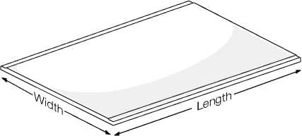
| |||||||||||||||
|
Table 4 | |||||||||||||||
| |||||||||||||||||
|
Table 5 | |||||||||||||||||
1.7 ACCESSORIES
|
Table 6 | ||||||||||||||||||||||||||||||||||||||||||
| ||||||||||||||||||||||||||||||||||||||||||
|
Table 7 | ||||||||||||||||||||||||||||||||||||
| ||||||||||||||||||||||||||||||||||||
|
HardieGroove Soffit Lining — Accessories / Tools Supplied by James Hardie | |||||
|
Accessories |
Description |
Product Code |
Accessories |
Description |
Product Code |
|
Soffit Scotia Mould (base and cap) 2400mm long, uPVC / white |
300916 |
^^^^^ |
Inseal 3259 1.5mm thick 50mm wide x 50m long, black compressible foam |
300767 | |
|
HardieBlade Saw Blade Ø184mm poly crystalline diamond blade, for fast, clean cutting of James Hardie fibre cement. |
300660 |
• |
James Hardie Base Coat Base compound for filling over screws. 4kg Pail 15kg Bag |
304490 304491 | |
|
^I^^^^ |
HardieDrive Screw s/s 316 30mm x 7g. 100 per jar For fastening to timber frames. |
300928 |
^%Hy |
Villadrive Screw 6g x 30mm For fastening to timber frames. 100/jar 5kg Box Collated/ 1000 |
300992 300993 300994 |
|
iT- |
HardieKnife™ Scoring tool for easy cutting. |
305926 | |||
|
Table 9 | ||||||||||||||||||||||||||||||||||||||||||||||||||||||
| ||||||||||||||||||||||||||||||||||||||||||||||||||||||
Components Not Supplied by James Hardie
|
James Hardie recommends the following products for use in conjunction with its eaves and soffit linings. James Hardie does not supply these products. Please contact component manufacturer for information on their warranties and further information on their products. | |||||||||||||||||||||||||||||||||||||||||||||||||||||||||||||||||
| |||||||||||||||||||||||||||||||||||||||||||||||||||||||||||||||||
2 Safe working practices
Use one of the following methods based on the required cutting rate:
BEST
-
• HardieKnife™
-
• Hand guillotine
-
• Fibreshear
BETTER
-
• Dust reducing circular saw equipped with HardieBlade™ Saw Blade and M Class extractor unit.
GOOD
-
• Dust reducing circular saw with HardieBlade™ Saw Blade
Working outdoors
A Make sure you work in a well ventilated area
it Position cutting station so wind will blow dust away from yourself and others in the working area
A Cut products with either a HardieKnife or fibre cement shears or, when not feasible, use a HardieBlade™ Saw Blade (or equivalent) and a dust-reducing circular saw attached to a M Class extractor unit
it When sawing, sanding, rebating, drilling or machining fibre cement products, always:
-
- Wear your P1 or P2 mask (correctly fitted in accordance with manufacturers’ instructions) and when others are close by, ask them to do the same
-
- If you are not clean shaven, then use a powered air respirator with a loose fitting head top.
-
- Wear safety glasses
-
- Wear hearing protection
-
- When others are close by, ask them to do the same.
Working indoors
-
■ 9 Never cut using a circular saw indoors
it Position cutting station in a well ventilated area
it Cut ONLY using a HardieKnife, hand guillotine or fibreshears (manual, electric or pneumatic)
it Make sure you clean up BUT never dry sweep. Always hose down with water/wet wipe or use an M Class extractor unit
IF CONCERN STILL EXISTS ABOUT EXPOSURE LEVELS
OR YOU DO NOT COMPLY WITH THE ABOVE PRACTICES, YOU SHOULD ALWAYS CONSULT A QUALIFIED INDUSTRIAL HYGIENIST.
STAY HEALTHY WHEN WORKING WITH BUILDING PRODUCTS CONTAINING CRYSTALINE SILICA
Crystalline Silica
What is it? Why and when is it a health hazard?
Crystalline Silica is
-
• Commonly known as sand or quartz
-
• Found in many building products e.g. concrete, bricks, grout, wallboard, ceramic tiles, and all fibre cement materials
Why is Crystalline Silica a health hazard?
-
• Silica can be breathed deep into the lungs when present in the air as a very fine (respirable) dust
-
• Exposure to silica dust without taking the appropriate safety measures to minimise the amount being breathed in, can lead to a potentially fatal lung disease – silicosis – and has also been linked with other diseases including cancer. Some studies suggest that smoking may increase these risks.
-
• The most hazardous dust is the dust you cannot see!
When is Crystalline Silica a health hazard?
-
• It’s dangerous to health if safety protocols to control dust are not followed when cutting, drilling or rebating a product containing crystalline silica.
-
• Products containing silica are harmless if intact (e.g. an un-cut sheet of wall board).
FAILURETO ADHERE TO OUR WARNINGS, SAFETY DATA SHEETS AND INSTALLATION INSTRUCTIONS WHEN WORKING WITH JAMES HARDIE PRODUCTS MAY LEAD TO SERIOUS PERSONAL INJURY OR DEATH.
AVOID BREATHING IN CRYSTALLINE SILICA DUST!
Safe working practices
■^ NEVER use a power saw indoors or in a poorly ventilated area
■p NEVER dry sweep
it ALWAYS use M Class extractor unit as a minimum and always hose down with water/wet wipe for clean up
■p NEVER use grinders
it ALWAYS use a circular sawblade specifically designed to minimise dust creation when cutting fibre cement – preferably a sawblade that carries the HardieBlade™ logo or one with at least equivalent performance.
I* ALWAYS follow tool manufacturers’ safety recommendations it ALWAYS expose only the minimum required depth of blade for the thickness of fibre cement to be cut
II
t ALWAYS wear an approved properly-fitted, approved dust mask (P1 or P2) or respirator
Working Instructions
-
• Refer to Recommended Safe Working Practices before starting any cutting or machining of product.
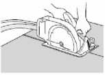
JAMES HARDIE IS NOT RESPONSIBLE FOR DAMAGE DUE TO IMPROPER STORAGE AND HANDLING.
TIPS FOR SAFE AND EASY HANDLING
Weatherboard products
-
■^ Do not lift planked products flat and in the middle
-
■^ Carry the products on the edge
it If only one person is carrying the product, hold it in the middle and spread arms apart to better support the product
it If two people are carrying the plank, hold it near each end and on edge
it Exercise care when handling weatherboard products to avoid damaging the edges/corners
Sheet products
it Carry with two people
it Hold near each end and on edge
li Exercise care when handling sheet products to avoid damaging the edges/corners
HardieBlade™ Saw Blade
The HardieBlade™ Saw Blade used with a dust-reducing saw is ideal for fast, clean cutting of James Hardie fibre cement products. A dust-reducing saw uses a dust deflector or a dust collector connected to a vacuum system. When sawing, clamp a straightedge to the sheet as a guide and run the saw base plate along the straight edge when making the cut.
|
Hole-Forming For smooth clean cut circular holes: • Mark the centre of the hole on the sheet. • Pre-drill a ‘pilot’ hole. | 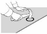 |
-
• Using the pilot hole as a guide, cut the hole
to the appropriate diameter with a hole saw fitted to a heavy duty electric drill.
For irregular holes:
-
• Small rectangular or circular holes can be cut by drilling a series of small holes around the perimeter of the hole then tapping out the waste piece from the sheet face.
-
• Tap carefully to avoid damage to sheets, ensuring that the sheet edges are properly supported.
STORAGE & DELIVERY
Keeping products and people safe
Off loading
it James Hardie products should be off-loaded carefully by hand or by forklift.
it James Hardie products should not be rolled or dumped off a truck during the delivery to the jobsite.
Storage
James Hardie products should be stored:
it in their original packaging
it under cover where possible or otherwise protected with a waterproof covering to keep products dry
it off the ground – either on a pallet or adequately supported on timber or other spacers
it flat so as to minimise bending
3 Framing
Timber framing must be in accordance with NZS 3604 Timber Frame Buildings. Specific design to NZS 3603 and AS/NZS 1170 can also be undertaken providing that:
Also refer to the Approved Document for NZBC Clause B2 ‘Durability’ and NZS 3602 (Timber and Wood-Based Products for use in Buildings) regarding timber treatment requirements and allowable moisture contents in timber for various components of the building. Also refer to the framing manufacturer’s literature for further guidance on the use of treated timber.
The figures in this brochure are drawn for timber framing. However, steel framing and furring channels can also be used. All metal framing centres are to be the same as specified for timber frame in this manual. Steel framing members must be fabricated from light-gauge sheet steel 0.55mm thick minimum to 1.6mm maximum. If heavier sections are used difficulties may be experienced in fixing the self-drilling, self-tapping fasteners. Refer to specific details for the minimum flange width requirements. Sheets must not be fixed directly to drawn steel or hot-rolled steel sections. These must first be battened out with ex 50mm-thick (40mm minimum) timber battens or light-gauge metal furring channels. Screw-fix 6mm or thicker sheets only. Screw fixings can be finished flush or sunk a maximum of 0.5mm below the sheet surface ready for filling. NOTE: The fasteners must not be over driven as will reduce the holding capaciity of the sheet.
For the framing set-out of up to 600mm-wide soffit refer to Figure 1. For the framing set-out of 601mm to 1200mm wide soffits refer to Figure 2.
When pre-finished steel fascia/gutters are used the soffit edge must be supported 4mm minimum into fascia recess, similar to Figure 10. Ribbon board to be continuous for product fixing. NOTE: Because of the limited fascia groove available with some metal fascias a supporting ribbon board will be required with fixings at 300mm centres maximum. Pre-finished soffits can distort due to surface tension when adequate edge support is not provided. |
Table 11 Eaves Lining Framing Centres
*HardieFlex Sheet 6mm or Villaboard Lining 6mm must be used in EH Wind Zone with soffit bearers maximum 600mm centres.
| ||||||||||||||||||||||||||||||||||||||||||||||||||||||||||||||||||||||||||||||||||||
|
Figure 2: Eaves and soffits 601mm to 1200mm |
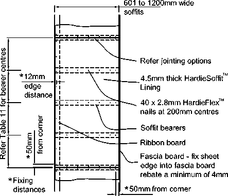 |
-
1. HardieFlex™ nails are the usual fixing method for HardieSoffit™ Lining. The fastfix method can also be used as an alternative.
-
2. When fastfix fastenings are used refer to Table 7 and Figure 8 and 9.
NOTE: Because of the limited fascia groove available with some metal fascias a supporting ribbon board will be required with fixings at 300mm centres maximum. Pre-finished soffits can distort due to surface tension when adequate edge support is not provided.
-
3.4 BATTEN REQUIREMENTS
Battens are required when sheets are fixed over:
-
• Gypsum board exceeding 20mm in thickness
-
• Softboard, polystyrene or similar
-
• Concrete, masonry block or brick.
Timber battening is to be a minimum of 35mm deep x 40mm wide to achieve adequate sheet nail penetration.
Steel battens must be minimum 0.55mm thick, 23mm deep and have a bearing surface of 38mm min. Battens must be galvanised to meet the durability requirements of the New Zealand Building Code (NZBC) and fixed to manufacturer’s specifications. All battening centres and sheet fixing is to be strictly in accordance with the framing and fixing required by this manual. Care must be taken to ensure the battens are packed and aligned to give a true even surface for the sheets to be fixed. Check the face of the battens with a long straight-edge before fixing sheets.
-
3.5 SKILLION ROOF DESIGN
When installing soffit linings direct to the under side of skillion roof framing, ensure that sufficient ventilation has been provided within the roof space. The temperatures within these smaller roof spaces can reach very high levels in certain conditions and this can cause cracking in flush stopped joints due to excessive movement in roof framing. Therefore the framing in skillion soffits and ceilings need a specific engineering design consideration.
General design guide for a narrow strip of flash stopped soffits is to provide a control joint at 4.8m centres.
General design guide for large flash stopped soffits is to provide control joints at 4.8m x 3.6m in either direction when fixing to this type of framing.
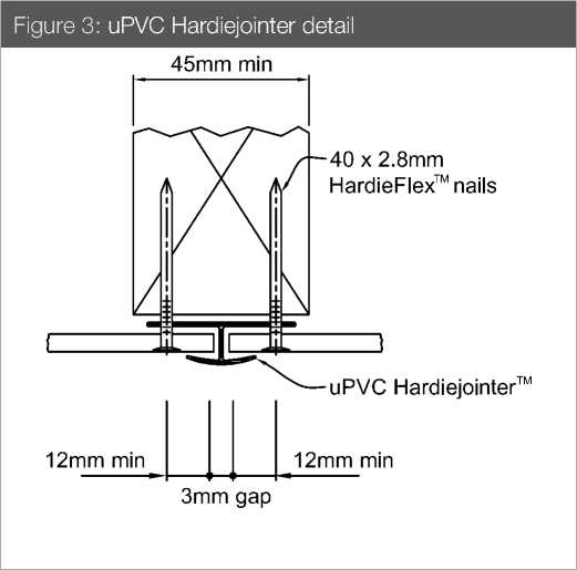
4 Jointing options
-
• All soffit lining sheet edges must be supported by framing and/or a fascia board.
HARDIESOFFIT LINING
-
• Refer to Figure 3 for uPVC Hardiejointer detail
-
• Refer to Figure 5 for express joint detail
-
• Refer to Figure 9 for two-way uPVC jointer
HARDIEFLEX EAVES LINING
-
• Refer to Figure 3 for uPVC Hardiejointer detail
-
• Refer to Figure 4 for butt joint detail
-
• Refer to Figure 5 for express joint detail
-
• Refer to Figure 9 for two-way uPVC jointer
ECLIPSA EAVES LINING
-
• Refer to Figure 3 for uPVC Hardiejointer detail
-
• Refer to Figure 8 for Fastfix Fasteners fixing detail. Use a 6mm diameter masonry drill bit to drill a hole and fix fasteners
-
• Refer to Figure 9 for Two-way uPVC Jointer
HARDIEGROOVE SOFFIT LINING
-
• Sheets have half groove along the long edges for butt jointing
-
• Sheets to have chamfer formed on site along the short edge for butt jointing
VILLABOARD SOFFIT LINING
-
• Refer to Figure 6 for flush joint details. Refer to Section 5.5 for flush jointing
-
• Refer to Figure 3 for uPVC Hardiejointer detail
-
• Refer to Figure 4 for butt joint detail
-
• Refer to Figure 5 for express joint detail
-
• Refer to Figure 7 for sealant joint detail
|
Figure 5: Expressed joint detail |
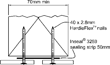 |
| |||||
|
10mm max gap |
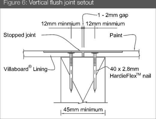
Figure 4: Butt joint detail
45mm min
|
Figure 7: Sealant joint detail |
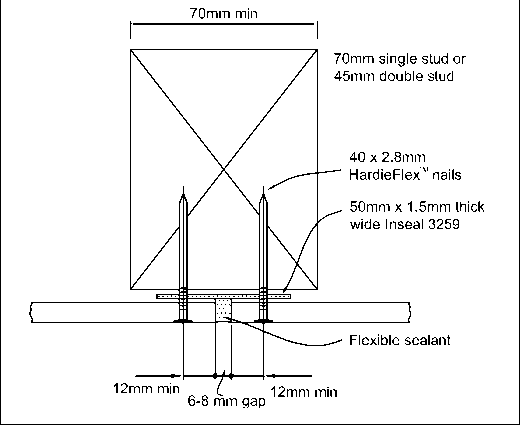 |
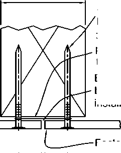
40 x 2.8mm HardieFlex™ nails
30mm wide polypropylene or flashing tape
Edge of board must be primed prior to installation
Factory edge
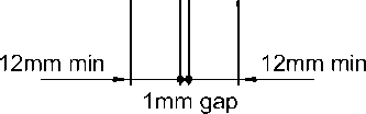
|
Figure 8: Fastfix fastener fixing detail Figure 10: Cladding detail with scotia mould |
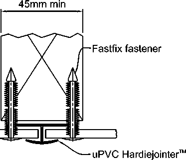 |
15mm15mm
2 - 3mm gap
Note: Use a 6mm drill bit for drilling holes in sheet for fixing Fastfix fasteners.
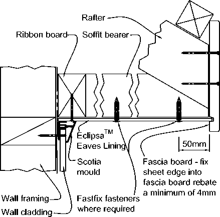 |
|
Figure 11: Brick veneer detail with scotia mould |
|
Figure 9: Two-way uPVC jointer 45mm min |
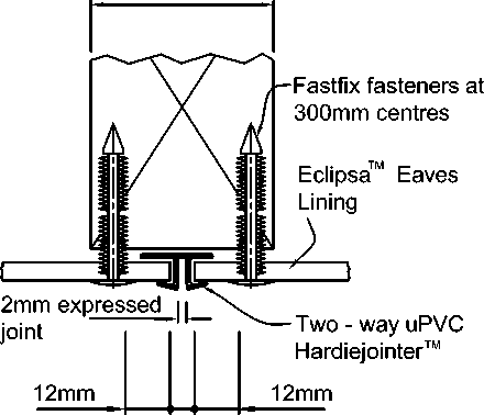 |
|
6mm gap |
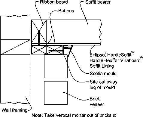 |
|
provide ventilation as required by NZS 3604 |
Note: Use a 6mm drill bit for drilling holes in sheet for fixing Fastfix fasteners.
5 Installation
|
This installation manual covers the use of James Hardie Eaves and Soffits for buildings within the scope of NZS 3604. For all other buildings specific engineering design is required.
Refer to Table 11 and Figure 1 and 2 regarding nail fixing centres, for framing and types of fasteners. The eaves/soffits must be sealed against claddings to minimise moisture ingress behind the claddings. The roof must have been installed before installing the soffits linings. Where the soffits are sloping upwards away from the wall, a mechanical flashing must be provided in the soffit to wall junction. The flashing is fixed under soffit lining and laps over the face of cladding by 35mm minimum Refer to Figure 27 - Figure 30.
All soffit linings must either be installed with a grooved fascia, refer Figure 10, or with exterior cladding which forms a drip edge below the soffit lining by 15mm minimum. Soffit linings are generally fitted into the recess formed in fascia board to form the drip edge.
HardieFlex Eaves Lining and Villaboard Soffit Lining are suitable for use in structural ceiling diaphragms as per NZS 3604. Refer to the James Hardie Bracing Design Manual.
HardieFlex Eaves Lining and Villaboard Soffit Lining can be used for curved applications. The minimum bending radii are shown below.
|
For full details refer to the James Hardie Fire and Acoustic Design Manual or Ask James Hardie on 0800 808 868.
Fasteners used in external applications must meet the minimum durability requirements of the NZBC. NZS 3604 specifies the requirements for fixing’s material to be used in relation to the exposure conditions and are summarised in Table 14.
For framing and fixing schedules refer to Section 3. All sheet edges are to be supported by framing or a fascia board. Fixings are to be at 200mm centres to all framing (refer Figures 1 and 2). HardieSoffit Lining up to a max. width of 600mm can be jointed up to a maximum 150mm off the ceiling/soffit batten when using uPVC jointers. NOTES
For framing and fixing schedules refer to Section 3. All sheet edges are to be supported by framing or a fascia board. Fixings are to be at 200mm centres to all framing (refer Figures 1 and 2). NOTES
| ||||||||||||||||||||||||||||||||||||||||
-
5.5 HARDIEGROOVE SOFFIT LINING FIXING METHOD
For framing and fixing schedules refer to Section 3.
The recommended fixing methods are combined nail and adhesive or screw and adhesive. (Refer Figure 12).
To achieve a concealed joint, butt the long edges together (half grooved). (Refer Figure 13).
|
Figure 13: Sheet edge and groove detail |
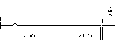 |
|
100mm centres |
|
Figure 12: Nail or screw and adhesive fixing |
Note: Sheets are grooved along the length of the sheet. |
Fascia board 7.5mm HardieGroove™ Soffit Lining Daubs of adhesive at 300mm centres Double nails or screws 50mm apart to centre of sheet Ribbon board 40 x 2.8mm HardieFlex™ nails or Villadrive screws at 200mm centres Butt joint with 1 - 2mm gap NOTES
Nails must be finished flush with the sheet surface. Screw heads can be finished 0.5mm below the sheet surface and stopped. In steel framing the fasteners should be driven as close as possible to the stud corners to avoid deflection of the stud flange |
Once the sheets are in place, fill over all driven fixings with James Hardie Base Coat to the required level of finish.
|
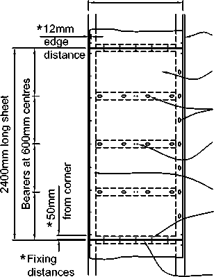
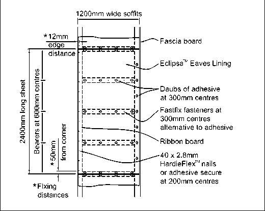
Fastfix fasteners (38mm long) can be used as an alternative fixing for prefinished soffit and ceiling systems in conjunction with adhesives. Drill a 6mm-diameter hole through the sheet and framing to insert the Fastfix fastener. In timber the hole must be 40mm deep.
The recommended masking tape for use with Eclipsa Eaves Lining is 3M Scotch Blue I8E 2090 or Sellotape 5855 longlife. This tape can only be left on the Eclipsa Eaves Lining for maximum 7 days, otherwise tape removal may cause paint loss.
(SOFFITS UP TO 1200mm) Villaboard Lining 6mm-thick is used when a smooth sanded sheet is required to achieve a painted flush finish. Refer to the framing fixing schedule Section 3 Table 11, Figures 1 and 2, and finishing schedules on Section 6. Refer to the flush jointing procedures, Section 6. Fix with either HardieFlex nails 40 x 2.8mm (galvanised or 316 stainless steel), Villadrive sood screws or HardieDrive stainless steel 30mm x 7g wood screws Screws finished 0.5mm below surface, Nails finished flush with surface. Figure 15: Nail/screw and adhesive fixed soffit 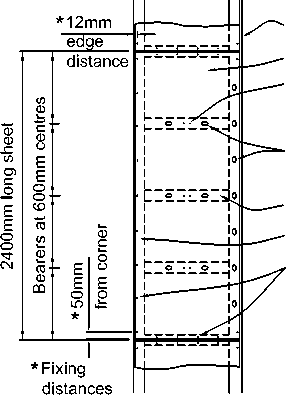
Fascia board Villaboard® Lining Double nails or screws 50mm apart to centre of sheet Daubs of adhesive at 300mm centres Soffit bearers Ribbon board 40 x 2.8mm HardieFlex™ nails or Villadrive screws at 200mm centres |
Control joints are required in long runs of Villaboard Lining soffits/ ceilings to accommodate structural movement. Control joints must also be provided where the soffits change in direction, change in level, where there is a construction joint in framing or where the soffits continue into passage ways etc. See Table 15 for maximum control joint spacing and Figure 17 for a typical control joint detail.
Villaboard Soffit Lining is suitable for:
| |||||||||||||
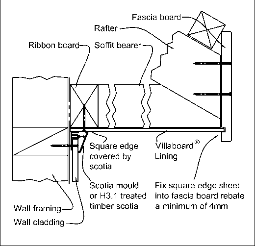
-
• Alternatively sheets can be fixed with nails / screws only at 200mm centres at sheet edges and 250mm centres at intermediate framing
-
5.7.3 Narrow-Strip Flush-Jointed Soffits And Ceilings
In these applications sheets must be jointed on the framing as shown in Figures 1 and 2. Control joints, as shown in
Figure 17, must be located at a distance as specified in Table 15.
Sheets must not be fixed to the bottom cord of roof trusses.
|
Figure 18: Ceiling layout |
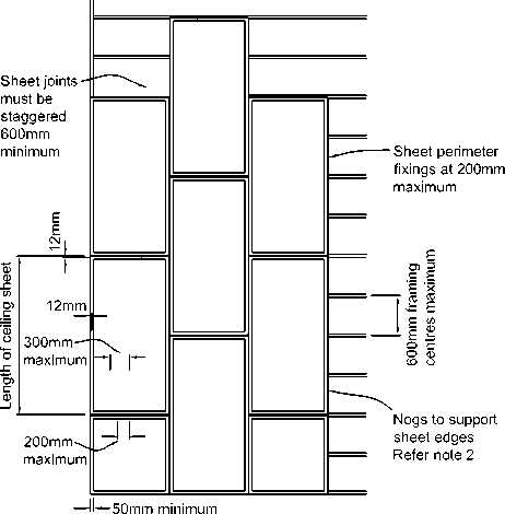 |
|
at corners |
|
Figure 17: Control joint |
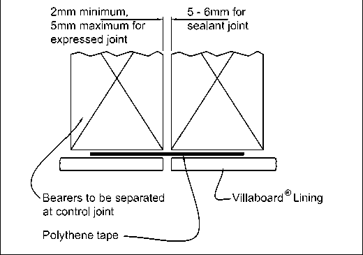 |
|
NOTE Refer Section 5.7.3 for skillion roof design.
For standard commercial soffits and ceilings, framing must be at 600mm maximum centres and 6mm thick Villaboard Soffit Lining can be used. For high-impact areas, heavy-use commercial areas, and high-wind areas, framing at 600mm maximum centres and 9mm thick Villaboard Soffit Lining should be used. Sheets must not be fixed to the bottom cord of roof trusses. Timber or steel ceiling battens must be fixed to the underside of the roof truss. Sheets must be laid in an offset pattern so that adjacent end joints do not coincide. Timber ceiling battens must comply with the requirements of NZS 3604 or the specific engineering design. Steel ceiling battens must be a minimum of 37mm wide x 23mm deep x 0.55mm thick and have a bearing surface of 37mm minimum. Battens must be galvanised steel (275 g/m2 zinc coating), have a suitable coating to meet the durability requirements and be fixed to the manufacturer’s specifications. Refer to the flush-jointing and finishing procedures on Section 6. For specific engineering design projects consideration must be given to framing deflections expected due to loadings and appropriate selection of sheet jointing method must be made. NOTE
|
The ceilings must be divided into bays not exceeding 7.2 x 4.8m. To permit movement, control joints must be formed at the perimeter of each bay (refer Figures 19, 20, 21 and 22) and at the junction of large ceilings with narrow passage strips or where there is a change in direction (also refer Figures 20 and 21). Each bay must be independent of adjacent bays and the surrounding building structure. When the ceilings or soffits contain sloping areas then control joint centres must be reduced to coincide with the slope change lines (refer Figure 22). Framing members (to which the sheet is fixed) must not continue across this control joint. Sheets shall be fixed across the ceiling joists or ceiling battens (refer Figures 24 and 25). Figures 20 and 21 show control joints with the battens running in the same direction as the sheet joint. When these ceilings are wider than one sheet width the sheets can be fixed to the framing provided the control joints are placed to limit the bay size to 7.2m x 4.8m maximum. |
Figure 21: Timber control joint detail
|
Figure 19: Control joint layout |
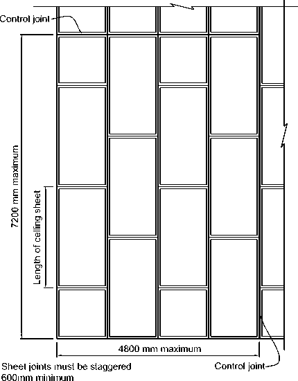 |
|
Gap 10mm minimum 12mm maximum Bearers Acoustic sealant (optional) |
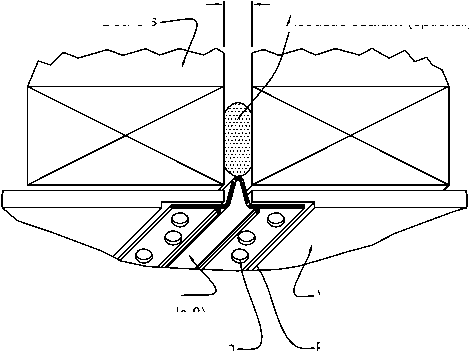 |
|
Villaboard® Lining Fix at 200mm centres with 2.8mm HardieFlex™ nail Flush over then remove protective tape |
uPVC control joint section (refer Table 8)
|
Figure 20: Steel ceiling batten control joint detail |
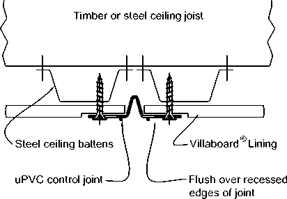 |
|
Figure 22: Directional changes to soffits and ceilings — control joint Villaboard® Lining | |
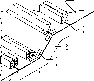 |
Control joint (refer Figure 21) |
|
4200mm maximium between control joints Steel or PVC tie at 300mm centres Two fixings into each framing member each side of tie | |
Control joint (refer Figure 21)
Note: Tie fixings to be 40 x 2.8mm HardieFlex™ nails.
|
Figure 23: Skillion Roof/Ceiling |
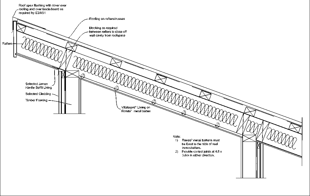 |
When installing soffit linings direct to skillion roof framing ensure that sufficient ventilation has been provided within the roof space. The temperatures within these smaller roof spaces can reach very high levels in certain conditions and this can cause cracking in flush stopped joints due to excessive movement in framing. Therefore the framing in skillion soffits and ceiling need a static engineering design consideration. General design guide is to provide control joints at 4.8m x 3.6m in either direction when fixing to this type of framing.
A smooth surface finish is obtained by minimising the visible sheet fixings. For painted finishes the combined nail or screw and adhesive method gives this superior finish (refer Figure 24). Fix at 200mm centres down each sheet end with edge fixings in each joist or batten. Double-fix in the centre of each joist or batten. Do not place nails or screws within 100mm of adhesive daubs. Daubs of wallboard adhesive 25mm diameter and 15mm thick must be applied to the intermediate joists or battens at 250mm centres (refer Figure 24). When nogs are not installed for perimeter support, the unsupported edges between ceiling joists or battens must be supported with back blocking using a 300-400mm wide Villaboard Lining strip adhered to rear face and centred between framing. |
NOTES
|
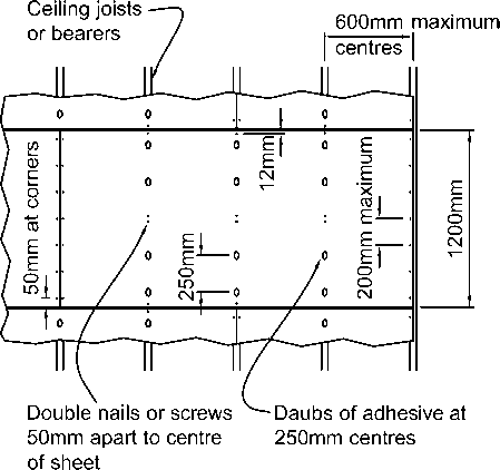
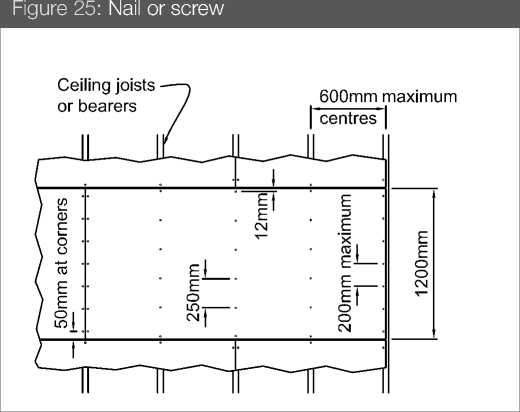
For an alternative nail or screw-fixing method, fasteners are to be driven along the sheet perimeter at 200mm centres and along intermediate ceiling battens at 250mm centres (refer Figure 25). When nogs are not installed for perimeter support, the unsupported edges between ceiling joists or battens must be supported with back blocking using a 300-400mm wide Villaboard Lining strip adhered to rear face and centred across ceiling joists.
Soffit sheeting must be free to move independently from the building element it abuts with. This is critical for flush-jointed sheeting, otherwise cracking at the joint may occur.
Square-edge Villaboard Lining is used for butt-joint; expressed-joint or uPVC-jointed ceilings. |
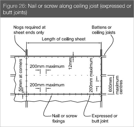
May be used as soffit with expressed joint when installed as per Figure 5 and fixings as per Villaboard Soffit Lining.
For fixing Villaboard Lining and HardieGroove Lining in internal swimming pool areas;
Only stainless steel fasteners must be used.
|
-
5.11 SPECIAL DETAILS
|
Figure 27: Sloping soffit and direct fixed flatsheet cladding |
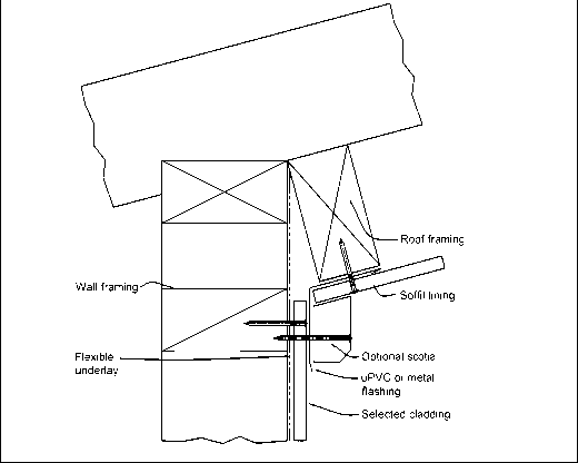 |
|
Figure 29: Sloping soffit and direct fixed weatherboard cladding |
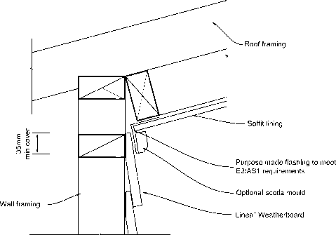 |
|
Figure 28: Sloping soffit and cavity fixed flatsheet cladding |
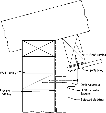 |
|
Figure 30: Sloping soffit and cavity fixed weatherboard cladding |
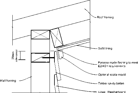 |
-
6 Villaboard Joint Stopping
|
FOR VILLABOARD LINING
Villaboard Soffit Lining is finished with paint complying with parts 7, 8, 9 and 10 of AS 3730. The application and maintenance must be in accordance with the manufacturer’s specifications. NOTE: Before flush stopping sheet edges must be sealed with Multiplast resin, water proofing admixture or other similar products.
In some instances, due to glancing light, set joints may be noticeable in Villaboard Lining walls, especially where paint finishes have a high gloss level. Work closely with your builder or designer to minimise this. |
Artificial lighting needs to be considered in relation to soffits. Where glancing light is an issue its effect can be lessened by:
Different levels of finishes are typically specified for different applications. Higher levels of finishes are used to address the glancing light issues with painted Villaboard Soffit Lining referred to above. A description of the various levels of finishes and the jointing/coating requirements can be found in Table 16. |
|
Table 16 | ||||||||||||||||||||||||||||||||
| ||||||||||||||||||||||||||||||||
|
*Reference: AS/NZS 2589.1: ‘Gypsum lining in residential and light commercial construction — Application and finishing. Part 1: Gypsum plasterboard’ | ||||||||||||||||||||||||||||||||
Prior to application of paint finishes, remove any residual sanding dust and ensure the surface is suitable for paint application. Always follow the paint manufacturer’s recommendations for paint suitability, mixing and application. NOTES
|
MIXING INSTRUCTIONS Table 17 James Hardie Base Coat Mixing Instructions 
Step 1 First, add 1 part of clean water into bucket. Then add 2½ parts James Hardie Base Coat powder Allow to soak for 1 minute.
|

Villaboard Soffit Lining joints are set with James Hardie jointing compounds reinforced with perforated paper tape. Recessed edge sheet joints require joint setting by using the jointing products outlined. The performance of joints is the responsibility of the installer, as this is governed by the installation practices and the standard of workmanship applied. However, James Hardie considers that the recommendations provided in Table 16 describe best practice to reduce the risk of joint cracking or other problems. There are various factors that can affect the performance of jointing compounds on edge recessed fibre cement substrates. These factors include the framing, movement, installation quality, vibrations, moisture, humidity, temperature, etc. To achieve satisfactory joint performance these factors need to be carefully considered and understood by the installer and designer when positioning joints and selecting jointing compounds. Furthermore, it is important that the jointing compound used has the physical attributes required to perform considering these factors. James Hardie compounds have been specifically developed for use with Villaboard Soffit Lining. In addition, provision for movement needs to be made by the installation of control joints. Refer to clasue 5.7.1. COMPOUND COVERAGE 1kg of Base Coat will provide approximately 5 lm of standard joints. 1kg of Top Coat will provide approximately 5.6 lm of standard joints. NOTE Follow the mixing instructions carefully when mixing James Hardie Base Coat and Top Coat. |

Step 2 Mix for 1½ – 2 minutes using paint mixer or equivalent. (approximately 2500-3000rpm) James Hardie Base Coat is NOT like the plaster based compounds. Initial mixing will indicate a dry mix and further mixing WITHOUT further addition of water will deliver the ideal workable paste. Warning: Inadequate or over mixing can lead to poor workability and can cause performance issues. Do not hand mix. Step 3 The mix at this stage should be consistently smooth. Based on the environmental conditions (i.e. temperature and humidity) you may add maximum of 25ml of water per 1Kg of base coat powder in the mix at this stage to adjust workability. Mix it well. (Note: Adding excess water than the recommendation may delay the drying of base coat and may cause joint cracking due to excessive shrinkage.) Mix should be glossy and smooth. There should be no lumps in the mix. Important Notes:
|


Product Life:
James Hardie Base Coat has a shelf life of 12 months in unopened bags when stored in a cool dry place.
James Hardie Base Coat has a bag life of 1 month if opened bags are resealed and stored in a cool dry place.
Step 1 — Preparation Ensure that the recesses are clean and free of dust and contaminants. Sheet edges must be sealed with Multiplast resin, water proofing admixture or other similar products. If working conditions are hot and dry, dampen the area around the joint prior to working. 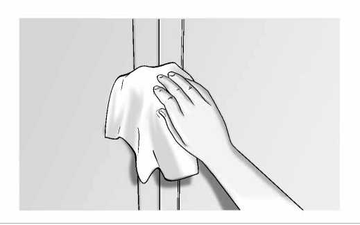
NOTE The jointing method shown below provides a Level 4 finish. For more information about this and other finishes refer to page 21. Step 2 — First Coat Apply James Hardie Base Coat to fill the recess with a 150mm broad knife.  |
Step 3 — Embed Tape Firmly embed the perforated paper tape centrally into the joint using a 50mm broad knife. Ensure that there are no voids under the tape and remove excess compounds. 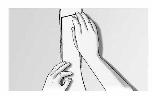 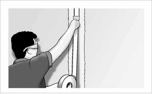
Step 4 — Thin Layer Immediately cover tape with a thin layer of James Hardie Base Coat applied with a 150mm broadknife. 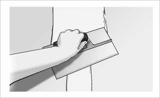 |
NOTE
Steps 5, 6 and 7 are only required for paint and wall paper finish.
-
7 Finishing
|
Step 5 — Second Coat When the first coat is fully dry, use a 200mm wide second coat trowel to apply the James Hardie Base Coat. Apply this coat approximately 180mm wide, laid down over the recess and feather the edges. 
Step 6 — Finishing Coat Ensure the second coat is fully dry. Using a finishing trowel, apply a coat of James Hardie Top Coat 280mm wide centrally over the joint and feather out the edges. Allow to dry fully before sanding. Sand with a 180 grit sand paper to achieve a smooth finish for painting. 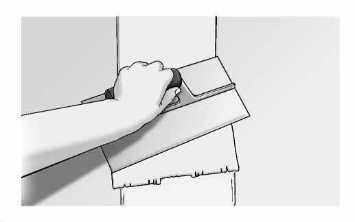 |
HardieSoffit Lining, HardieFlex Eaves Lining, Villaboard Soffit Lining and HardieGroove Soffit Lining sheets are to have a minimum of two coats of acrylic paint applied after fixing in order to meet the requirements of the NZBC. All sheets must be coated within 3 months of installation. Use quality 100% acrylic paints. Economy paints are not recommended because generally they are less well bound, less moisture resistant and more prone to mould growth. In all cases the manufacturer’s specification for the selected paint must be followed. Note that some paints require an undercoat before applying finish coats. Damp, shady situations, proximity to bush, agricultural paddocks or seaspray environments may induce an extra tendency to mould growth. Use mould-inhibiting and alkaline-resistant undercoats and consult the paint manufacturer for details of maximum mouldresistant paints. Before painting, remove any surface grime or other contaminants and ensure the HardieSoffit Lining, HardieFlex Eaves Lining, Villaboard Soffit Lining and HardieGroove Soffit Lining is dry. Paint must not be applied when the air temperature is below 10˚C. When using uPVC moulds avoid dark colours (paints must have light reflection of 40% or more) as excessive movement may cause buckling of the uPVC when exposed to direct sunlight. Enamel-based paints can be used, utilising a three-coat system. For full details apply to the selected paint manufacturer before commencing the work. |
Step 7 — Fastener Heads
Apply a finishing coat of James Hardie Base Coat to fastener heads, feathering out the edges. Allow to fully dry before sanding.
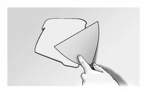
8 Product 9 Maintenance information
HardieSoffit Lining, HardieFlex Eaves Lining, Eclipsa Eaves Lining, HardieGroove Soffit Lining and Villaboard Soffit Lining are a cellulose fibre reinforced cement building product. The basic composition is Portland cement, ground sand, cellulose fibre and water. HardieSoffit Lining, HardieFlex Eaves Lining, Eclipsa Eaves Lining, HardieGroove Soffit Lining and Villaboard Soffit Lining is manufactured to AS/NZS 2908.2 ‘Cellulose-Cement Products Part 2: Flat Sheets’ (ISO 8336 ‘Fibre Cement Flat Sheets’). James Hardie New Zealand Limited is an ISO 9001 ‘Telarc’ certified manufacturer. HardieSoffit Lining, HardieFlex Eaves Lining, Eclipsa Eaves Lining, HardieGroove Soffit Lining and Villaboard Soffit Lining are classified Type A, Category 3 in accordance with AS/NZS 2908.2 ‘Cellulose-Cement Products’. For Safety Data Sheets (SDS) visit www.jameshardie.co.nz or Ask James Hardie on 0800 808 868.
Resistance to moisture/rotting HardieSoffit Lining, HardieFlex Eaves Lining, Eclipsa Eaves Lining, HardieGroove Soffit Lining and Villaboard Soffit Lining has demonstrated resistance to permanent moisture induced deterioration (rotting) and has passed the following tests in accordance with AS/NZS 2908.2:
HardieSoffit Lining, HardieFlex Eaves Lining, Eclipsa Eaves Lining, HardieGroove Soffit Lining and Villaboard Soffit Lining must be paint finished within 90 days of their installation. Refer to the paint manufacturer for paint suitability, mixing and application.
HardieGroove Lining and Villaboard Lining have a ‘Group Number’ classification of 1 – S as per the requirements of Clause C of the NZBC. |
It is the responsibility of the specifier to determine normal maintenance requirements for eaves and soffits to comply with NZBC Acceptable Solution B2/AS1. The extent and nature of maintenance will depend on the geographical location and exposure of the building. As a guide, it is recommended that basic normal maintenance tasks shall include but not be limited to:
|
All James Hardie eaves and soffit linings come with a 15 year product warranty. Pre-finished products such as Eclipsa Eaves Lining come with a 10 year coating warranty and 15 year warranty on the base sheet. All accessories supplied by James Hardie are warranted for a period of 15 years. For full warranty details visit www.jameshardie.co.nz or Ask James Hardie on 0800 808 868.
Disclaimer: The recommendations in James Hardie’s literature are based on good building practice, but are not an exhaustive statement of all relevant information and are subject to conditions (c), (d), (f) and (g) in each products warranty under “Conditions of Warranty”. James Hardie has tested the performance of the HardieSoffit™ Lining, HardieFlex™ Eaves Lining, Eclipsa™ Eaves Lining, HardieGroove™ Lining and Villaboard™ Soffit Lining, and when installed in accordance with the HardieSoffit™ Lining, HardieFlex™ Eaves Lining, Eclipsa™ Eaves Lining, HardieGroove™ Lining and Villaboard™ Soffit Lining installation manual, in accordance with the standards and verification methods required by the New Zealand Building Code (NZBC) and those test results demonstrate the product complies with the performance criteria established by the NZBC. However, as the successful performance of the relevant system depends on numerous factors outside the control of James Hardie (e.g. quality of workmanship and design) James Hardie shall not be liable for the recommendations made in its literature and the performance of the relevant system, including its suitability for any purpose or ability to satisfy the relevant provisions of the NZBC, regulations and standards, as it is the responsibility of the building designer to ensure that the details and recommendations provided in the relevant James Hardie installation manual are suitable for the intended project and that specific design is conducted where appropriate.
Copyright April 2019. © James Hardie New Zealand Limited. TM and ® denotes a Trademark or Registered Mark owned by James Hardie Technology Limited.
James Hardie
Copyright April 2019. © James Hardie New Zealand Limited. TM and ® denotes a Trademark or Registered Mark owned by James Hardie Technology Limited
Villaboard
SOFFIT LINING
TM
James Hardie New Zealand Limited (“James Hardie”) warrants for a period of 15 years from the date of purchase that the Villaboard™ Soffit Lining (the “Product”), will be free from defects due to defective factory workmanship or materials and, subject to compliance with the conditions below, will be resistant to cracking, rotting, fire and damage from termite attacks to the extent set out in James Hardie’s relevant published literature current at the time of installation. James Hardie warrants for a period of 15 years from the date of purchase that the accessories supplied by James Hardie will be free from defects due to defective factory workmanship or materials.
Nothing in this document shall exclude or modify any legal rights a customer may have under the Consumer Guarantees Act or otherwise which cannot be excluded or modified at law.
CONDITIONS OF WARRANTY:
The warranty is strictly subject to the following conditions:
-
a) James Hardie will not be liable for breach of warranty unless the claimant provides proof of purchase and makes a written claim either within 30 days after the defect would have become reasonably apparent or, if the defect was reasonably apparent prior to installation, then the claim must be made prior to installation;
-
b) this warranty is not transferable;
-
c) the Product must be installed and maintained strictly in accordance with the relevant James Hardie literature current at the time of installation and must be installed in conjunction with the components or products specified in the literature. Further, all other products, including coating and jointing systems, applied to or used in conjunction with the Product must be applied or installed and maintained strictly in accordance with the relevant manufacturer’s instructions and good trade practice;
-
d) the project must be designed and constructed in strict compliance with all relevant provisions of the current New Zealand Building Code (“NZBC”), regulations and standards;
-
e) the claimant’s sole remedy for breach of warranty is (at James Hardie’s option) that James Hardie will either supply replacement product, rectify the affected product or pay for the cost of the replacement or rectification of the affected product;
-
f) James Hardie will not be liable for any losses or damages (whether direct or indirect) including property damage or personal injury, consequential loss, economic loss or loss of profits, arising in contract or negligence or howsoever arising. Without limiting the foregoing James Hardie will not be liable for any claims, damages or defects arising from or in any way attributable to poor workmanship, poor design or detailing, settlement or structural movement and/or movement of materials to which the Product is attached, incorrect design of the structure, acts of God including but not limited to earthquakes, cyclones, floods or other severe weather conditions or unusual climatic conditions, efflorescence or performance of paint/coatings applied to the Product, normal wear and tear, growth of mould, mildew, fungi, bacteria, or any organism on any Product surface or Product (whether on the exposed or unexposed surfaces);
-
g) all warranties, conditions, liabilities and obligations other than those specified in this warranty are excluded to the fullest extent allowed by law;
-
h) if meeting a claim under this warranty involves re-coating of Products, there may be slight colour differences between the original and replacement Products due to the effects of weathering and variations in materials over time.
Disclaimer: The recommendations in James Hardie’s literature are based on good building practice, but are not an exhaustive statement of all relevant information and are subject to conditions (c), (d), (f) and (g) above. James Hardie has tested the performance of the Villaboard™ Soffit Lining when installed in accordance with the Villaboard™ Soffit Lining Installation Manual, in accordance with the standards and verification methods required by the NZBC and those test results demonstrate the product complies with the performance criteria established by the NZBC. However, as the successful performance of the relevant system depends on numerous factors outside the control of James Hardie (e.g. quality of workmanship and design) James Hardie shall not be liable for the recommendations made in its literature and the performance of the relevant system, including its suitability for any purpose or ability to satisfy the relevant provisions of the NZBC, regulations and standards, as it is the responsibility of the building designer to ensure that the details and recommendations provided in the relevant James Hardie installation manual are suitable for the intended project and that specific design is conducted where appropriate.
Copyright April 2019. © James Hardie New Zealand Limited. TM and ® denotes a Trademark or Registered Mark owned by James Hardie Technology Limited.
4424RL RoofLogic Ultratherm Xtreme Fibertite Roofing System

RoofLogic Limited +64 04 4757663 sophia@rooflogic.co.nz www.rooflogic.co.nz/
SUPPORTING DOCUMENTS
Branz Appraisal 884 FiberTite Roofing Systems
Ref 10710. Uploaded 17 May 2022
Purpose: Performance

BRANZ Appraised
Appraisal No. 884 [2020]
FIBERTITE ROOFING SYSTEMS
Appraisal No. 884 (2020)
This Appraisal replaces BRANZ
Appraisal No. 884 (2015)
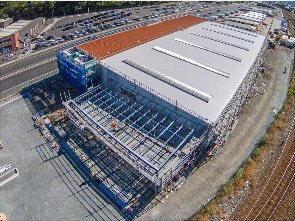
BRANZ Appraisals
Technical Assessments of products for building and construction.
// Seaman Corporation
Seaman Corporation
1000 Venture Blvd
Wooster
Ohio 44691
Web: www.fibertite.com
Marketed By:
ROOFLOGIC
INT€LUG6NT ROOFING SOLUTIONS


BRANZ
BRANZ
1222 Moonshine Rd, RD1, Porirua 5381 Private Bag 50 908
Porirua 5240, New Zealand
Tel: 04 237 1170
branz.co.nz

Product
1.1 FiberTite Roofing Systems are fully bonded, ketone ethylene ester (KEE) based waterproofing membranes for roofs and decks.
Scope
-
2.1 FiberTite Roofing Systems have been appraised as roof and deck waterproofing membranes on buildings within the following scope:
-
the scope limitations of NZBC Acceptable Solution E2/AS1, Paragraph 1.1; or,
-
the scope of limitations of NZBC Acceptable Solution E2/AS1, Paragraph 1.1 with regards to building height and floor plan area when subject to specific structural design; and,
-
with substrates of plywood or suspended concrete slab; and,
-
with minimum falls for roofs of 1:30 and decks of 1:40; and,
-
with deck size limited to 40 m2; and,
-
situated in NZS 3604 Wind Zones, up to, and including Extra High.
-
2.2 FiberTite Roofing Systems have also been appraised as roof and deck waterproofing membranes on buildings within the following scope:
-
subject to specific structural and weathertightness design and,
-
with substrates of plywood or suspended concrete slab; and,
-
situated in specific design wind pressures up to a maximum design differential ultimate limit state (ULS) of 6 kPa; and,
-
with the weathertightness design of junctions for each specific structure being the responsibility of the building designer.
-
2.3 Roofs and decks waterproofed with FiberTite Roofing Systems must be designed and constructed in accordance with the following limitations:
-
nominally flat or pitched roofs and decks constructed to drain water to gutters and drainage outlets complying with the NZBC; and,
-
with no steps within the deck level, no integral roof gardens and no downpipes directly discharging to the deck; and,
-
with the deck membranes continually protected from physical damage by a pedestal protection system.
-
2.4 The design and construction of the substrate and movement and control joints is specific to each building, and therefore is the responsibility of the building designer and building contractor and is outside the scope of this Appraisal.
-
2.5 The membranes must be installed by Rooflogic approved applicators.
BRANZ Appraised
Appraisal No. 884 [2020]
Building Regulations
New Zealand Building Code (NZBC)
-
3.1 In the opinion of BRANZ, FiberTite Roofing Systems, if designed, used, installed and maintained in accordance with the statements and conditions of this Appraisal, will meet the following provisions of the NZBC:
Clause B2 DURABILITY: Performance B2.3.1 (b), 15 years. FiberTite Roofing Systems meet this requirement. See Paragraphs 10.1 and 10.2.
Clause E2 EXTERNAL MOISTURE: Performance E2.3.1 and E2.3.2. FiberTite Roofing Systems meet these requirements. See Paragraphs 13.1 - 13.9.
Clause F2 HAZARDOUS BUILDING MATERIALS: Performance F2.3.1. FiberTite Roofing Systems meet this requirement and will not present a health hazard to people.
Technical Specification
-
4.1 Materials supplied by Seaman Corporation are as follows:
-
36 mil FiberTite - is a ketone ethylene ester based membrane, reinforced with 840 x 1,000 denier weft reinforced polyester knit fabric. It is supplied as a 0.91 mm thick light grey sheet membrane in rolls either 1.88 m or 2.54 m wide and 30.48 m long.
-
36 mil FiberTite-FB - is a ketone ethylene ester based membrane, reinforced with 840 x 1,000 denier weft reinforced polyester knit fabric and has a non-woven polyester felt heat bonded to the underside. It is supplied as a 0.91 mm thick light grey sheet membrane in rolls either 1.88 m or 2.54 m wide and 30.48 m long.
-
45 mil FiberTite - is a ketone ethylene ester based membrane, reinforced with 840 x 1,000 denier weft reinforced polyester knit fabric. It is supplied as a 1.14 mm thick light grey sheet membrane in rolls either 1.88 m or 2.54 m wide and 30.48 m long.
-
45 mil FiberTite-SM - is a ketone ethylene ester based membrane, reinforced with 840 x 1,000 denier weft reinforced polyester knit fabric. The underside of the membrane has a slightly modified version of the KEE compound. It is supplied as a 1.14 mm thick, light grey sheet membrane in rolls either 1.88 m or 2.54 m wide and 30.48 m long.
-
45 mil FiberTite-SM-FB - is a ketone ethylene ester based membrane, reinforced with 840 x 1,000 denier weft reinforced polyester knit fabric. The underside has a slightly modified version of the KEE compound and a heat bonded non-woven polyester felt. It is supplied as a 1.14 mm thick light grey sheet membrane in rolls either 1.88 m or 2.54 m wide and 30.48 m long.
-
FTR 101 - is a general purpose, single component, moisture curing polyether sealant. It is coloured white and supplied in 330 ml cartridges.
-
FTR 190e - is a low VOC solvent borne contact adhesive for bonding the non-fleece back FiberTite membranes. It is an amber colour and supplied in 5US Gallon pails (18.9 lt).
-
FTR 490 - is a high performance, polymeric water borne adhesive for bonding the FiberTite fleece back membranes. It is coloured white and supplied in 5US Gallon pails (18.9 lt).
-
FiberTite CR-20 Polyurethane Foam Adhesive - is a 3M™ polyurethane foam insulation and fleece back membrane adhesive. It is a two component adhesive.
-
FiberClad Coated Metal - is a heat weldable, polymeric coated sheet metal flashing used with all FiberTite Roofing Systems. It is supplied as 1.2 m x 3.0 m sheet, 0.50 mm thick.
-
Flashing Accessories - are pre-moulded and sheet form, non-reinforced accessories to be used with the FiberTite Roofing Systems.
-
Fixing Accessories - a range of washers and fasteners for the various application of FiberTite Roofing Systems.
BRANZ Appraised
Appraisal No. 884 [2020]
Handling and Storage
-
5.1 Handling and storage of all materials whether on or off site is under the control of the Rooflogic approved applicators. Dry storage must be provided for all products and the rolls of membrane must be stored in an upright position.
Technical Literature
-
6.1 Refer to the Appraisals listing on the BRANZ website for details of the current Technical Literature for the FiberTite Roofing Systems. The Technical Literature must be read in conjunction with this Appraisal. All aspects of design, use, installation and maintenance contained in the Technical Literature and within the scope of this Appraisal must be followed.
Design Information
General
-
7.1 FiberTite Roofing Systems are fully bonded, single layer systems for use on roofs, decks, gutters and parapets. There are five membranes available, refer to Paragraph 4.1 for options. They are used where an impervious waterproof membrane is required to prevent damage to building elements and adjoining areas. The products can be used on new or existing buildings. Rooflogic should be consulted as to the suitability of any existing substrates prior to using FiberTite Roofing Systems.
-
7.2 The effective control of internal moisture must be considered at the design stage due to the impermeability of the membranes. Refer to BRANZ publication “Good Practice Guide - Membrane Roofing”.
-
7.3 All the systems require a pedestal protection system for when anything other than irregular maintenance foot traffic is expected. Rooflogic should be consulted for the best system to meet the design requirements.
Structure
-
8.1 FiberTite Roofing Systems as fully bonded single layer systems are suitable for use in areas subject to maximum wind pressures of 6 kPa Ultimate Limit State.
Substrates
Plywood
-
9.1 Plywood must be treated to H3 (CCA treated). LOSP treated plywood must not be used. Plywood must comply with NZBC Acceptable Solution E2/AS1, Paragraphs 8.5.3 and 8.5.5. Where specific design is used (i.e. outside the scope of NZBC E2/AS1) the plywood thickness and fixing size may increase and centres may decrease to meet specific wind loadings. Timber framing must comply with NZS 3604, or where specific engineering design is used, the framing shall be of at least equivalent stiffness to the framing provisions of NZS 3604, or comply with the serviceability criteria of AS/NZS 1170. In all cases, framing must be provided so that the maximum span of the substrate as specified by the substrate manufacturer is met and all sheet edges are fully supported.
Concrete
-
9.2 Concrete substrates must be to a specific engineering design meeting the requirements of the NZBC, such as concrete construction to NZS 3101.
Existing Construction
-
9.3 A thorough inspection of the substrate must be made to ensure it is in fit condition and does not contain any materials that will adversely affect the performance of the membrane.
-
9.4 Repairs must be undertaken, where applicable, to ensure the substrate is sound, the joints are sealed, and the flashings are sound. Plywood substrates must be checked for screw fixings, and if necessary refixed as for new plywood.
BRANZ Appraised
Appraisal No. 884 [2020]
Durability
Serviceable Life
-
10.1 FiberTite Roofing Systems are expected to have a minimum durability of at least 15 years, with an expected serviceable life of 25 years, provided they are designed, used, installed and maintained in accordance with this Appraisal and the Technical Literature.
Chemical Resistance
-
10.2 Industrial air pollutants and windborne salt deposits should not significantly affect the durability of the membranes. However, the long term properties of the material may be affected by contact with low molecular weight petroleum distillates.
Maintenance
-
11.1 The membrane roof and deck systems must be regularly (at least annually) checked for damage, rubbish and debris. Damage, such as small punctures and tears must be repaired as recommended by Rooflogic.
-
11.2 Special care must be taken when inspecting the membrane roof systems to ensure the continuing prevention of moisture ingress, and repairs must be undertaken where required.
-
11.3 Drainage outlets must be maintained to operate effectively.
Prevention of Fire Occurring
-
12.1 Separation or protection must be provided to FiberTite Roofing Systems from heat sources such as fire places, heating appliances, flues and chimneys. Part 7 of NZBC Acceptable Solutions C/AS1, C/AS2 and NZBC Verification Method C/VM1 provide methods for separation and protection of combustible materials from heat sources.
External Moisture
-
13.1 Roofs and decks must be designed and constructed to shed precipitated moisture. They must also take account of snowfalls in snow prone areas. A means of meeting code compliance with NZBC Clause E2.3.1 is given by the Technical Literature which aligns with details in NZBC Acceptable Solution E2/AS1.
-
13.2 When installed in accordance with this Appraisal and the Technical Literature, FiberTite Roofing Systems will prevent the penetration of water and will therefore meet code compliance with Clause E2.3.2. The membranes are impervious to water and will give a weathertight roof.
-
13.3 Roof and deck falls must be built into the substrate.
-
13.4 The minimum fall to roofs is 1 in 30, decks 1 in 40 and gutters is 1 in 100. All falls must slope to an outlet. Inadequate falls will allow moisture to collect and increase the risk of deterioration of the membrane. Note: Where possible a fall of 1 in 60 in the gutters is preferred.
-
13.5 Allowance for deflection and settlement of the substrate must be made in the design of the roof to ensure falls are maintained and no ponding of water can occur.
-
13.6 FiberTite Roofing Systems are impermeable therefore a means of dissipating construction moisture must be provided in the building design and construction to meet code compliance with Clause E2.3.6.
-
13.7 Drainage flanges must be used for any outlet and must be fitted with a grate or cage to reduce potential sources of blockages. An overflow must be provided where the roof does not drain to an external gutter or spouting.
-
13.8 Penetrations and upstands of the membranes must be raised above the level of any possible flooding caused by the blockage of roof drainage.
-
13.9 The design of details not covered by the Technical Literature is subject to specific weathertightness design and is outside the scope of this Appraisal.
BRANZ Appraised
Appraisal No. 884 [2020]
Installation Information
Installation Skill Level Requirement
-
14.1 Installation of the membranes must be completed by approved applicators, approved by Rooflogic.
-
14.2 Installation of substrates must be completed by tradespersons with an understanding of roof
construction, in accordance with instructions given within the Rooflogic Technical Literature and this Appraisal.
Preparation of Substrates
-
15.1 Substrates must be dry, clean and stable before installation commences. Surfaces must be smooth and free from nibs, sharp edges, dust, dirt or other materials such as oil, grease or concrete formwork release agents. All surface defects must be filled to achieve an even and uniform surface.
-
15.2 The relative humidity of concrete substrates must be 75% or less before membrane application. The concrete can be checked for dryness by using a hygrometer, as set out in BRANZ Bulletin No. 585.
-
15.3 The moisture content of the plywood and timber substructure must be a maximum of 20% and the plywood sheets must be dry at time of membrane application. This will generally require plywood sheets to be covered until just before the membrane is laid, to prevent rain wetting.
Membrane Installation
-
16.1 The installation of this membrane system is very complex and limited to trained applicators only. The Rooflogic Applicator’s Manual should be referred to in all instances for the correct procedures.
Inspections
-
17.1 Critical areas of inspection for waterproofing systems are:
-
Construction of substrates, including crack control and installation of bond breakers and movement control joints.
-
Moisture content of the substrate prior to the application of the membrane.
-
Acceptance of the substrate by the membrane installer prior to application of the membrane.
-
Installation of the membrane to the membrane marketer’s instructions.
Health and Safety
-
18.1 Safe use and handling procedures for FiberTite Roofing Systems are provided in the Technical Literature. The products must be used in conjunction with the relevant Material Safety Data Sheets for each membrane.
BRANZ Appraised
Appraisal No. 884 [2020]
Basis of Appraisal
The following is a summary of the technical investigations carried out:
Tests
-
19.1 Testing of FiberTite Roofing Systems has been undertaken by the following organizations:
-
British Board of Agrément - tensile strength, elongation, resistance to tear, dimensional stability, water vapour transmission, water absorption, resistance to water pressure, resistance to folding at low temperature, static indentation over concrete, dynamic indentation over perlite, fatigue cycling (500 cycles at -10ºC), peel resistance of welded joint, shear strength of welded joint
-
International Code Council Evaluation Service (ICC-ES) has issued an ESR Report. The report states that the materials have been assessed based upon satisfactory independent test results to the requirements of AC75-2010.
-
19.2 BRANZ has reviewed the information and has found it to be satisfactory.
Other Investigations
-
20.1 A durability opinion has been provided by BRANZ technical experts.
-
20.2 Installation of the membranes has been assessed by BRANZ for practicability and found to be satisfactory.
-
20.3 The Technical Literature has been examined by BRANZ and found to be satisfactory.
Quality
-
21.1 The manufacture of the FiberTite Roofing Systems has not been examined by BRANZ, but details regarding the quality and composition of the materials used were obtained by BRANZ and found to be satisfactory.
-
21.2 The quality of supply of the product to the market is the responsibility of Rooflogic.
-
21.3 Quality on site is the responsibility of the Rooflogic approved applicators.
-
21.4 Designers are responsible for the substrate design, and building contractors are responsible for the quality of construction of substrate systems in accordance with the instructions of the substrate supplier, Rooflogic and this Appraisal.
Sources of Information
-
AS/NZS 1170: 2002 Structural Design action - general principles.
AS/NZS 2269: 2012 Plywood - Structural.
BRANZ Good Practice Guide - Membrane Roofing, 2nd Edition, 2015.
NZS 3101: 2006 Concrete structures standard.
NZS 3604: 2011 Timber-framed buildings.
ICC-ES - AC75 - Membrane roof covering systems, July 2010.
Ministry of Business, Innovation and Employment Record of amendments - Acceptable Solutions, Verification Methods and handbooks.
The Building Regulations 1992.
BRANZ Appraised
Appraisal No. 884 [2020]

BRANZ
In the opinion of BRANZ, FiberTite Roofing Systems are fit for purpose and will comply with the Building Code to the extent specified in this Appraisal provided they are used, designed, installed and maintained as set out in this Appraisal.
The Appraisal is issued only to Seaman Corporation, and is valid until further notice, subject to the Conditions of Appraisal.
Conditions of Appraisal
-
1. This Appraisal:
-
a) relates only to the product as described herein;
-
b) must be read, considered and used in full together with the Technical Literature;
-
c) does not address any Legislation, Regulations, Codes or Standards, not specifically named herein; d) is copyright of BRANZ.
-
2. Seaman Corporation:
-
a) continues to have the product reviewed by BRANZ;
-
b) shall notify BRANZ of any changes in product specification or quality assurance measures prior to the product being marketed;
-
c) abides by the BRANZ Appraisals Services Terms and Conditions;
-
d) warrants that the product and the manufacturing process for the product are maintained at or above the standards, levels and quality assessed and found satisfactory by BRANZ pursuant to BRANZ’s Appraisal of the product.
-
3. BRANZ makes no representation or warranty as to:
-
a) the nature of individual examples of, batches of, or individual installations of the product, including methods and workmanship;
-
b) the presence or absence of any patent or similar rights subsisting in the product or any other product;
-
c) any guarantee or warranty offered by Seaman Corporation.
-
4. Any reference in this Appraisal to any other publication shall be read as a reference to the version of the publication specified in this Appraisal.
-
5. BRANZ provides no certification, guarantee, indemnity or warranty, to Seaman Corporation or any third party.
For BRANZ

Chelydra Percy
Chief Executive
Date of Issue: 27 May 2020
WINDOW SYSTEMS
Care, maintenance and warranty
FOR YOUR WINDOWS AND DOORS
«iK^! .sfe ‘■i^ ! W %t/^ i*'£?^^^^*#4i WINDOW SOLUTIONS 4^ MV «Ml H- x<^ |
Producer Statement/Warranty
Our windows and doors comply with the New Zealand building code
All products supplied by Altherm Window Systems meet or exceed the requirements of the New Zealand Building Code and New Zealand Standards; NZS4211, Performance of Windows, and NZS4223, Glazing in Buildings - Parts 1-4 incl.
This means our windows and doors have been designed and successfully tested to perform in New Zealand’s most diverse conditions, and will:
-
■ satisfy the strength and deflection requirements of the standards
-
■ deliver the desired levels of weathertightness appropriate to the prescribed wind zones
-
■ meet the air leakage requirements necessary to provide comfort and efficiency
-
■ include glazing of appropriate weight, strength and safety to satisfy not only the expected wind load but also accidental human impact.
-
■ in the course of normal use decorative elements and non-structural fittings such as window fasteners, door rollers, weatherpile and the like may need to be replaced as they wear out. This process does not contravene the B2 Durability requirements of the New Zealand Building Code or the warranty given by the manufacturer.
In accordance with the TERMS AND CONDITIONS OF WARRANTY (altherm.co.nz/terms), a warranty for all Altherm Window Systems products
is provided, under normal conditions of use, against failure of materials and/or workmanship for a period of 5 years from the date of practical completion.
The surface finishing of the aluminium extrusion is covered by a separate Performance Warranty which is dependent on the actual finish selected.
A window and door hardware/component warranty protects against defects in manufacturing, functionality and surface finish for a period of 5 years, provided care and maintenance guidelines have been followed. Plated (soft) finishes are excluded from the warranty.
PLEASE NOTE
-
■ This warranty is subject to correct installation as outlined in the Building Code Acceptable Solution Clause E2/AS1 External Moisture or an approved alternative solution.
Warranty details
Warranty Number:
Manufacturer:
Warranty queries should be directed to the above manufacturer


.zx. i_n-1—i ^= r? ix/x WINDOW SYSTEMS
 |
|
FSC |
SUPPORTING DOCUMENTS
AGP IGU Warranty 2101
Ref 19055. Uploaded 17 Jun 2022
Purpose: Warranty
Architectural Glass Products Limited (AGP) hereby provide the following warranty (“Warranty”) regarding Insulating Glass Units (IGUs).
IGUs supplied by AGP meet, or exceed, the requirements of the New Zealand Building Code and New Zealand Standards NZS 4223, Glazing in buildings - Parts 1-4 included, Joint Australian/New Zealand Standard AS/NZS 4667 (Quality requirements for cut-to-size and processed glass).
This means our IGUs have been designed and successfully tested to perform in New Zealand’s diverse conditions, and will, in accordance with the standards:
-
■ satisfy the strength and deflection requirements;
-
■ deliver the required levels of durability;
-
■ will be of appropriate safety to satisfy not only the expected wind load but also accidental human impact;
-
■ conform to the relevant thickness, dimensional and quality requirements;
will remain free of;
-
■ visual or visible defects, or faults that can be seen from a distance of at least 3 metres (Refer to AS/NZS4667:2000);
-
■ Obstruction of vision caused by dust, moisture, or film on interior surfaces of glass.
This Warranty is only for IGUs (comprising two or more glass panes) manufactured by AGP with either a silicone or a polysulfide secondary seal at the perimeter of the unit.
In accordance with the TERMS AND CONDITIONS OF WARRANTY, this Warranty is provided, under normal conditions of use, against failure of materials and/or manufacture for a period of 12 years from the date of supply to You.
WARRANTY TERMS AND CONDITIONS -
This Warranty is given by us to the original purchaser (“You”) for IGUs manufactured by AGP (“We” or “us”). The Warranty is subject to the terms and conditions set out below.
-
1. Limitations: For the avoidance of doubt, we are not liable for, the following matters. The Warranty does not apply to IGUs which have been:
-
A. Modified in any way after manufacture, including but not limited to: cut, ground or further processed, have applied to them any security system, solar or decorative films or any applied coatings;
-
B. Inadequately protected from contact with lime, cement, metal and any other materials likely to cause damage;
-
C. Installed in any manner other than strictly in accordance with Architectural Profile Limited’s (APL) Manufacturing Pack instructions that were current at the time of manufacture- or AGP’s written instructions;
-
D. Installed with incompatible location blocks and/or setting blocks. Only polyamide (PA), polyethylene (PE), and polypropylene (PP) are pre-approved location and setting block materials. Some silicone location and setting blocks may also be suitable but are subject to testing and AGP’s written approval in advance;
-
E. Damaged during storage (includes storing IGUs outside), transport or installation
-
F. Damaged by third party works post installation, third party design or engineering of the building or by products supplied by third parties;
-
G. Deemed to have failed because of glass breakage of any kind;
-
H. Installed in such a way that exposes the IGU to prolonged contact with water or water vapour;
-
I. Exposed to chemicals, fumes, gas, heat or radiation other than that found in normal atmospheric air or from normal sunlight;
-
J. Glazed in a manner that exposes the secondary seal to UV light (other than IGUs with silicone secondary seals);
-
K. Subjected to abnormal vibration;
-
L. Subjected to abnormal stress caused by deformation of the building;
-
M. Manufactured to include a third party’s internal or external decorative element (lead light or other item of art);
-
N. Installed in or on, refrigeration products, land vehicles, trailers, watercraft without AGP’s prior written approval of the installation detail and glazing method;
-
O. Installed or treated with sealant or other glazing materials that are incompatible with the glass type or the IGU seal system;
-
P. Cleaned and maintained in a manner other than strictly in accordance with AGP’s written instructions. Use of harsh or abrasive cleaners will invalidate this Warranty;
-
Q. Any damage caused by factors outside our reasonable control such as exposure to conditions that normally have an adverse impact on glass and IGUs such as, seismic activity, unsuitable explosions, collision or other accident, acts of God, vandalism, adverse weather conditions such as (severe hail storm or storms);
-
R. Any IGUs which have been removed from their original place of installation.
-
2. AGP having been paid in full for the IGUs.
-
3. You acknowledge at the time of delivery that the IGU was undamaged and free of defects.
-
4. Normal visual characteristics such as deflection, reflection, Brewster’s Fringes, iridescence and preferential wetting patterns are not considered defects.
-
5. You register your details and provide us proof of purchase (as below).
-
6. You notify us of any breach of Warranty, in writing, within 3 months of the defect becoming apparent to You (or when it should reasonably have become apparent to You).
-
7. You make your claim before the expiry of the Warranty Period.
-
8. You provide us with a reasonable opportunity to inspect the alleged defect prior to any removal, repair or replacement of the IGU by You.
-
9. Benefits: Subject to any legal rights you have that cannot be limited (under, for example, the Consumer Guarantees Act or the Building Act), our liability shall be limited, at our sole option, to:
-
a. resupply to the original delivery address a replacement for any defective IGU; or
-
b. supply to the original delivery address an equivalent IGU; or
-
c. refund the original purchase price;.
Where We elect to do A or B We do not guarantee an exact colour match for any replacement.
We otherwise exclude all liability for loss and damage (including without limitation all indirect and consequential loss).
In all cases, our liability under this Warranty is limited to the value of the IGUs supplied to You.
-
10. Expenses: You will be liable for any expenses that You may incur in making a claim.
-
11. Transfer: You may transfer the Warranty to a subsequent owner provided that a subsequent owner is notified, in writing, of these terms and conditions and agrees, in writing, to be subject to them. You agree that following such transfer, You will no longer have any rights under this Warranty.
-
12. Where an IGU has been supplied to You by a builder, glass merchant or window fabricator, please ensure that you provide details of your builder, glass merchant or window fabricator and the date of installation and seek to obtain evidence of purchase from them.
Whether you have provided enough information supporting this Warranty shall be at our discretion.
First Name* |
Last Name* |
Address* |
Address |
Suburb* |
Town/City* |
Postcode* |
Phone* |
Email* |
Installation Date* |
Purchased from* |
Warranty/Purchase Order number* |
-
■ I have read and agree to the care instructions and warranty information provided here.
-
■ Can we contact you?
4811S Sika Sealants

Sika (NZ) Ltd +64 0800 745269 info@nz.sika.com https://nzl.sika.com/
SUPPORTING DOCUMENTS
Sikaflex AT-Facade 101970
Ref 30595. Uploaded 9 Aug 2021
Purpose: Installation

For sealing joints in porous and non porous and non-porous façade substrates eg concrete, aluminium
master iec partner
|
Company Contact Details |
 |
|
Company: Sika (NZ) Ltd |
Level of assurance needed to demonstrate NZ Building Code Compliance
Supporting documentation should include self-assessment and technical information by manufacturer
 |
|
LOW |

Sikaflex confirms that this minimum level of assurance has been met or exceeded by the following:
BRANZ Appraisal
Physical 85-91 Patiki Road
Address: Avondale
AUCKLAND
Postal PO Box 19192
Address: Avondale
AUCKLAND
Technical Statement
Email: info@nz.sika.com
Website: https://nzl.sika.com/
Product Description
Sikaflex AT-Façade is specifically designed to seal movement joints in building façade systems for both cladding and windows. It is capable of a service movement +/-25% in expansion and contraction of a given joint width. Sikaflex AT-Façade is able to bond to a wide variety of substrates. It is assessed to conform to the performance requirements of the NZBC E2 AS1 by BRANZ (appraisal Number 613(2008))
Scope of use
Sikaflex AT-Façade is a Polyurethane based joint sealant It is suitable for a wide variety of substrates and features excellent UV stability and weathering resistance. Sikaflex AT-Façade meets EC1 requirements for very low emissions. It is not compatible with bitumen or rubber waterproofing membranes. This product can be specified as part of a full Sika waterproofing system from basement to roof to form a complete and compatible waterproofing system
New Zealand Building Code (NZBC)
The product will, if employed in accordance with the supplier's installation and maintenance requirements, assist with meeting the following provisions of the building code:
-
• Clause B2 Durability: Performance B2.3.1(a), B2.3.1(b)
-
• Clause E2 External moisture: Performance E2.3.2, E2.3.3
-
• Clause F2 Hazardous building materials: Performance F2.3.1
Notes
Sikaflex AT-Façade has been tested and meets the requirements of the following standards;
ISO11600 Class F 25LM for façade joint sealants
EMICODE EC1 plus R, very low emissions
Cleanroom certification for TVOC and biological growth
Supporting Evidence
The product has and can make available the following additional evidence to support the above statements:
BRANZ Appraisal
Product Criteria
Design requirements
Please refer to the Product Data Sheet
Installation requirements
Please refer to the Method Statement
Company Product Information
Quality Assurance
1 ISO 9001 (Quality Management)
Relationships


Member of New Zealand Green Building Council
^ Date last validated: 09 August 2021
Date last updated: 09 August 2021
Disclaimer: The Product Technical Statement (PTS) template is copyright to Construction Information Limited. However the content of this PTS is the responsibility of the product manufacturer/supplier. Refer to the miproducts Terms and Conditions
CAD File: S:\Projects\R21112 - Naenae College Roof Remediation\A-Cad\R21112 Naenae Colle
Copyright RESOLVE iTARCHITECTS 2022©
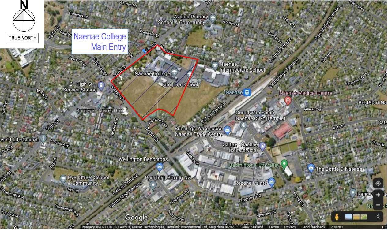
Project Name:
Naenae College
Administration Exterior
Project Address:
910 High Street
Avalon Hutt City
Prepared for:
Naenae College
Issued for:
WRP Review & Procurement
Location Plan
|
Scale 1:20000 |
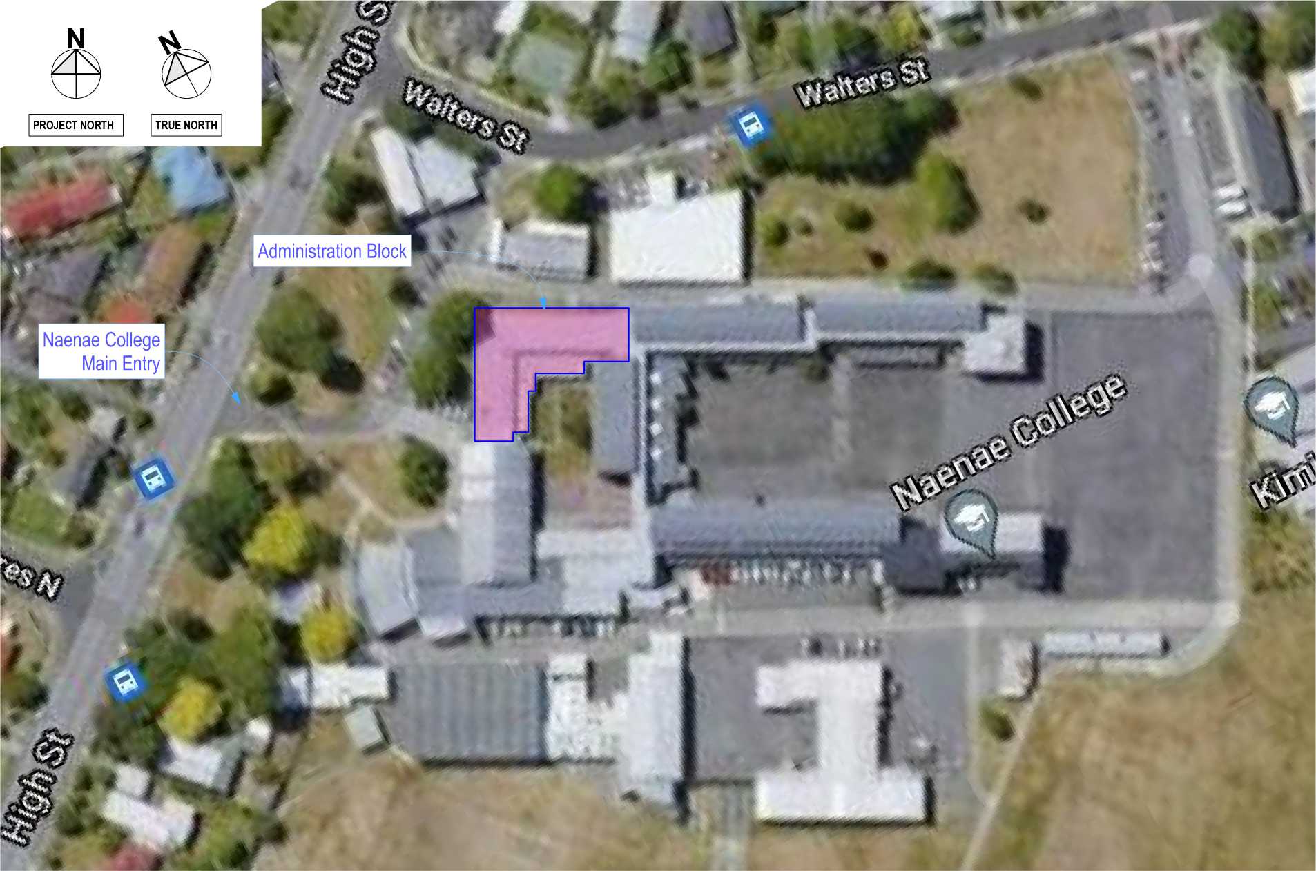 |
|
Revision | ||
|
500 |
Construction Details |
A |
|
501 |
Construction Details |
A |
|
502 |
Construction Details |
A |
|
503 |
Construction Details |
A |
|
504 |
Construction Details |
A |
|
505 |
Construction Details |
A |
|
506 |
Construction Details |
A |
|
507 |
Construction Details |
A |
|
508 |
Construction Details |
A |
|
509 |
Construction Details |
A |
|
510 |
Construction Details |
A |
|
511 |
Construction Details |
A |
|
512 |
Construction Details |
A |
|
513 |
Construction Details |
A |
|
514 |
Construction Details |
A |
|
515 |
Construction Details |
A |
|
516 |
Construction Details |
A |
|
517 |
Construction Details |
A |
|
700 |
Joinery Schedule |
A |
Architectural Drawings
|
No. |
Sheet Name |
Revision |
|
000 |
Location Plan |
A |
|
001 |
General Notes |
A |
|
100 |
Plan - Ground - Existing/Demo |
A |
|
101 |
Plan - Clerestory - Existing/Demo |
A |
|
102 |
Plan - Roof - Existing/Demo |
A |
|
110 |
Plan - Ground - Proposed |
A |
|
111 |
Plan - Ground - Proposed 1:50 |
A |
|
112 |
Plan - Clerestory - Proposed |
A |
|
113 |
Plan - Roof - Proposed |
A |
|
114 |
Plan - Rainfall Calculation |
A |
|
200 |
Elevations - Existing |
A |
|
201 |
Elevations - Existing |
A |
|
210 |
Elevations - Proposed |
A |
|
211 |
Elevations - Proposed |
A |
|
212 |
3D Views - Proposed |
A |
|
213 |
3D Views - Existing & Proposed |
A |
|
214 |
3D Views - Existing & Proposed |
A |
|
300 |
Sections |
A |
|
301 |
Sections |
A |
|
302 |
Sections |
A |
|
303 |
Sections - Proposed Enlarged 1:20 |
A |
|
304 |
Sections - Proposed Enlarged 1:20 |
A |
PROPERTY INFORMATION
Parcel ID:
Legal Description:
Address:
Earthquake Zone:
Exposure Zone:
Climate Zone:
Wind Region:
Lee Zone:
Rainfall Intensity:
Wind Zone :
3944421 & 4053628 Lots 1 & 2 DP 18397 910 High Street, Avalon.
Zone 3
Zone C
Zone 2
W
No
70
Very High
Project No:R21112
Date:Monday, 15 August 2022
Drawing :Location Plan, DWG 000 Rev -A
RESOLVE’:
ARCHITECTS
PO BOX 9792, WELLINGTON - RESOLVEiTARCHITECTS.CO.NZ
|
EXISTING AND DEMO PLAN 2110 Demolition I I Existing timber framed walls to remain. Remove elements indicated with hatching or broken lines an/or notation as required to facilitate roof and exterior wall remediation. Remove existing interior walls, linings etc as per interiors package by IR Group. Walls & Windows: rW rWX rRWX Remove existing direct fixed timber boards or fibre cement sheet wall claddings and underlay. Window to be removed. Refer to Existing/Demo Plan & Elevations. Window to be removed and retained for re-use into existing opening. Remediate and store securely. Refer to Existing/Demo Plan & Elevations. Roofs and Skylights: eR rR rSX rCX Existing roof retained, prepare for new overlay roof system. Existing profiled metal roof cladding and underlay removed. Existing skylight to be removed. Existing canopy to be removed. Spouting and Downpipes: Remove all spouting and downpipes. Allow to temporarily remove all pipes, vent grates, antenas, lights, taps, misc items as required for removal of wall cladding and set aside for reinstallation or replace with new if required after reclad. 3897 Replacement & Treatment of Decayed Timber Replacing Covered Rotten Timber The following is an outline summary of the what to do if rotten timber or timber with excess moisture content is found where cladding is removed to carry out remedial work. Excess moisture in timber is defined as timber with a moisture content in excess of 16%.
Photographic record of existing timber framing to be made.
Refer to specification section 3897 Replacement & Treatment of Decayed Timber Refer also to Quality Assurance Plan |
PROPOSED PLAN GENERAL NOTES
3820 Carpentry wall framing notes: NOTE: All timber framing to be SG8 unless noted otherwise Windzone is Very High for all NZS3604:2011 tables and figures. All existing timber framed walls remain. Remediate/replace damaged timbers as per directive of qualified timber remediation specialist. For all timber treatments refer to carpentry section of the specification. Allow for solid blocking to wall framing to support apron upstand and cavity construction. Allow for solid blocking to wall framing to support shelving, lining edges... etc. Allow for doubling stud under ends of all lintels, allow for trimming studs as per NZS3604:2011 table 8.5, or refer to engineer's dwgs. Allow for double studs to all vertical sheet joins to new Hardiflex exterior cladding. Lintel fixing to trimmer studs refer to NZS 3604: 2011 Table
Fixing trimmer studs to floor. (Refer NZS 3604: 2011 figure
Refer bracing specification and plans for specific requirements for bracing walls. Fixing roof framing to wall framing refer to NZS 3604:2011 table 10.1. NOTE: refer to engineers drawings for:
Timber trim - Exterior: Refer to details. Timber trim - Interior: Refer to IR Group interior project documentation. Wall Cladding: Refer to elevations for exterior wall claddings. Windows and Skylights: nWX New window joinery: Refer 4521AE for APL ALUMINIUM WINDOWS & DOORS - EDUCATION FACILITIES nSX New Skylight: Refer 4554VS for VELUX OPENING & FIXED SKYLIGHTS 4711P PINK® BATTS® & BIB INSULATION
Typical Insulation Notes:
5120 Linings Wall lining notes: Refer to IR Group interior project documentation. Exterior Fittings: Allow to reinstate all pipes, vent grates, antennas, lights, taps, misc items as required which were removed to carry out the remedial work. |
ROOF PLAN 4300 GENERAL ROOFING NOTES Exposure Zone: C Wind Zone: Zone VH Refer to Relevant Trade Specification Sections Refer to manufacturers installation instructions & BRANZ appraisals. Refer to CONSTRUCTION DETAILS 500 series drawings. NOTE: all roof penetrations/flashings are to be within the scope of work of the roofing contractor eR nR1 nR2 Existing roof cladding retained. New overlay roof system with waterproof membrane roof cladding. New overlay roof system with waterproof membrane on plywood substrate over new entrance roof structure. ROOF FRAMING 3820 Carpentry (roof framing notes):
Truss design, refer specification for truss design & layout. new proprietary roof truss, H1.2 treated at 900mm max ctrs as shown. ROOF CLADDING 4161T THERMAKRAFT UNDERLAYS, FOILS, DPC, DPM, & TAPES For underlays that are not part of the Roof Logic Ultrtherm MSR & Xtreme systems. Roof Underlay: Thermakraft Covertek 407 Flashing Tape: Thermakraft ThermaFlash. Joining Tape: Thermakraft general purpose tape. Existing steel roof cladding: trapezoidal and tray profile roof on existing roof structure to remain in place to avoid disturbing asbestos layer beneath. New overlay roof system installed over exisitng metal roof cladding. Roof Fixing: Roof Fixings by overlay roof system manufacturer to be approporiate for the design loads of site. Allow for specific loadings @ corners & the periphery of the roof where localised pressure factors apply Roof fixing in Very High Wind Zones (refer 3604 for specific fixing types) 4337E ECOPLY ROOFING & DECKING Substrate:19mm H3.2 CCA treated CD plywood fix with s/s screws, butt jointed allow 3mm gap between sheets with tape over. 4424RL ROOFLOGIC ULTRATHERM XTREME FIBERTITE ROOFING SYSTEM Membrane: RL single ply membrane, Colour: Slate Grey PIR insulation: RL PIR board 40mm . Vapour Barrier: RL Vapour barrier. Basedeck: New plywood substrate. 4821 Roof Flashings To be fabricated from same material as roof unless detailed otherwise. Material: Colorsteel Maxx BMT 0.55 Min. Saddle Flashings: Aluminium fully welded BMT 1.6 Min. Powdercoated. 4550 Roof Windows and Skylights
https://www.velux.co.nz/products/skylights Provide additional framing to edge of roofing penetration and to create curb upstand as per detail and per NZBC E2/AS1 fig. 21. Cricket Diverter: Create a cricket diverter from PIR. 7411 Rainwater Spouting System
NOTE: New section of SW drain shown on ground level plan Downpipe positions as per Plans and Elevations. ROOF CATCHMENT PLAN Catchment Calculations - (NZBC Clause E1: Table 5) Rainfall Intensity (range): 60-70mm/hr (BRANZ Maps) Spoutings and Downpipes: Refer to Rainwater Calculation Plan. |
ELEVATIONS Wall cladding scope: Clerestory and dormer walls only. Ground level wall cladding to remain (To be remediated at a later stage). Wall Cladding - note key to match model elevation Various existing direct fixed wall claddings: Timber vertical shiplap Fibre Cement.
New vertical fibre cement panels over a drained and ventilated cavity. James Hardie Axon Panel 133 Smooth Paint finished, Colour: 6711R Resene Painting Exterior. New fibre cement panels over a drained and ventilated cavity. James Hardie EasyLap Panel Paint finished. Colour: 6711R Resene Painting Exterior. nR1 nR2 nSX New overlay roof system with waterproof membrane cladding installed over existing metal roof cladding. New overlay roof system with waterproof membrane cladding installed over new plywood substrate. New skylight. 4221KH KLC HORIZONTAL WEATHERBOARD CLADDING SYSTEM Fascias: Ex 230x18 and 280x18, H3.2, Paint Finish. Barges: Ex 230x18 and 280x18, H3.2, Paint Finish. Cavity Battens: 45x20 H3.2 Cavity Closers: WANZ rigid PVC cavity closer, 9010500 OR : WANZ Aluminium Cavity Closer Fixings - Nail, Screw Fastenings
4161 Wraps, Underlay and DPC
Seal all around opening to cladding with flexible sealant. 4171 Rigid Air Barrier James Hardie Rigid Air Barrier System:
WINDOWS & DOORS All windows to comply with NZS 4211 4521 Aluminium Windows & Doors 
Window to be removed. Refer to Existing/Demo plan. New window. Refer to Proposed plan. APL Architectural Series 158mm APL Shop Front APL Architectural Series 106mm APL Mero Series (All new windows).
Finish Powder Coat: Dulux Duratech, Thickness: 60 microns minimum Colour: to be confirmed Reveals
Window Hardware
|
Installation
windows & doors only.
NOTE: DO NOT USE EXPANDING FOAM TO GAP BETWEEN REVEALS AND WALL OPENING NOTE: DO NOT USE SILICON SEALANT IN COMBINATION WITH BITUMEN BASED FLASHING PRODUCTS 4610 Glazing Exterior All glazing Double glazed. Double glazing to be Low E coated (surface 2) and Argon filled. Inner pane to be laminated.
- Penetrations: Marshall TradeSeal one piece self adhesive collar to RAB board. Size to suit pentration. Seal all around opening to cladding with flexible sealant. 5230 Interior Doors
6700R Resene Painting General
6721R Resene Painting Interior
6711R Resene Painting Exterior Refer specification for paint systems to be used. Scope:
Colours: RESOLVE'; ARCHITECTS
LEVEL 1, 171 VIVIAN STREET, TE ARO PO BOX 9792, WELLINGTON RESOLVEiTARCHITECTS.CO.NZ CAD File: S:\Projects\R21112 - Naenae College Roof Remediation\A-Cad\R21112 Naenae College Admin Block-Developed Design 220727.pln Client: Naenae College Project Name: Project Number: R21112 Naenae College Administration Exterior Project Address: 910 High Street Avalon Hutt City
| |||||||||||||||||||||||||||||||||||||||||||||||||||||||||||||||||||||||||||||||||||||||||||||||||||||||||||||||||||||||||||||||||||||||||||||||||
|
33,648 N PROJECT NORTH co Existing windows and wall claddings. Remove existing porch, stairs and external door. Remove exterior cladding back to the line of the projecting concrete wall. | |
|
Remove window. New and existing wall cladding demarcation point. | 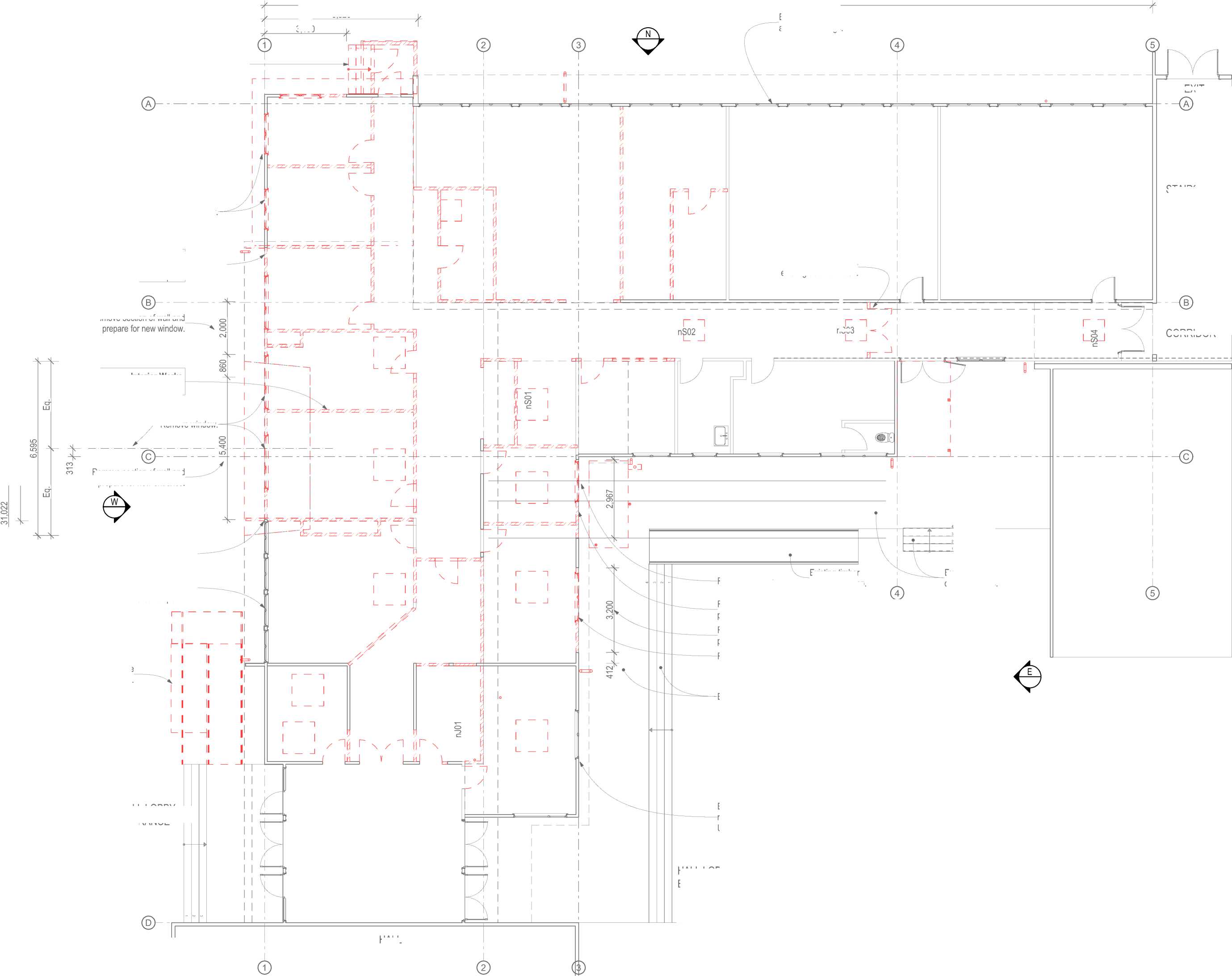
EXIT Remove section of wall and nS03 CORRIDOR HALL 4 3 2 1 5,820 3,100 |
|
Remove window. .Existing timber deck and stairs. D 5m Existing timber .deck and stairs. Existing windows and wall cladding retained and refurbished as required. Unless noted otherwise. Remove existing ramp. Remove section of wall and prepare for new window. Remove section of wall and prepare for new door. Remove window. 10m 1:100 - A2 0 1m 2m L | |

|
Remove existing windows and wall claddings north of wall cladding demarcation point. |
--— |
Interior Works
Refer to IR Group documentation.
Centre line of proposed new entrance.
Remove window.
Remove section of wall and prepare for new entrance.
Make good existing wall cladding and windows south of wall cladding demarcation point.
HALL LOBBY ENTRANCE
HALL LOBBY ENTRANCE
STAIRS
Remove and retain existing door for reuse.
Existing timber accessible ramp.

The contractor shall confirm all conditions and dimensions on site before proceeding with work. Do not scale dimensions off drawings. Contractor is to report any discrepancies to the architect immediately. Plans to be read in conjunction with the specification. RIA accepts no responsibility for any changes made to the issued documents.
| |||||||||||||||||||||||||||||||||||||||||||||
|
Copyright RESOLVEiTARCHITECTS 2022© |
EXISTING AND DEMO PLAN KEY NOTES: REFER SHEET 001
RESOLVE';
ARCHITECTS
LEVEL 1, 171 VIVIAN STREET, TE ARO
PO BOX 9792, WELLINGTON
RESOLVEiTARCHITECTS.CO.NZ
Client:
Naenae College
Project Name:
Project Number: R21112
Naenae College
Administration Exterior
Project Address:
910 High Street Avalon Hutt City
Drawing Title:
Plan - Ground -Existing/Demo
Status: WRP Review & ProcurDate:t 15/08/2022
Scale: 1:100
Drawing No.
100
Size: A2
Revision No.
A
CAD File: S:\Projects\R21112 - Naenae College Roof Remediation\A-Cad\R21112 Naenae College Admin Block-Developed Design 220727.pln
N

PROJECT NORTH
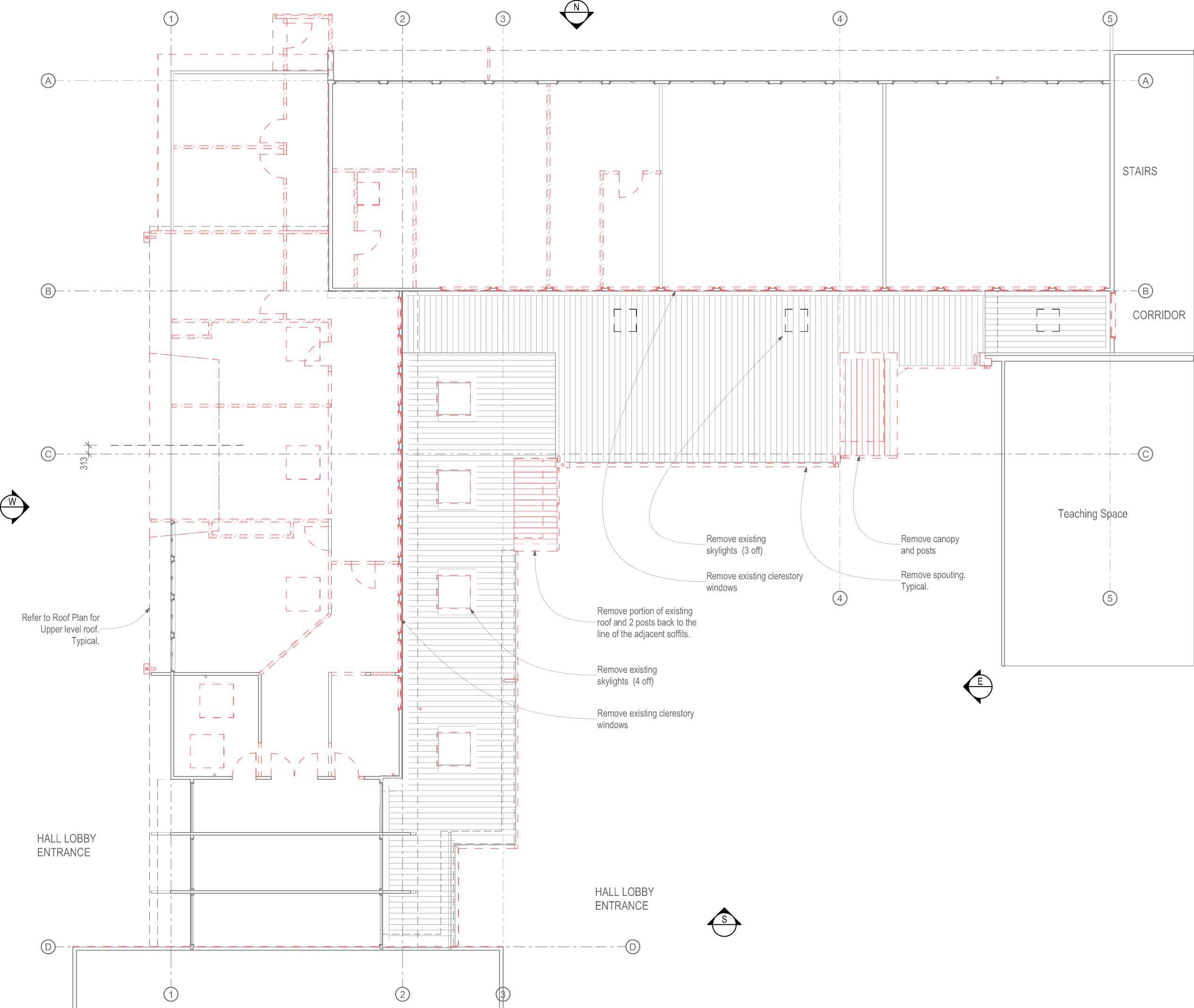
The contractor shall confirm all conditions and dimensions on site before proceeding with work. Do not scale dimensions off drawings. Contractor is to report any discrepancies to the architect immediately. Plans to be read in conjunction with the specification. RIA accepts no responsibility for any changes made to the issued documents.
| |||||||||||||||||||||||||||||||||||||||||||||
|
Copyright RESOLVEiTARCHITECTS 2022© |
EXISTING AND DEMO PLAN KEY NOTES: REFER SHEET 001
RESOLVE';
ARCHITECTS
LEVEL 1, 171 VIVIAN STREET, TE ARO PO BOX 9792, WELLINGTON
RESOLVEiTARCHITECTS.CO.NZ
Client:
Naenae College
Project Name: Project Number: R21112
Naenae College
Administration Exterior
Project Address:
910 High Street Avalon Hutt City
Drawing Title:
Plan - Clerestory -Existing/Demo
Status: WRP Review & ProcurDate:t 15/08/2022
0 1m 2m 5m 10m
] 1:100 - A2
|
Scale: 1:100 Size: A2 | ||||
|
CAD File: S:\Projects\R21112 - Naenae College Roof Remediation\A-Cad\R21112 Naenae College Admin Block-Developed Design 220727.pln
N

|
33,648 28,060 | |
|
PROJECT NORTH | 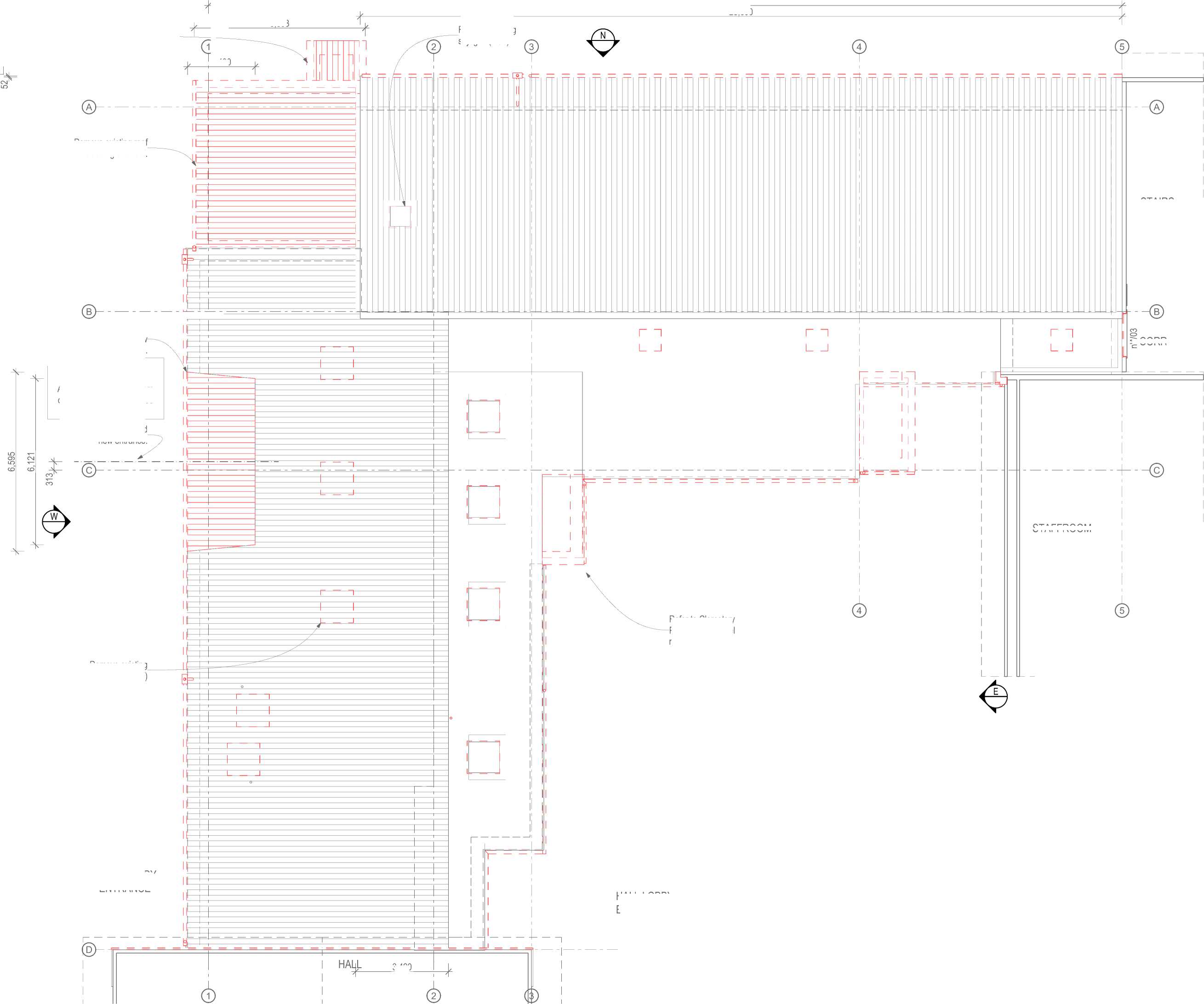
6,303 STAFFROOM 3,420 |
|
D | |
Remove existing porch roof cladding and roof.
Remove existing roof cladding and roof.
Remove existing roof cladding and roof for new Administration Entrance.
NOTE
Roof works fo the new Administration Entrance are dependant on the proposed ground level floor plan.
Centre line of proposed new entrance.
Remove existing skylights (5 off)
HALL LOBBY ENTRANCE
Scale 1:100
2,490
Remove existing skylight (1 off)
The contractor shall confirm all conditions and dimensions on site before proceeding with work. Do not scale dimensions off drawings. Contractor is to report any discrepancies to the architect immediately. Plans to be read in conjunction with the specification. RIA accepts no responsibility for any changes made to the issued documents.
STAIRS
CORRIDOR
Refer to Clerestory Plan for lower level roof. Typical.
HALL LOBBY ENTRANCE

| |||||||||||||||||||||||||||||||||||||||||||||
|
Copyright RESOLVEiTARCHITECTS 2022© |
EXISTING AND DEMO PLAN KEY NOTES: REFER SHEET 001
RESOLVE1;
ARCHITECTS
LEVEL 1, 171 VIVIAN STREET, TE ARO
PO BOX 9792, WELLINGTON
RESOLVEiTARCHITECTS.CO.NZ
Client:
Naenae College
Project Name:
Project Number: R21112
Naenae College
Administration Exterior
Project Address:
910 High Street Avalon Hutt City
Drawing Title:
Plan - Roof -
Existing/Demo
Status: WRP Review & ProcurDate:t 15/08/2022
|
Scale: 1:100 Size: A2 | ||||||||||||
|
CAD File: S:\Projects\R21112 - Naenae College Roof Remediation\A-Cad\R21112 Naenae College Admin Block-Developed Design 220727.pln
|
33,648 N 3,600 5,820 PROJECT NORTH co Zig-Zag line defines extent of new wall cladding scope. Existing windows and wall claddings. New and existing wall claddings demarcation point. Timber palisade barrier. New wall structure on new foundation |
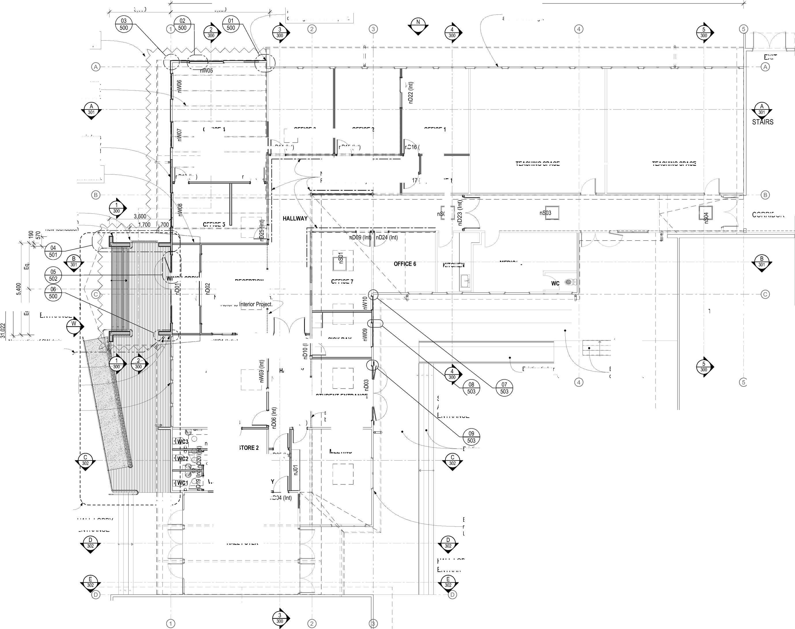
EXIT nD15 (Int) nD1 TEACHING SPACE TEACHING SPACE CORRIDOR OFFICE 5 KITCHEN IND LOBBY OFFICE 7 4 MEETING nD05 (In nD0 nD (Int) OFFICE 4 nD13 (Int) |
|
.Existing timber deck and stairs. HALL 2m 5m Existing timber .deck and stairs. Existing windows and wall claddings, make good as required. Existing windows and wall cladding retained and refurbished as required. Unless noted otherwise. New and existing wall claddings demarcation point. 10m 1:100 - A2 0 1m New Stairs, Decking and Accessible Ramp. Refer to enlarged 1:50 Plan 4 3 2 1 |

New timber trusses above. Setout and design by Str. Eng or truss manufacturer.
New exterior doors, windows and wall claddings to the new Administration Entrance and walls north of demarcation point.
Interior Works
Refer to IR Group documentation.
ADMINISTRATION ENTRANCE
New section of SW drain connecting to existing SW main (Indicative). /'
New downpipe connecting to a new section of stormwater drain.
HALL LOBBY ENTRANCE
4
nD12 (Int)
RECEPTION
New non-structural screen Refer to
nW01 (Int)nW02 (Int)
ADMIN
|
nD08 | |
|
1 (In |  |
Ceiling Hatc 560 /560
WC LO
HALL FOYER
OFFICE 3
OFFICE 2
OFFICE 1
(Int)
nD07 (Int) ^
ALLWAY
nD11 (Int)
WAIT
New glazed aluminium partitions .Refer to Interiors Project.
SICK BAY
STUDENT ENTRANCE
New non-structural screen, design to be confirmed.
nD1
(Int) STORE 1
MEDICAL
Existing timber accessible ramp.
TEACHING SPACE
STUDENT
ADMINISTRATION
ENTRANCE

HALL LOBBY ENTRANCE

The contractor shall confirm all conditions and dimensions on site before proceeding with work. Do not scale dimensions off drawings. Contractor is to report any discrepancies to the architect immediately. Plans to be read in conjunction with the specification. RIA accepts no responsibility for any changes made to the issued documents.
| |||||||||||||||||||||||||||||||||||||||||||||
|
Copyright RESOLVEiTARCHITECTS 2022© |
PROPOSED PLAN KEY NOTES: REFER SHEET 001
RESOLVE';
ARCHITECTS
LEVEL 1, 171 VIVIAN STREET, TE ARO
PO BOX 9792, WELLINGTON
RESOLVEiTARCHITECTS.CO.NZ
Client:
Naenae College
Project Name:
Project Number: R21112
Naenae College
Administration Exterior
Project Address:
910 High Street Avalon Hutt City
Drawing Title:
Plan - Ground - Proposed
Status: WRP Review & ProcurDate:t 15/08/2022
Scale: 1:100
Drawing No.
110
Size: A2
Revision No.
A
CAD File: S:\Projects\R21112 - Naenae College Roof Remediation\A-Cad\R21112 Naenae College Admin Block-Developed Design 220727.pln
N

PROJECT NORTH
Top of Stair handrail height 900-1,000
Deck Specification
Design load: 3kPa as per MOE requirements.
(NZS 3604 3kPa Floor Loading)
Decking: 88 x32 H3.2
Joist: 140x45 Min. SG8 H3.2, (Span 2.15m Max).
Bearer: 90x90 SG8 H3.2, Span 1,300 Max. Loaded dimension 1,000 Max.
Pile: 125x125 H5
Footing Concrete: 225x225x200 Min
Stringers 140x45 Min. H3.2 Bolts M12 at 0.7m centres Max.
Concrete plinth to support timber stairs shown hidden.
New Main Entry Stairs
Final bottom of stair relative height to be determined by the new ground level of the new landscape plan.
Stair dimensions to NZS 4121
Riser: 160 Min. -180 Max.
Going: 310 Min - 350 Max.
Constrasting nosings to stair treads and landing.
Final bottom of ramp relative height and position to be determined by the new ground level of the new landscape plan.
Pile setout is indicative and requires confirmation on site, pile spacing 2,000 centres (2,150 Max.).
Pile setout is indicative and requires confirmation on site, pile spacing 1,300 Max. centres.
Concrete Accessible Ramp
Slope 1:12 Max.
Slip resistance, broom finish 0.4µ Min.
|
310 nW0 3,600 ___________L 2,555 _____ 1,700 | |
|
Top of Deck handrail height 900-1,000 Top of Ramp handrail height 840-900 | 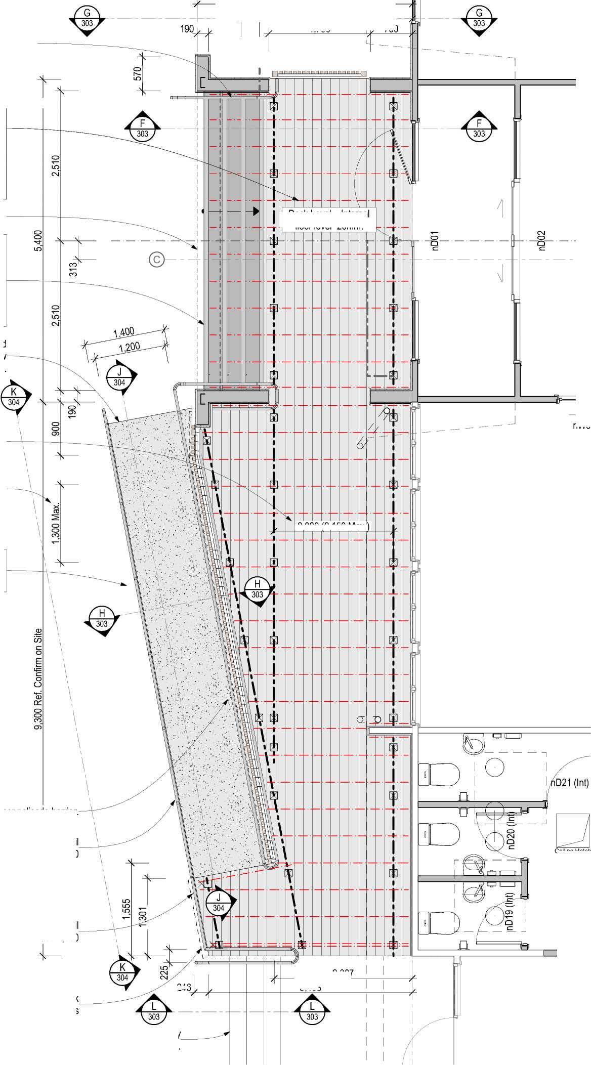
700 2 246 150 Max.) ,000 (2 |
|
Ceiling Hatch 560 /560 entry steps. | |
Timber palisade barrier.
Dress exposed sides of deck with vertical decking timbers
Deck Level = Internal floor level -20mm.
2,307
3,403
The contractor shall confirm all conditions and dimensions on site before proceeding with work. Do not scale dimensions off drawings. Contractor is to report any discrepancies to the architect immediately. Plans to be read in conjunction with the specification. RIA accepts no responsibility for any changes made to the issued documents.
| |||||||||||||||||||||||||||||||||||||||||||||
|
Copyright RESOLVEiTARCHITECTS 2022© |
PROPOSED PLAN KEY NOTES: REFER SHEET 001
RESOLVE1;
ARCHITECTS
LEVEL 1, 171 VIVIAN STREET, TE ARO
PO BOX 9792, WELLINGTON
RESOLVEiTARCHITECTS.CO.NZ
Client:
Naenae College
Project Name: Project Number: R21112
Naenae College
Administration Exterior
Project Address:
910 High Street Avalon Hutt City
|
Status: WRP Review & ProcurDate:t 15/08/2022 Scale: 1:50, 1:100 Size: A2 | ||||||||||||
|
CAD File: S:\Projects\R21112 - Naenae College Roof Remediation\A-Cad\R21112 Naenae College Admin Block-Developed Design 220727.pln
|
N |
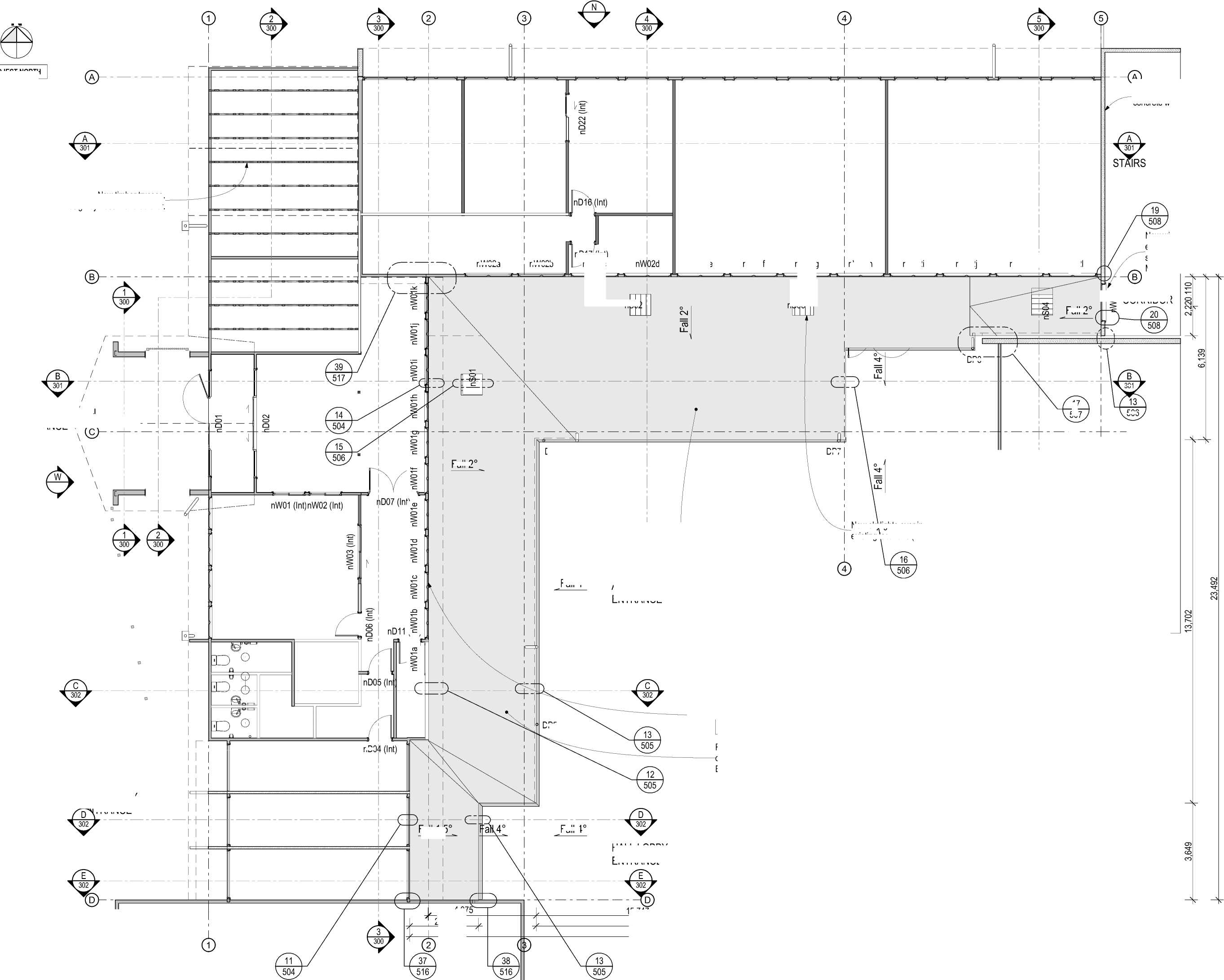
nW02a nW02b Fall 2 DP8 DP7 Fall 2 DP5 nD0 Fall 1.5 Fall 4 Fall 4° 17 18 B |
|
PROJECT NORTH C 5 15,747 11,685 5m New clerestory windows within existing openings. Sills raised to provide 150 upstand to new roof cladding. Typical 17,373 26,060 Remediate existing roof with new membrane & PIR overlay roofing over existing metal tray roof. Existing roof pitch varies 1° - 2°, New pitch 2° nominal. Remediate existing roof with new membrane & PIR overlay roofing over existing metal tray roof. Existing roof pitch varies 1° - 2°, New pitch 2° nominal. Teaching Space 4,07 2,590 0 1m 2m L |
New timber trusses.
Design by truss manufacturer.
ADMINISTRATION
ENTRANCE e^--^-
HALL LOBBY TRANCE
DP6
nD17 (Int) nW02c
nW02e
nW02f
nW02g
nW02h
nW02i
nW02j
nW02 nW02l
nS02
nS03
Existing concrete wall.
New window fitted into existing opening. Opening size reduced. Upstand 150 Min. to new roof cladding.
<2 CORRIDOR
STUDE
ADMINISTRATION ENTRANCE

New skylights over in existing locations (4 off).

HALL LOBBY ENTRANCE


10m
1:100 - A2
The contractor shall confirm all conditions and dimensions on site before proceeding with work. Do not scale dimensions off drawings. Contractor is to report any discrepancies to the architect immediately. Plans to be read in conjunction with the specification. RIA accepts no responsibility for any changes made to the issued documents.
| |||||||||||||||||||||||||||||||||||||||||||||
|
Copyright RESOLVEiTARCHITECTS 2022© |
PROPOSED PLAN KEY NOTES: REFER SHEET 001
2ESOLVE
ARCHITECTS

LEVEL 1, 171 VIVIAN STREET, TE ARO
PO BOX 9792, WELLINGTON
RESOLVEiTARCHITECTS.CO.NZ
Client:
Naenae College
Project Name: Project Number: R21112
Naenae College
Administration Exterior
Project Address:
910 High Street Avalon Hutt City
|
Drawing Title: Plan - Clerestory - Proposed Status: WRP Review & ProcurDate:t 15/08/2022 Scale: 1:100 Size: A2 | ||||
|
CAD File: S:\Projects\R21112 - Naenae College Roof Remediation\A-Cad\R21112 Naenae College Admin Block-Developed Design 220727.pln
|
33,648 N New prefinished steel box gutter DP4 New gutter adjacent to existing concrete wall. Waterproof membrane on new plywood substrate. DP5 28,060 | ||
|
77H‘ I O oo New prefinished steel box gutter. New timber framed trusses. Design and spacing by truss manufacturer Hatched area represents new roof extension. Membrane on PIR over plywood substrate. Timber infill where skylights were removed (5 off). co co | 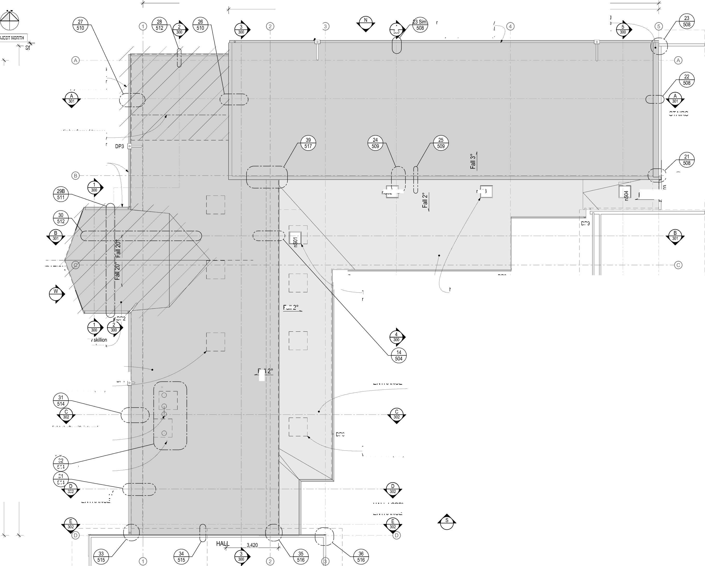
2 STAIRS nS03 DP9 Fall 2 nDP2 Fall DP6 4 300 32 31 D |
CORRIDOR Fall 2° New skylights over corridor at existing locations (3 off). Remediate existing metal tray roof cladding as required. Install new membrane & PIR overlay .roofing over existing roof cladding. Existing roof pitch varies 1° - 2°, New pitch 2° nominal. |
|
DP8 STAFFROOM 4 5 5m 1:100 - A2 0 1m 2m ru l | ||
PROJECT NORTH
ADMINISTRATION ENTRANCE
Hatched area represents new roof Pitch 20°. Clad with membrane on PIR over plywood substrate.
Remediate existing roof with new membrane & PIR overlay roofing over existing metal tray roof (Pitch 2° estimate).
New light shafts with integral mechanical extract over WC cubiles. Roof penetrations in locations where existing skylights were removed.
WC vent pipes (2 off)
HALL LOBBY ENTRANCE
DP1
nS02
DP7
|
New skylight at existing location. Timber infill existing opening as required to accept new skylight. |  |
STUDENT
ADMINISTRATION
ENTRANCE
Timber infill where skylights were removed (3 off).
HALL LOBBY ENTRANCE
Remediate existing roof with new membrane & PIR overlay roofing over existing metal tray roof (Pitch 3° estimate).

\ B


10m
The contractor shall confirm all conditions and dimensions on site before proceeding with work. Do not scale dimensions off drawings. Contractor is to report any discrepancies to the architect immediately. Plans to be read in conjunction with the specification. RIA accepts no responsibility for any changes made to the issued documents.
| |||||||||||||||||||||||||||||||||||||||||||||
|
Copyright RESOLVEiTARCHITECTS 2022© |
PROPOSED ROOF PLAN KEY NOTES: REFER SHEET 001
RESOLVE1:
ARCHITECTS
LEVEL 1, 171 VIVIAN STREET, TE ARO
PO BOX 9792, WELLINGTON
RESOLVEiTARCHITECTS.CO.NZ
Client:
Naenae College
Project Name: Project Number: R21112
Naenae College
Administration Exterior
Project Address:
910 High Street Avalon Hutt City
Drawing Title:
Plan - Roof - Proposed
|
Status: WRP Review & ProcurDate:t 15/08/2022 Scale: 1:100 Size: A2 | ||||
|
CAD File: S:\Projects\R21112 - Naenae College Roof Remediation\A-Cad\R21112 Naenae College Admin Block-Developed Design 220727.pln
N

The contractor shall confirm all conditions and dimensions on site before proceeding with work. Do not scale dimensions off drawings. Contractor is to report any discrepancies to the architect immediately. Plans to be read in conjunction with the specification. RIA accepts no responsibility for any changes made to the issued documents.
PROJECT NORTH
DP4
SP3
DP5
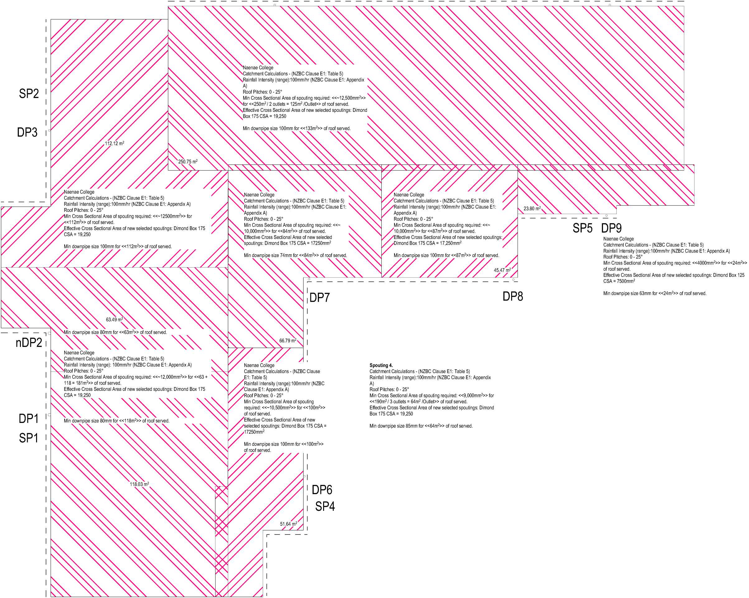
SP2 Min downpipe size 100mm for <<133m2>> of roof served DP3 Naenae College Catchment Calculations - (NZBC Clause E1: Table 5) Rainfall Intensity (range):100mm/hr (NZBC Clause E1: Appendix A) Min Cross Sectional Area of spouting required <<112m2>> of roof served SP5 DP9 Effective Cross Sectional Area of new selected spoutings: Dimond Box 175 Min downpipe size 63mm for <<24m2>> of roof served DP8 DP7 Min downpipe size 80mm for <<63m2>> of roof served nDP2 DP1 Min downpipe size 85mm for <<64m2>> of roof served SP1 DP6 SP4 Min Cross Sectional Area of spouting required: 10,000mm2>> for <<87m2>> of roof served. Min downpipe size 100mm for <<100m2>> of roof served. 112.12 m2 118.03 m2 66.79 m2 51.64 m2 23.80 m2 63.49 m2 CSA = 19,250 Effective Cross Sectional Area of new selected spoutings: Dimond Box 175 CSA = 17,250mm2 Naenae College Catchment Calculations - (NZBC Clause E1: Table 5) Rainfall Intensity (range):100mm/hr (NZBC Clause E1: Appendix A) Roof Pitches: 0 - 25° Min Cross Sectional Area of spouting required: <<~12,500mm2>> for <<250m2 / 2 outlets = 125m2 /Outlet>> of roof served. Effective Cross Sectional Area of new selected spoutings: Dimond Box 175 CSA = 19,250 Roof Pitches: 0 - 25° <<~ Naenae College Catchment Calculations - (NZBC Clause E1: Table 5) Rainfall Intensity (range):100mm/hr (NZBC Clause E1 Appendix A) Roof Pitches: 0 - 25° Min downpipe size 100mm for <<87m2>> of roof served. 45.47 m2 Min downpipe size 74mm for <<84m2>> of roof served. Naenae College Catchment Calculations - (NZBC Clause E1: Table 5) Rainfall Intensity (range):100mm/hr (NZBC Clause E1: Appendix A) Roof Pitches: 0 - 25° Min Cross Sectional Area of spouting required: <<~10,500mm2>> for <<100m2>> of roof served. Effective Cross Sectional Area of new selected spoutings: Dimond Box 175 CSA = 17250mm2 Spouting 4. Catchment Calculations - (NZBC Clause E1: Table 5) Rainfall Intensity (range):100mm/hr (NZBC Clause E1: Appendix A) Roof Pitches: 0 - 25° Min Cross Sectional Area of spouting required: <<9,000mm2>> for <<190m2 / 3 outlets = 64m2 /Outlet>> of roof served. Effective Cross Sectional Area of new selected spoutings: Dimond Box 175 CSA = 19,250 Naenae College Catchment Calculations - (NZBC Clause E1: Table 5) Rainfall Intensity (range): 100mm/hr (NZBC Clause E1: Appendix A) Roof Pitches: 0 - 25° Min Cross Sectional Area of spouting required: <<~12,000mm2>> for <<63 + 118 = 181m2>> of roof served. Effective Cross Sectional Area of new selected spoutings: Dimond Box 175 Naenae College Catchment Calculations - (NZBC Clause E1: Table 5) Rainfall Intensity (range):100mm/hr (NZBC Clause E1: Appendix A) Roof Pitches: 0 - 25° Min Cross Sectional Area of spouting required: <<4000mm2>> for <<24m2>> of roof served. Effective Cross Sectional Area of new selected spoutings: Dimond Box 125 CSA = 7500mm2 |
| |||||||||||||||||||||||||||||||||||||||||||||
|
Copyright RESOLVEiTARCHITECTS 2022© |
PROPOSED ROOF PLAN KEY NOTES: REFER SHEET 001
RESOLVE1;
ARCHITECTS
LEVEL 1, 171 VIVIAN STREET, TE ARO
PO BOX 9792, WELLINGTON
RESOLVEiTARCHITECTS.CO.NZ
Client:
Naenae College
Project Name: Project Number: R21112
Naenae College
Administration Exterior
Project Address:
910 High Street Avalon Hutt City
Drawing Title:
Plan - Rainfall Calculation
0 1m 2m 5m 10m
ii 1:100 - A2 i
|
Status: WRP Review & ProcurDate:t 15/08/2022 Scale: 1:100 Size: A2 | ||||
|
CAD File: S:\Projects\R21112 - Naenae College Roof Remediation\A-Cad\R21112 Naenae College Admin Block-Developed Design 220727.pln
Hall gable wall beyond.
Remove existing fibre cement wall cladding.
Assume to be asbestos unless proven otherwise.
15,500 Approximate.
Roof 1 +3,960 Clerestory +3,360
Ground Floor
+660
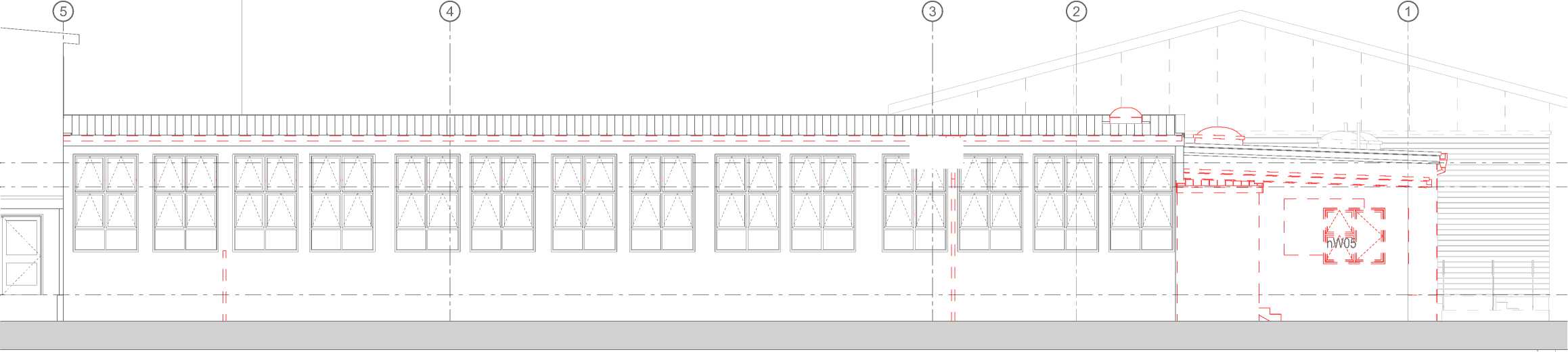
if |

North Elevation - Exist/Demo
Scale 1:100
Roof 1 +3,960 Clerestory +3,360
Ground Floor
+660
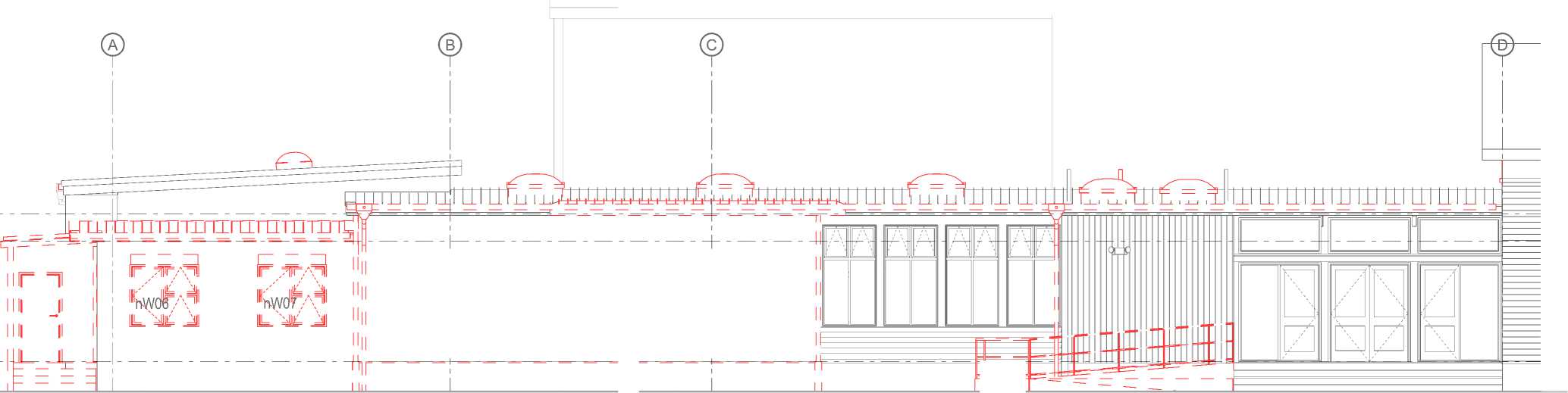
|
1 |
, OTTO —, | ||
|
r a M |
F 7T |
TA1 |
IF F T/FII |
|
\ Hr AT |
। \ Hr ATI1 | ||
|
lOfO |
M ^ nD01 |
11440 |

West Elevation - Exist/Demo
Scale 1:100
The contractor shall confirm all conditions and dimensions on site before proceeding with work. Do not scale dimensions off drawings. Contractor is to report any discrepancies to the architect immediately. Plans to be read in conjunction with the specification. RIA accepts no responsibility for any changes made to the issued documents.
| |||||||||||||||||||||||||||||||||||||||||||||
|
Copyright RESOLVEiTARCHITECTS 2022© |
EXISTING AND DEMO PLAN KEY NOTES: REFER SHEET 001
RESOLVE';
ARCHITECTS
LEVEL 1, 171 VIVIAN STREET, TE ARO PO BOX 9792, WELLINGTON
RESOLVEiTARCHITECTS.CO.NZ
Client:
Naenae College
Project Name: Project Number: R21112
Naenae College
Administration Exterior
Project Address:
910 High Street Avalon Hutt City
|
Status: WRP Review & ProcurDate:t 15/08/2022 Scale: 1:100 Size: A2 | ||||||||||||
|
CAD File: S:\Projects\R21112 - Naenae College Roof Remediation\A-Cad\R21112 Naenae College Admin Block-Developed Design 220727.pln
Roof 1
+3,960
Clerestory
+3,360
Ground Floor
+660


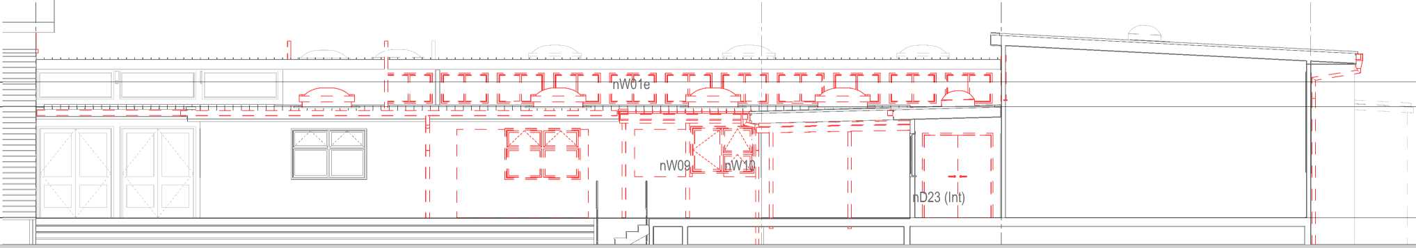
East Elevation - Exist/Demo
Scale 1:100
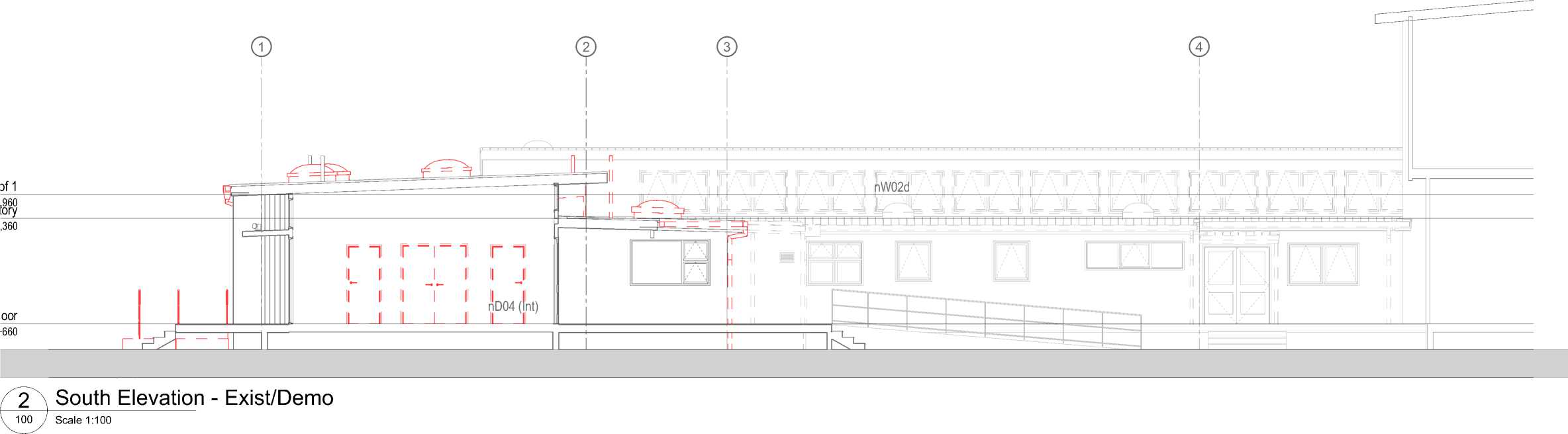
0 1m 2m
5m 10m
1:100 - A2
The contractor shall confirm all conditions and dimensions on site before proceeding with work. Do not scale dimensions off drawings. Contractor is to report any discrepancies to the architect immediately. Plans to be read in conjunction with the specification. RIA accepts no responsibility for any changes made to the issued documents.
| |||||||||||||||||||||||||||||||||||||||||||||
|
Copyright RESOLVEiTARCHITECTS 2022© |
EXISTING AND DEMO PLAN KEY NOTES: REFER SHEET 001
RESOLVE1;
ARCHITECTS
LEVEL 1, 171 VIVIAN STREET, TE ARO PO BOX 9792, WELLINGTON
RESOLVEiTARCHITECTS.CO.NZ
Client:
Naenae College
Project Name: Project Number: R21112
Naenae College
Administration Exterior
Project Address:
910 High Street Avalon Hutt City
|
Status: WRP Review & ProcurDate:t 15/08/2022 Scale: 1:100 Size: A2 | ||||
|
CAD File: S:\Projects\R21112 - Naenae College Roof Remediation\A-Cad\R21112 Naenae College Admin Block-Developed Design 220727.pln
Roof 1 +3,960 Clerestory +3,360
Ground Floor +660

The contractor shall confirm all conditions and dimensions on site before proceeding with work. Do not scale dimensions off drawings. Contractor is to report any discrepancies to the architect immediately. Plans to be read in conjunction with the specification. RIA accepts no responsibility for any changes made to the issued documents.
New fibre cement vertical shiplap wall cladding over drained cavity. Paint finish.
|
Existing timber and fibre cement wall cladding, paint finished. Refurbish as required. New spouting and downpipes. Hall gable wall beyond. New fibre cement sheet wall cladding over draind cavity to north facing gable. New timber batten balustrade. |
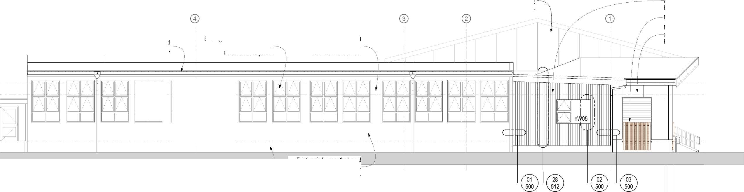 |
|
Existing timber weatherboard wall cladding, paint finished. Refurbish as required. Existing concrete foundation wall, paint finished. |
North Elevation - Proposed
Scale 1:100
Existing timber window joinery, paint finished. Refurbish as required.
New fibre cement sheet wall cladding over drained cavity. Paint finish.
| |||||||||||||||||||||||||||||||||||||||||||||
|
Copyright RESOLVEiTARCHITECTS 2022© |
ELEVATIONS KEY NOTES:
REFER SHEET 001
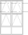
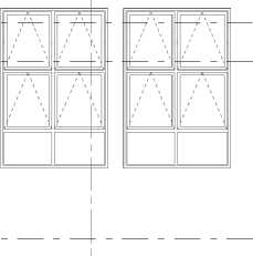
|
Terminal Vent (2 off). New light tubes c/w mechanical extract (3 off). New timber batten balustrade. | |
|
Roof 1 +3,960 Clerestory +3,360 | 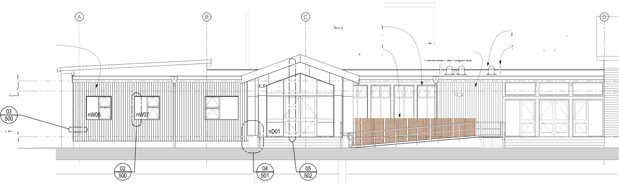 |
|
Ground Floor +660 | |
New fibre cement vertical shiplap wall cladding over drained cavity over synthethic breathable wall underlay and RAB.
Existing steel framed windows. Refurbish as required (4 off).
Existing timber paint finished wall cladding. Refurbish as required.
RESOLVE';
ARCHITECTS
LEVEL 1, 171 VIVIAN STREET, TE ARO PO BOX 9792, WELLINGTON
RESOLVEiTARCHITECTS.CO.NZ
Client:
Naenae College
Project Name: Project Number: R21112
Naenae College
Administration Exterior
Project Address:
910 High Street Avalon Hutt City
W West Elevation - Proposed
Scale 1:100
|
Status: WRP Review & ProcurDate:t 15/08/2022 Scale: 1:100 Size: A2 | ||||||||||||
|
CAD File: S:\Projects\R21112 - Naenae College Roof Remediation\A-Cad\R21112 Naenae College Admin Block-Developed Design 220727.pln

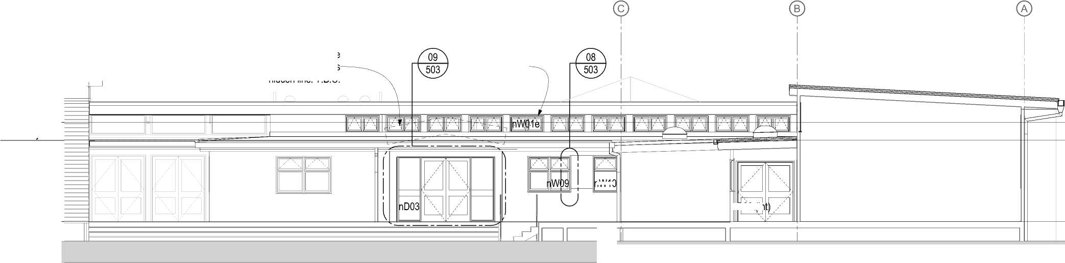
nW10 |
|
+3,360 |
New decorative facade treatment shown as hidden line. T.B.C.
New clerestory windows. Typical.
Roof 1 +3,960 Clerestory
Ground Floor
+660
D23 (In

East Elevation - Proposed
Scale 1:100
Roof 1 +3,960 Clerestory +3,360
Ground Floor
+660
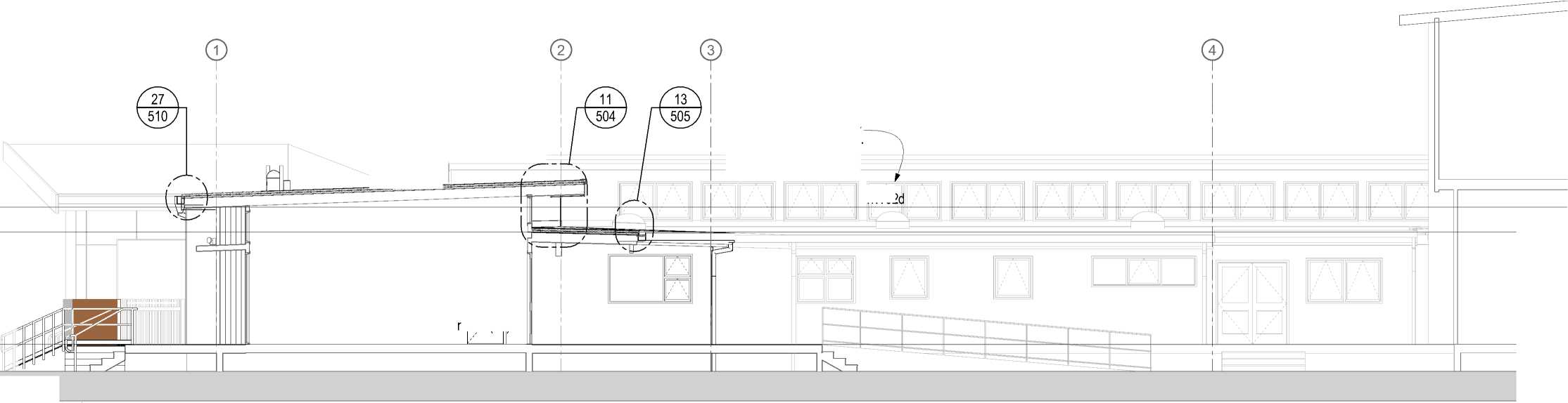
New clerestory windows. Typical.
nD04 (Int)
nW02

South Elevation - Proposed
Scale 1:100
The contractor shall confirm all conditions and dimensions on site before proceeding with work. Do not scale dimensions off drawings. Contractor is to report any discrepancies to the architect immediately. Plans to be read in conjunction with the specification. RIA accepts no responsibility for any changes made to the issued documents.
| |||||||||||||||||||||||||||||||||||||||||||||
|
Copyright RESOLVEiTARCHITECTS 2022© |
ELEVATIONS KEY NOTES:
REFER SHEET 001
RESOLVE';
ARCHITECTS
LEVEL 1, 171 VIVIAN STREET, TE ARO PO BOX 9792, WELLINGTON
RESOLVEiTARCHITECTS.CO.NZ
Client:
Naenae College
Project Name: Project Number: R21112
Naenae College
Administration Exterior
Project Address:
910 High Street Avalon Hutt City
|
Status: WRP Review & ProcurDate:t 15/08/2022 Scale: 1:100 Size: A2 | ||||||||||||
|
CAD File: S:\Projects\R21112 - Naenae College Roof Remediation\A-Cad\R21112 Naenae College Admin Block-Developed Design 220727.pln
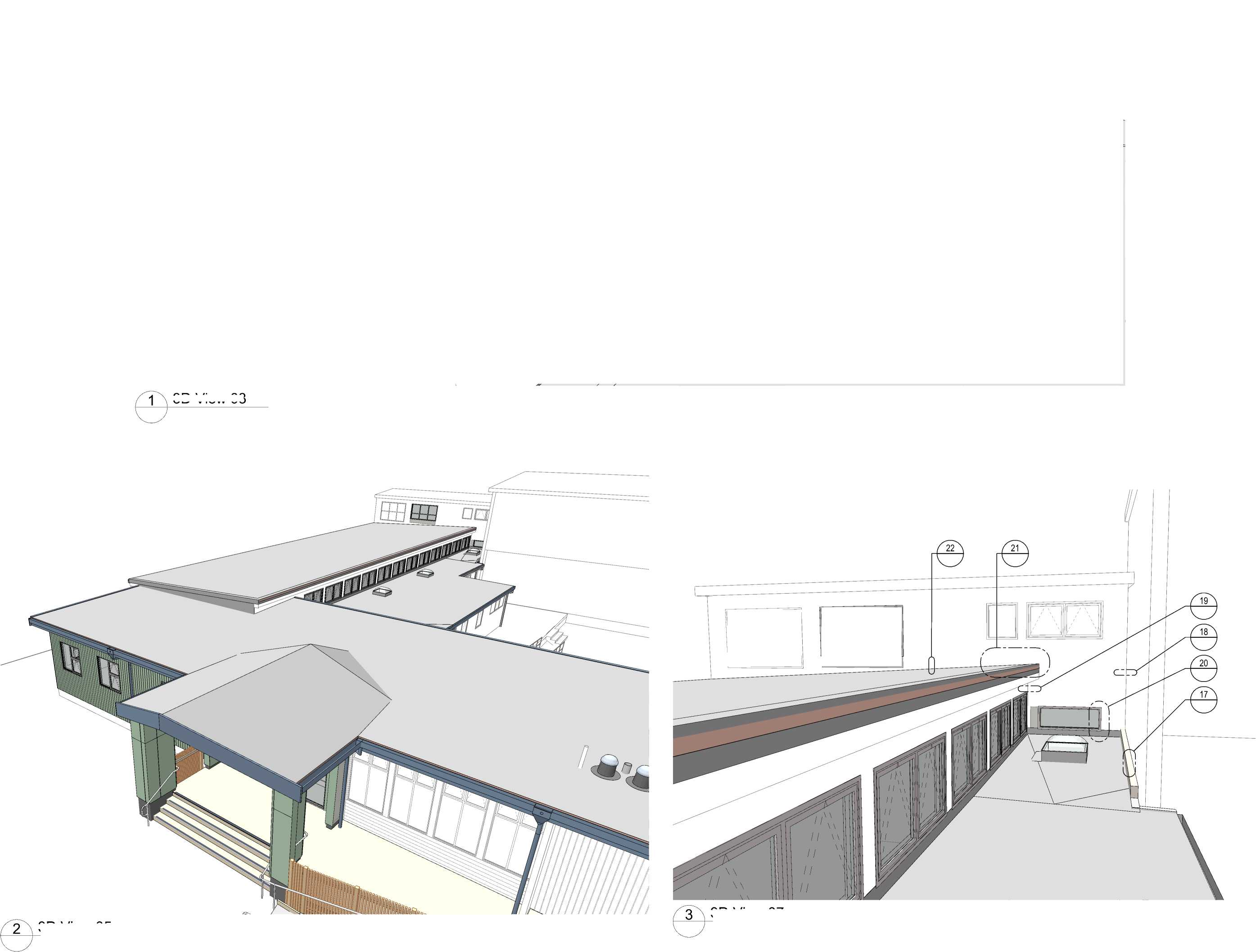
3D View 03 |
|
3D View 07 3D View 05 |
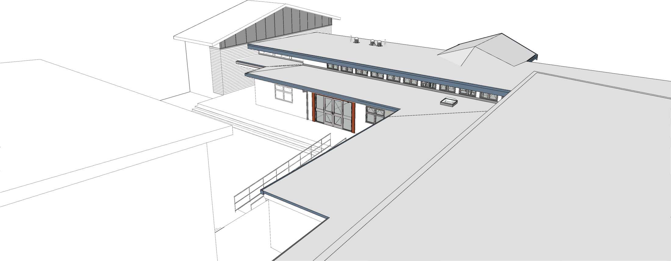
The contractor shall confirm all conditions and dimensions on site before proceeding with work. Do not scale dimensions off drawings. Contractor is to report any discrepancies to the architect immediately. Plans to be read in conjunction with the specification. RIA accepts no responsibility for any changes made to the issued documents.
| |||||||||||||||||||||||||||||||||||||||||||||
|
Copyright RESOLVEiTARCHITECTS 2022© |
RESOLVE';
ARCHITECTS
LEVEL 1, 171 VIVIAN STREET, TE ARO
PO BOX 9792, WELLINGTON
RESOLVEiTARCHITECTS.CO.NZ
Client:
Naenae College
Project Name:
Project Number: R21112
Naenae College
Administration Exterior
Project Address:
910 High Street Avalon Hutt City
Status: WRP Review & ProcurDate:t 15/08/2022
Scale:
Size:
Drawing No.
212
Revision No.
A
CAD File: S:\Projects\R21112 - Naenae College Roof Remediation\A-Cad\R21112 Naenae College Admin Block-Developed Design 220727.pln
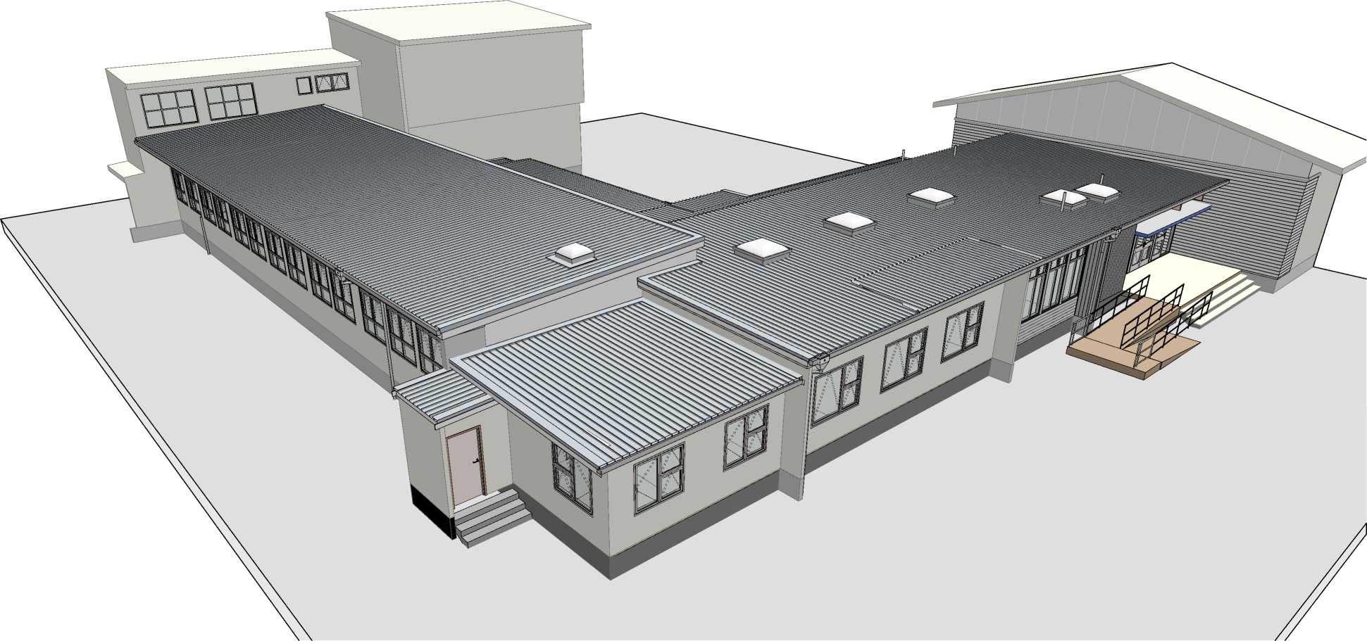

3D View 04 - Existing
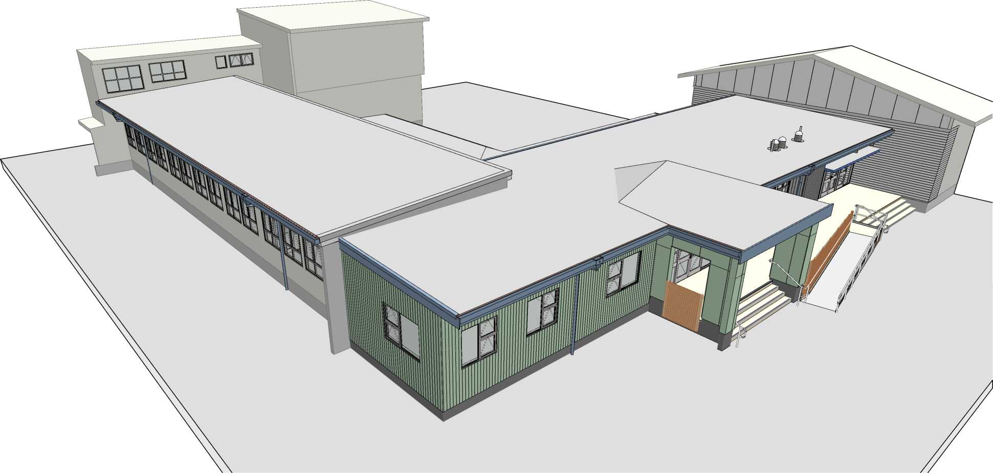
2 3D View 04 - Proposed
The contractor shall confirm all conditions and dimensions on site before proceeding with work. Do not scale dimensions off drawings. Contractor is to report any discrepancies to the architect immediately. Plans to be read in conjunction with the specification. RIA accepts no responsibility for any changes made to the issued documents.
| |||||||||||||||||||||||||||||||||||||||||||||
|
Copyright RESOLVEiTARCHITECTS 2022© |
RESOLVE';
ARCHITECTS
LEVEL 1, 171 VIVIAN STREET, TE ARO PO BOX 9792, WELLINGTON
RESOLVEiTARCHITECTS.CO.NZ
Client:
Naenae College
Project Name: Project Number: R21112
Naenae College
Administration Exterior
Project Address:
910 High Street Avalon Hutt City
Drawing Title:
3D Views - Existing &
Proposed
Status: WRP Review & ProcurDate:t 15/08/2022
Scale: Size:
|
Drawing No. |
Revision No. |
|
213 |
A |
CAD File: S:\Projects\R21112 - Naenae College Roof Remediation\A-Cad\R21112 Naenae College Admin Block-Developed Design 220727.pln
The contractor shall confirm all conditions and dimensions on site before proceeding with work. Do not scale dimensions off drawings. Contractor is to report any discrepancies to the architect immediately. Plans to be read in conjunction with the specification. RIA accepts no responsibility for any changes made to the issued documents.
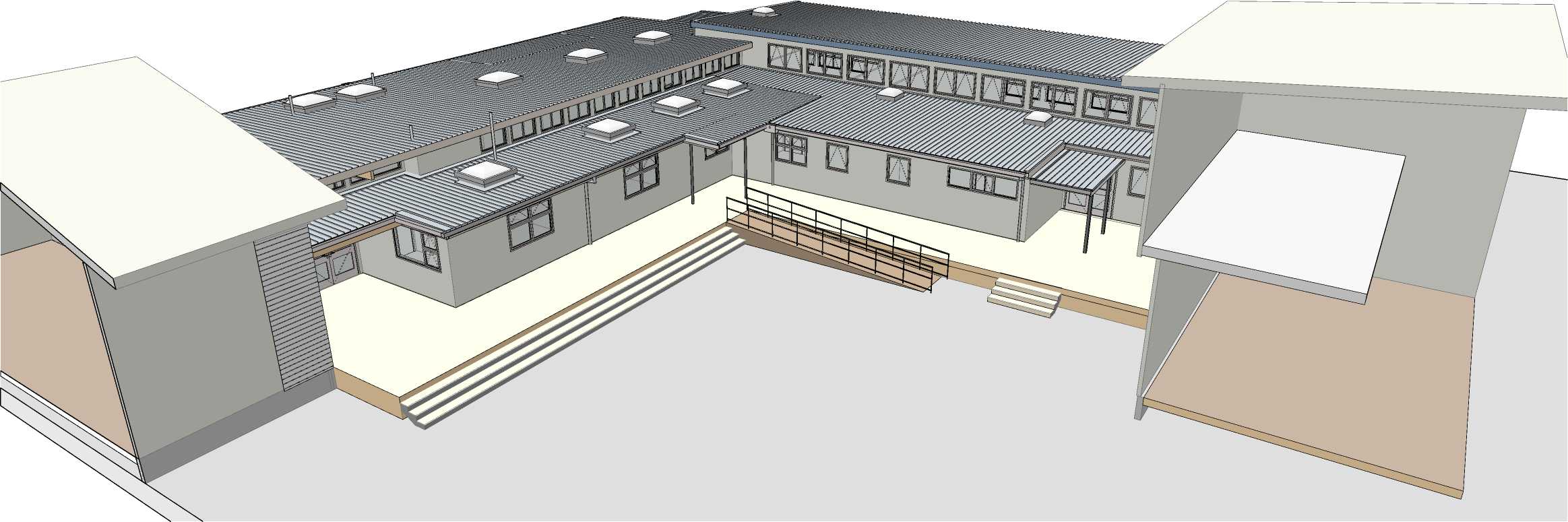
| |||||||||||||||||||||||||||||||||||||||||||||
|
Copyright RESOLVEiTARCHITECTS 2022© |

3D View 02 - Existing
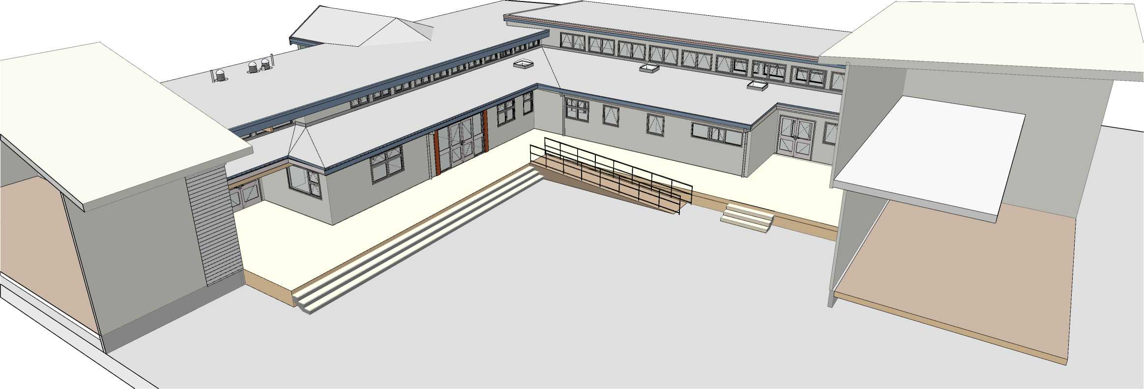
RESOLVE';
ARCHITECTS
LEVEL 1, 171 VIVIAN STREET, TE ARO PO BOX 9792, WELLINGTON
RESOLVEiTARCHITECTS.CO.NZ
Client:
Naenae College
Project Name: Project Number: R21112
Naenae College
Administration Exterior
Project Address:
910 High Street Avalon Hutt City

3D View 02 - Proposed
Drawing Title:
3D Views - Existing &
Proposed
Status: WRP Review & ProcurDate:t 15/08/2022
Scale: Size:
|
Drawing No. |
Revision No. |
|
214 |
A |
CAD File: S:\Projects\R21112 - Naenae College Roof Remediation\A-Cad\R21112 Naenae College Admin Block-Developed Design 220727.pln
2
|
Clerestory +660 Ground Floor Scale 1:100 Clerestory +660 Ground Floor Clerestory +660 Ground Floor Clerestory +660 Ground Floor 4 5 3 | 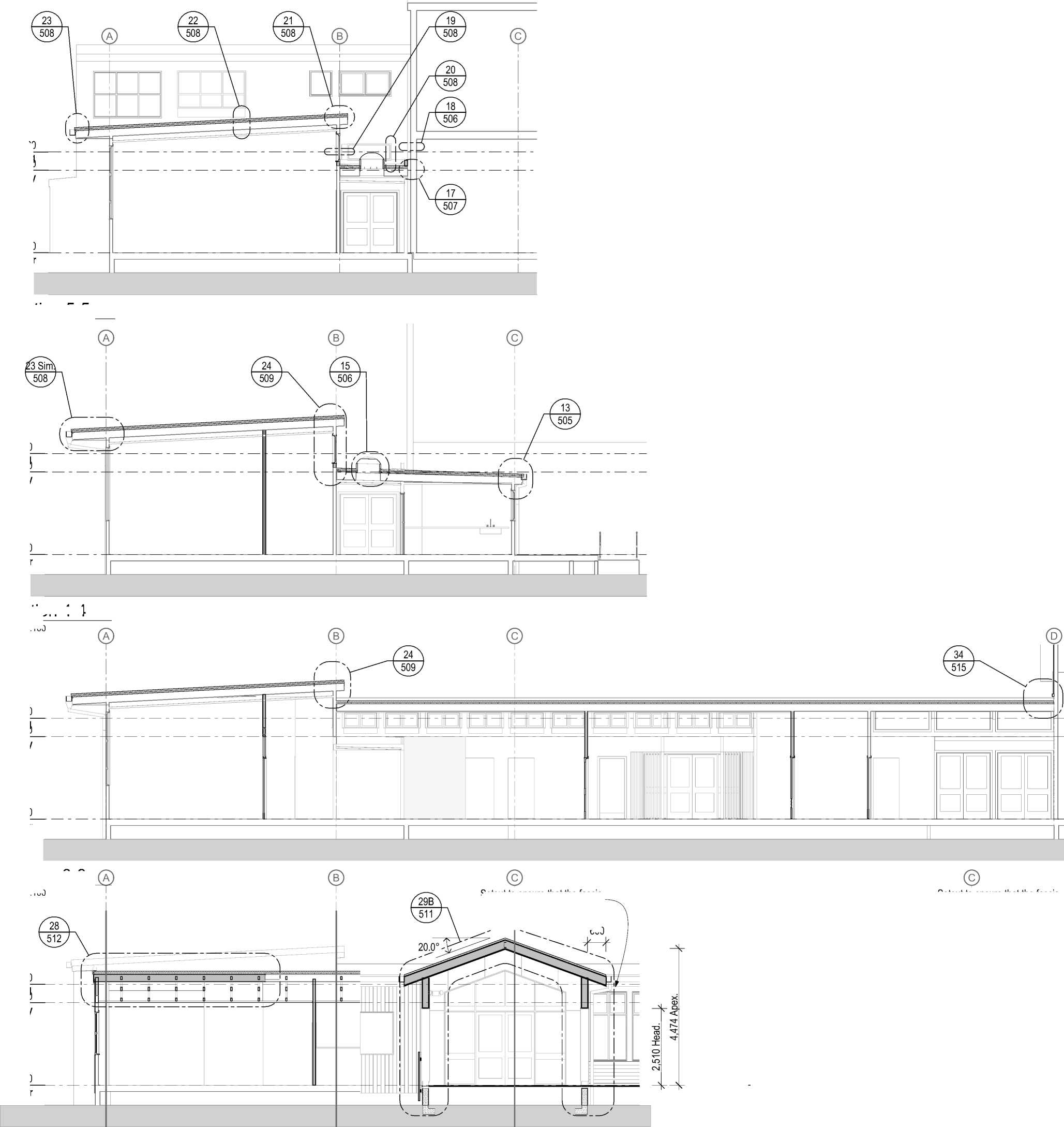
600 |
+3,960
R+3o,o3f601
Section 5-5
+3,960
R+3o,o3f601
Section 4-4
Scale 1:100
+3,960
R+3o,o3f601
Section 3-3
Scale 1:100
+3,960
R+3o,o3f601
Section 2-2
Scale 1:100
Setout to ensure that the fascia alignSsewtoituht tthoaet nosf uthre tmhatinthbeufiladsincgia.
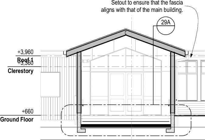 |
|
0 1m 2m |
 |
Scale 1:100 |
Section 1-1
5m
10m
1:100 - A2
The contractor shall confirm all conditions and dimensions on site before proceeding with work. Do not scale dimensions off drawings. Contractor is to report any discrepancies to the architect immediately. Plans to be read in conjunction with the specification. RIA accepts no responsibility for any changes made to the issued documents.
| |||||||||||||||||||||||||||||||||||||||||||||
|
Copyright RESOLVEiTARCHITECTS 2022© |
RESOLVE';
ARCHITECTS
LEVEL 1, 171 VIVIAN STREET, TE ARO
PO BOX 9792, WELLINGTON
RESOLVEiTARCHITECTS.CO.NZ
Client:
Naenae College
Project Name:
Project Number: R21112
Naenae College
Administration Exterior
Project Address:
910 High Street Avalon Hutt City
Status: WRP Review & ProcurDate:t 15/08/2022
Scale: 1:100
Drawing No.
300
Size:
Revision No.
A
CAD File: S:\Projects\R21112 - Naenae College Roof Remediation\A-Cad\R21112 Naenae College Admin Block-Developed Design 220727.pln
The contractor shall confirm all conditions and dimensions on site before proceeding with work. Do not scale dimensions off drawings. Contractor is to report any discrepancies to the architect immediately. Plans to be read in conjunction with the specification. RIA accepts no responsibility for any changes made to the issued documents.
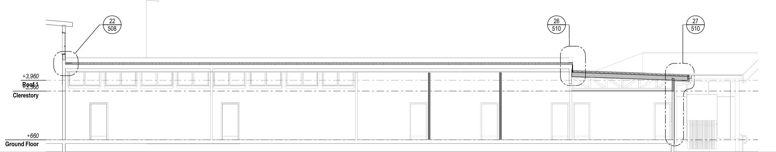
| |||||||||||||||||||||||||||||||||||||||||||||
|
Copyright RESOLVEiTARCHITECTS 2022© |
A
Section A-A
Scale 1:100
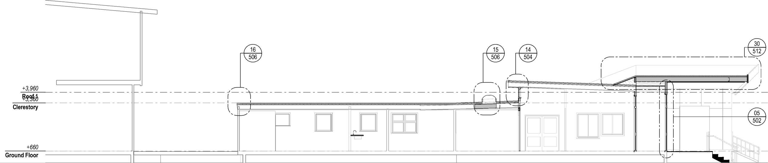
RESOLVE';
ARCHITECTS
LEVEL 1, 171 VIVIAN STREET, TE ARO
PO BOX 9792, WELLINGTON
RESOLVEiTARCHITECTS.CO.NZ
Client:
Naenae College
Section B-B
Scale 1:100
Project Name:
Project Number: R21112
Naenae College
Administration Exterior
Project Address:
910 High Street Avalon Hutt City
Drawing Title:
Sections
|
Status: WRP Review & ProcurDate:t 15/08/2022 Scale: 1:100 Size: | ||||||||||||||
|
CAD File: S:\Projects\R21112 - Naenae College Roof Remediation\A-Cad\R21112 Naenae College Admin Block-Developed Design 220727.pln
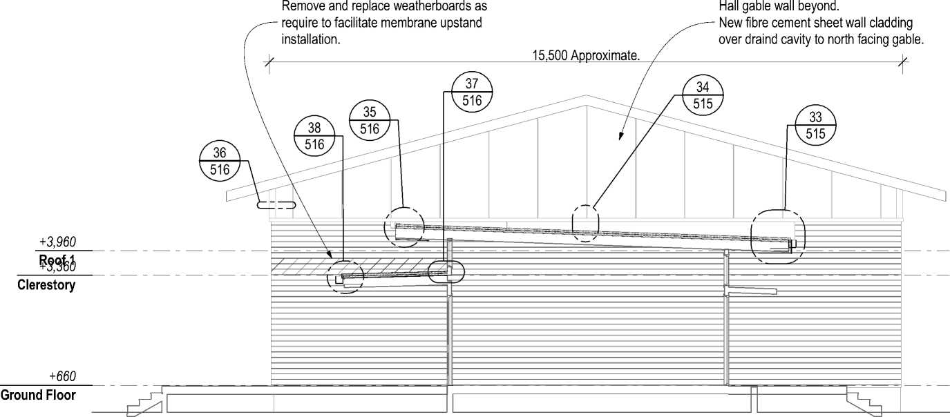
The contractor shall confirm all conditions and dimensions on site before proceeding with work. Do not scale dimensions off drawings. Contractor is to report any discrepancies to the architect immediately. Plans to be read in conjunction with the specification. RIA accepts no responsibility for any changes made to the issued documents.
| |||||||||||||||||||||||||||||||||||||||||||||
|
Copyright RESOLVEiTARCHITECTS 2022© |

Section E-E
Scale 1:100
+3,960
R+3o,o3f6 01
Clerestory
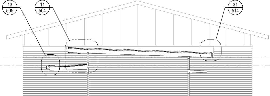
+660
Ground Floor


Section D-D
Scale 1:100
+3,960
R+3o,o3f6 01
Clerestory
+660
Ground Floor
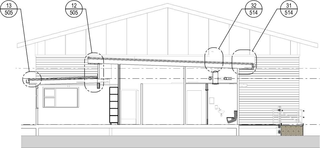
RESOLVE1;
ARCHITECTS
fed
LEVEL 1, 171 VIVIAN STREET, TE ARO
PO BOX 9792, WELLINGTON
RESOLVEiTARCHITECTS.CO.NZ
Client:
Naenae College
Project Name: Project Number: R21112
Naenae College
Administration Exterior
Project Address:
910 High Street Avalon Hutt City
Section C-C
Scale 1:100
Drawing Title:
Sections
|
Status: WRP Review & ProcurDate:t 15/08/2022 Scale: 1:100 Size: A2 | ||||
|
CAD File: S:\Projects\R21112 - Naenae College Roof Remediation\A-Cad\R21112 Naenae College Admin Block-Developed Design 220727.pln
|
Hand rail bracket fixed to posts. Galvanised steel handrail. 300 Min. Existing stair (Indicative) 300 Min. Hand rail bracket fixed to posts. 1,200 Min. Tread width. +660 +660 Ground Floor Ground Floor Side fixed posts Section H-H Scale 1:20 Stanchion set into concrete footing. Dressed timber edge board H3.2 with 20 Gap to ramp. Stanchion extends below deck level and fixed to structural members. Paling: 45x45, Dressed timber H3.2, with equal gaps of 30mm approx. Galvanised steel railing with handrail and mid-rail, Posts equi-spaced at 1275 approx. Galvanised steel plate edge with 20 Gap to ramp. Support stair base with Bowmac Angle stainless steel BS175 Galvanised steel handrail. Slope Posts and Palings 5° Ramp structure: Refer to Structural Engineer's documentation. H 111 |
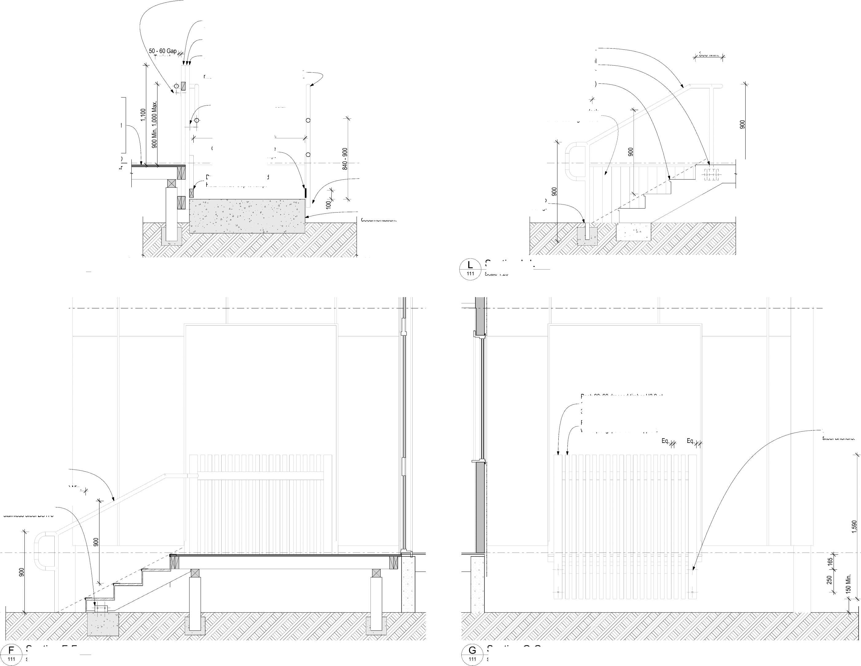
Scale 1:20 |
|
Section F-F Section G-G Scale 1:20 0 0.25m 0.5m 1m ru i___________i 1:20 - A2 |
Deck Design (NZS 3604 3kPa Floor Loading)
Decking: 88 x32 H3.2
Joist: 140x45 Min. SG8 H3.2, (Span 2.15m Max).
Bearer: 90x90 SG8 H3.2, Span 1,300 Max. Loaded dimension 1,000 Max.
Pile: 125x125 H5
Footing Concrete: 225x225x200 Min
300 Min.
Typical.
Post: 90x90 dressed timber H3.2 at 1,350 centres approx, fastened to boundary joists fastened to deck structure with S.S. fixings.
The contractor shall confirm all conditions and dimensions on site before proceeding with work. Do not scale dimensions off drawings. Contractor is to report any discrepancies to the architect immediately. Plans to be read in conjunction with the specification. RIA accepts no responsibility for any changes made to the issued documents.
Dress exposed sides of deck with vertical decking timbers
Section L-L
Post: 90x90 dressed timber H3.2 at 1450mm centres approx, Gap to opening 30mm approx.
Paling: 45x45, Dressed timber H3.2, with equal gaps of 30mm approx.
| |||||||||||||||||||||||||||||||||||||||||||||
|
Copyright RESOLVEiTARCHITECTS 2022© |
ELEVATIONS KEY NOTES:
REFER SHEET 001
Post fastened to concrete foundation with stainless steel anchors.
RESOLVE1;
ARCHITECTS
LEVEL 1, 171 VIVIAN STREET, TE ARO
PO BOX 9792, WELLINGTON
RESOLVEiTARCHITECTS.CO.NZ
Client:
Naenae College
Project Name:
Project Number: R21112
Naenae College
Administration Exterior
Project Address:
910 High Street Avalon Hutt City
|
Scale: 1:20 Size: A2 Drawing Title: Status: WRP Review & ProcurDate:t 15/08/2022 | ||||
|
CAD File: S:\Projects\R21112 - Naenae College Roof Remediation\A-Cad\R21112 Naenae College Admin Block-Developed Design 220727.pln
The contractor shall confirm all conditions and dimensions on site before proceeding with work. Do not scale dimensions off drawings. Contractor is to report any discrepancies to the architect immediately. Plans to be read in conjunction with the specification. RIA accepts no responsibility for any changes made to the issued documents.
| |||||||||||||||||||||||||||||||||||||||||||||
|
Copyright RESOLVEiTARCHITECTS 2022© |
Post: 90x90 dressed timber H3.2 at 1,350 centres approx, fastened to boundary joists fastened to deck structure with S.S. fixings.
Paling: 45x45, Dressed timber H3.2, with equal gaps of 30mm approx.
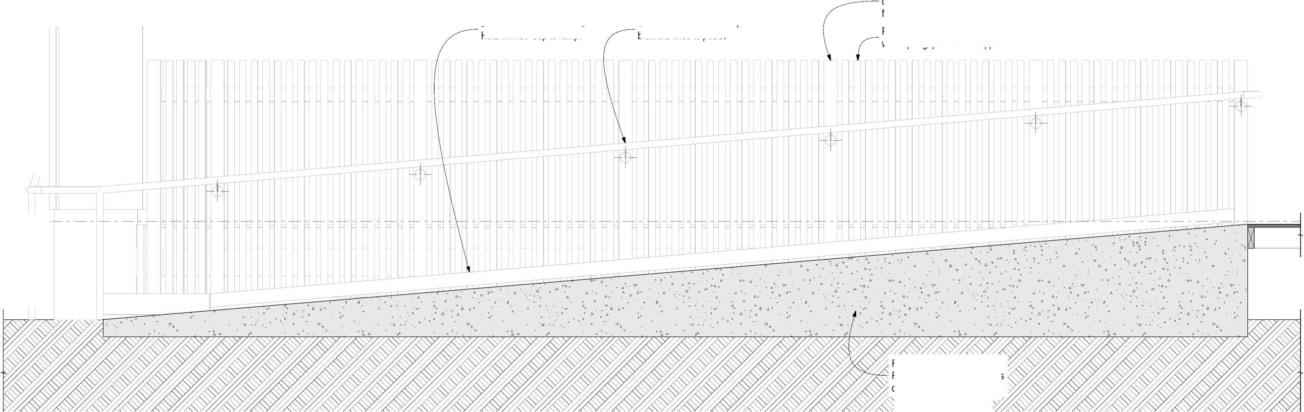
Dressed timber edge board H3.2 with 20 Gap to ramp.
Galvanised steel hand rail, brackets fixed to posts.
ELEVATIONS KEY NOTES:
REFER SHEET 001

Section J-J
Scale 1:20
Ramp structure:
Refer to Structural Engineer's documentation.
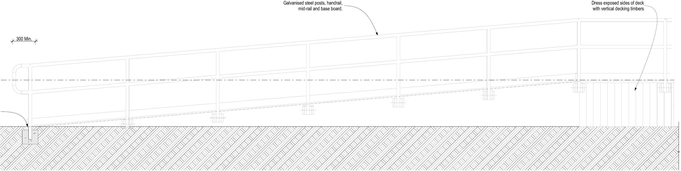
300 Min Dress exposed sides of deck with vertical decking timbers Galvanised steel posts, handrail mid-rail and base board |
RESOLVE1;
ARCHITECTS
LEVEL 1, 171 VIVIAN STREET, TE ARO
PO BOX 9792, WELLINGTON
RESOLVEiTARCHITECTS.CO.NZ
Client:
Naenae College
Project Name: Project Number: R21112
Naenae College
Administration Exterior
Project Address:
910 High Street Avalon Hutt City

0 0.25m 0.5m 1m
ru i___________i 1:20 - A2
|
Drawing Title: Status: WRP Review & ProcurDate:t 15/08/2022 Scale: 1:20 Size: A2 | ||||
|
CAD File: S:\Projects\R21112 - Naenae College Roof Remediation\A-Cad\R21112 Naenae College Admin Block-Developed Design 220727.pln

Exterior wall cladding, fibre cement sheet.
|
Flashing tape Existing wall framing, add addition studs to support sheet joints as per cladding manufacturers details. Powdercaoted aluminium flashing set into concrete chase. Fibre cement panel wall cladding installed vertically over H3.1 timber cavity battens. Paint finish. Continuous sealant bead over PEF rod. | 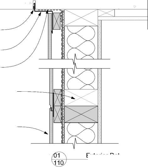 |
|
Exterior Detail 1:5 | |
Flashing tape over head flashing.
Cavity batten blocking 100mm @ 5°, H3.1.
uPVC cavity closer Cacity batten at sheet joints. Powdercoated aluminium head flashing BMT 0.9 Min. with stpoends, extend 20 Min. beyond joinery.
•
•
•
•
Cover to joinery 10 Min.
Gap to cladding 5 Min.
Slope 15° Min.
Cover to cladding 35 Min.
New aluminium joinery refer to Window and Door Schedule.
Flashing tape dressed into opening (all around).
|
Do not install insulation within ceiling void. Refer to Keynote 4711P on Sheet 001. |
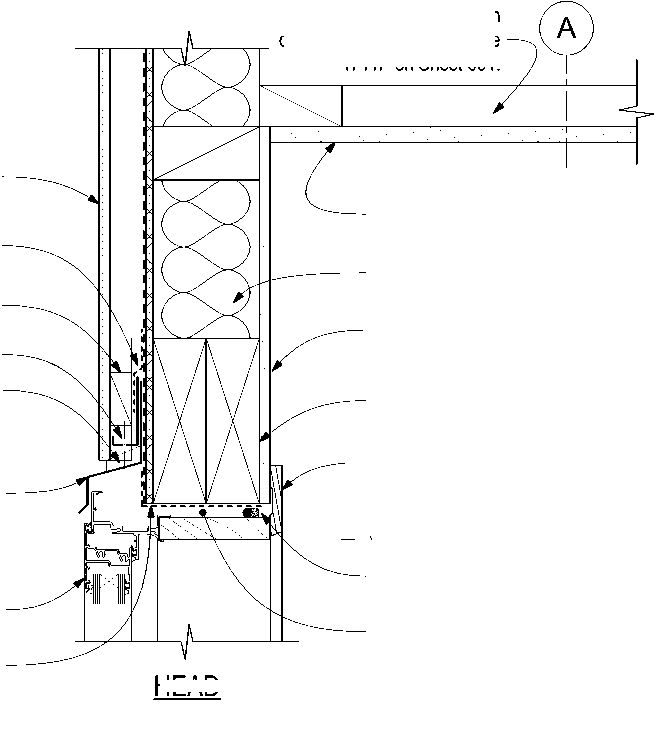
HEAD |
|
New insulation. New ceiling lining and finish. Refer to "Interiors" specification Interior lining and finish. Refer to "Interiors" specification Lintel 140x90 Min., SG8, H1.2 (NZS 3604 Table 8.9). Architrave. Refer to "Interiors" specification |
_ v_ AFFL. 2,400
Air seal: Continuous sealant bead on PEF rod
Note: Remove temporary packing from head.
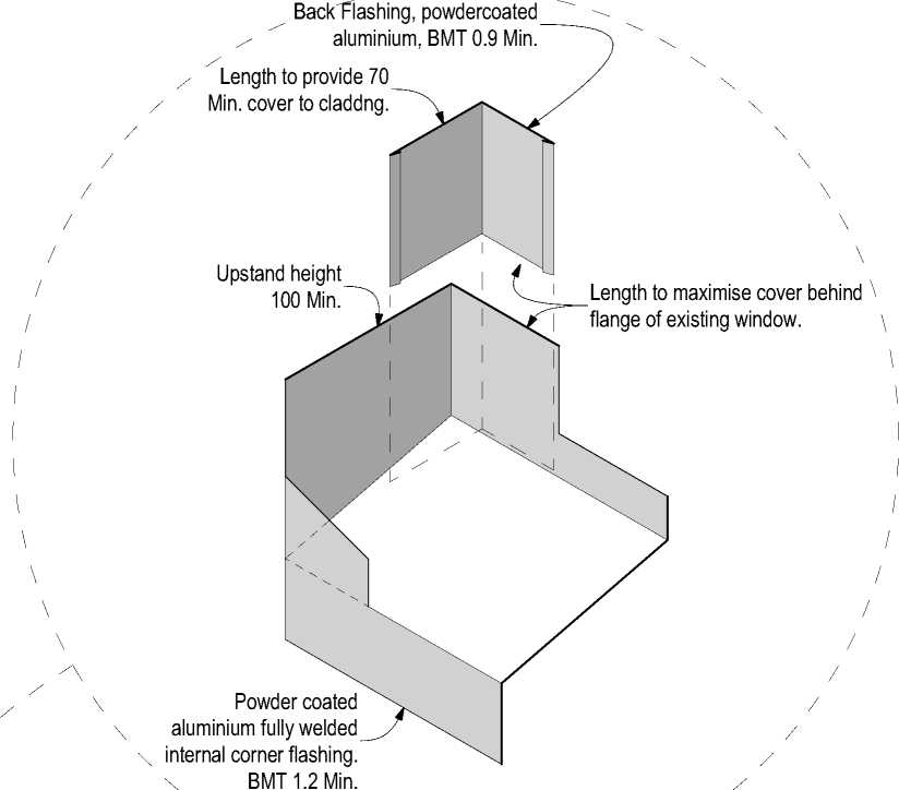 |
The contractor shall confirm all conditions and dimensions on site before proceeding with work. Do not scale dimensions off drawings. Contractor is to report any discrepancies to the architect immediately. Plans to be read in conjunction with the specification. RIA accepts no responsibility for any changes made to the issued documents. |
|
Isometric View - Flashings | |
| |||||||||||||||||||||||||||||||||||||||||||||
|
Copyright RESOLVEiTARCHITECTS 2022© |
Cladding System External Corner (Typical)
Flashing tape.
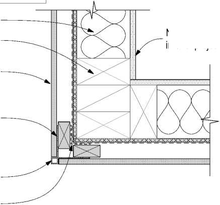


Exterior Detail
1:5
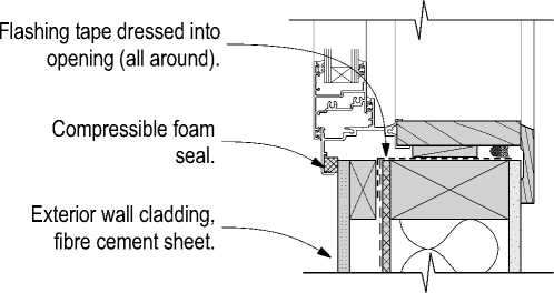
Flashing tape dressed into opening (all around).
WANZ sill support bar.
Gap 5 Min.
Cavity batten blocking 100mm @ 5°, H3.1.
Existing wall framing, add addition studs to support sheet joints as per cladding manufacturers details.
Fibre cement panel wall cladding installed vertically over H3.1 timber cavity battens. Paint finish. Extend 50mm below floor framing.
Rigid wall underal with wall underlay over. Extend 15mm below floor framing.
Flashing tape over both flashing and cavity closer.
Cavity batten blocking 100mm @ 5°, H3.1.
uPVC cavity closer Cacity batten at sheet joints. Aluminium Flashing BMT 1.2 Min. Powdercoated.
Flashing tape separation.
15° slope to top edge. Ankascrew M8 @ 600 ctrs, recess into timber
Existing concrete perimeter foundation.
|
AFFL. 1,000 Wall finish. Refer to interior project. Existing timber floor (Indicative). |
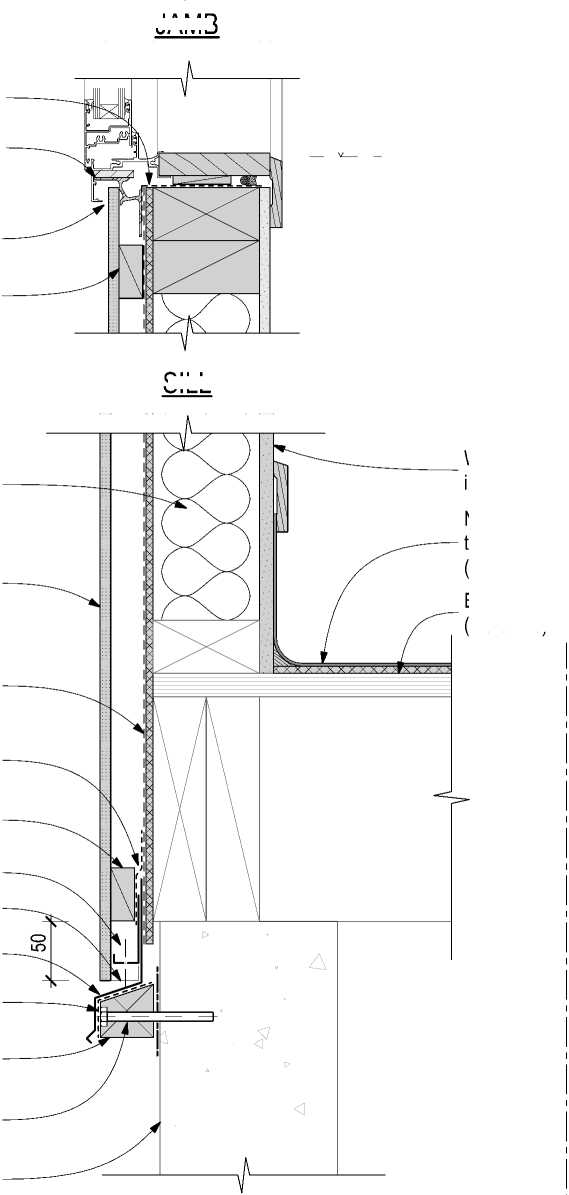
JAMB SILL |
New floor finish. Refer to interior project. (Indicative).

Cladding System Internal Corner (Typical)
Flashing tape over existing wall underlay.
Cladding and cavity batten fixing as per manufacturer's system specification.
x Back Flashing, powdercoated aluminium, BMT 0.9 Min. Continuous sealant bead.
Fully welded internal corner flashing, Refer to isometric view.
Window sill below.
Flashing tape over existing wall underlay.
Powder coated aluminium flashing BMT 0.9 Min. Terminates at bottom of cladding.
Continuous sealant bead
Scribber & cover board H3.2, Paint finish.
Line of window sill above.
Existing bevel back weatherboards remain in place. Refurbish as required.
06
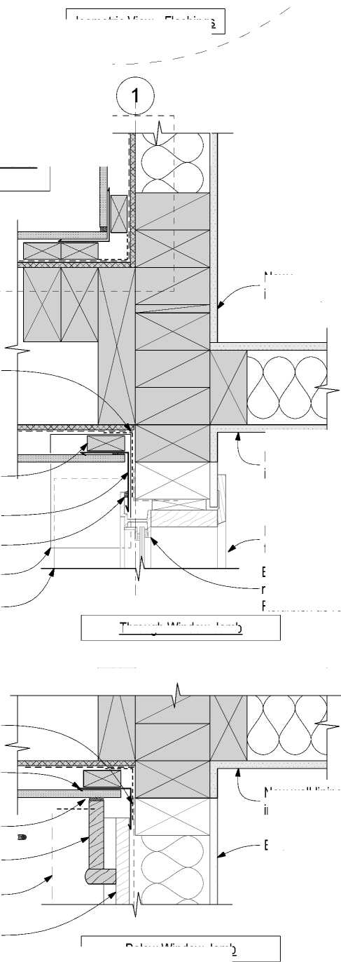
Through Window Jamb |
Existing window reveal & New wall lining. Refer interior project spec. |
|
Below Window Jamb | |
New wall lining. Refer interior project spec.
Existing steel window joinery remains in place.
Refurbish as required.
RESOLVE1:
ARCHITECTS
LEVEL 1, 171 VIVIAN STREET, TE ARO
PO BOX 9792, WELLINGTON
RESOLVEiTARCHITECTS.CO.NZ
Client:
Naenae College
Exterior Detail
1:5
New wall lining. Refer interior project spec.
Existing interior lining.
Project Name: Project Number: R21112
Naenae College
Administration Exterior
Project Address:
910 High Street Avalon Hutt City
|
Status: WRP Review & ProcurDate:t 15/08/2022 Scale: 1:5 Size: A2 | ||||
|
CAD File: S:\Projects\R21112 - Naenae College Roof Remediation\A-Cad\R21112 Naenae College Admin Block-Developed Design 220727.pln
**Provide locations for fixing future decorative features to front face and interior walls. Photograph and as-build framing prior to installing the RAB and deliver to contract administrator.

Cladding system aluminium external corner extrusion.
Fibre cement panel wall cladding installed vertically over H3.1 timber cavity battens. Paint finish.
New wall framing, H1.2
|
Double studs to be well spiked. Sealant bead 6mm. Cladding System Panel Joint (Typical) | |
|
**Double studs and cavity battens to provide fixing of future decorative features to solid timber framing. |  |
|
PFC post of portal frame (Indicative), refer to Structural Engineer's documentation. Continuous sealant bead Inseal tape 1.5mm thick Double stud and cavity battens at sheet joints as per manuufacturers specification. Future decorative features may be fixed into solid framing and sheet joint. | |
Cladding System Wall End Termination (Typical)
 |
Fibre cement panel wall cladding installed vertically over H3.1 timber cavity battens. Paint finish. Cladding system aluminium external corner extrusion. Exterior wall cladding. Rigid wall underlay with flexible wall underlay over. |
Flashing tape.
Double studs and cavity battens to provide fixing of future decorative features to solid timber framing.
Leg length 100 plus cavity and cladding. uPVC internal corner XW^ back flashing from above.
 |
Back of cavity. |
1 *—Upstand 100 Min.
J >—Cover to wall cladding 90 Min.
Continuous sealant bead to new concrete foundation.
.Leg length 100. Typical. Terminates at bottom of wall cladding.
Powder coated aluminium, BMT 1.2 Min. Fully welded Cover to wall cladding:
-
- Horizontal 75 Min.
-
- Vertical 90 Min.
Saddle Flashing Isometric
|
New wall lining. Refer interior project spec. Existing wall framing, add addition studs to support sheet joints as per cladding manufacturers details. Cladding System Internal Corner (Typical) Cladding System Panel Joint (Typical) Gap: 1 - 2mm. Cladding and cavity batten fixing as per manufacturer's system specification. Inseal tape 1.5mm. Continuous sealant bead. Flashing tape to RAB junction. Gap 6mm, continuous sealant bead. Upstand of Saddle flashing below. |
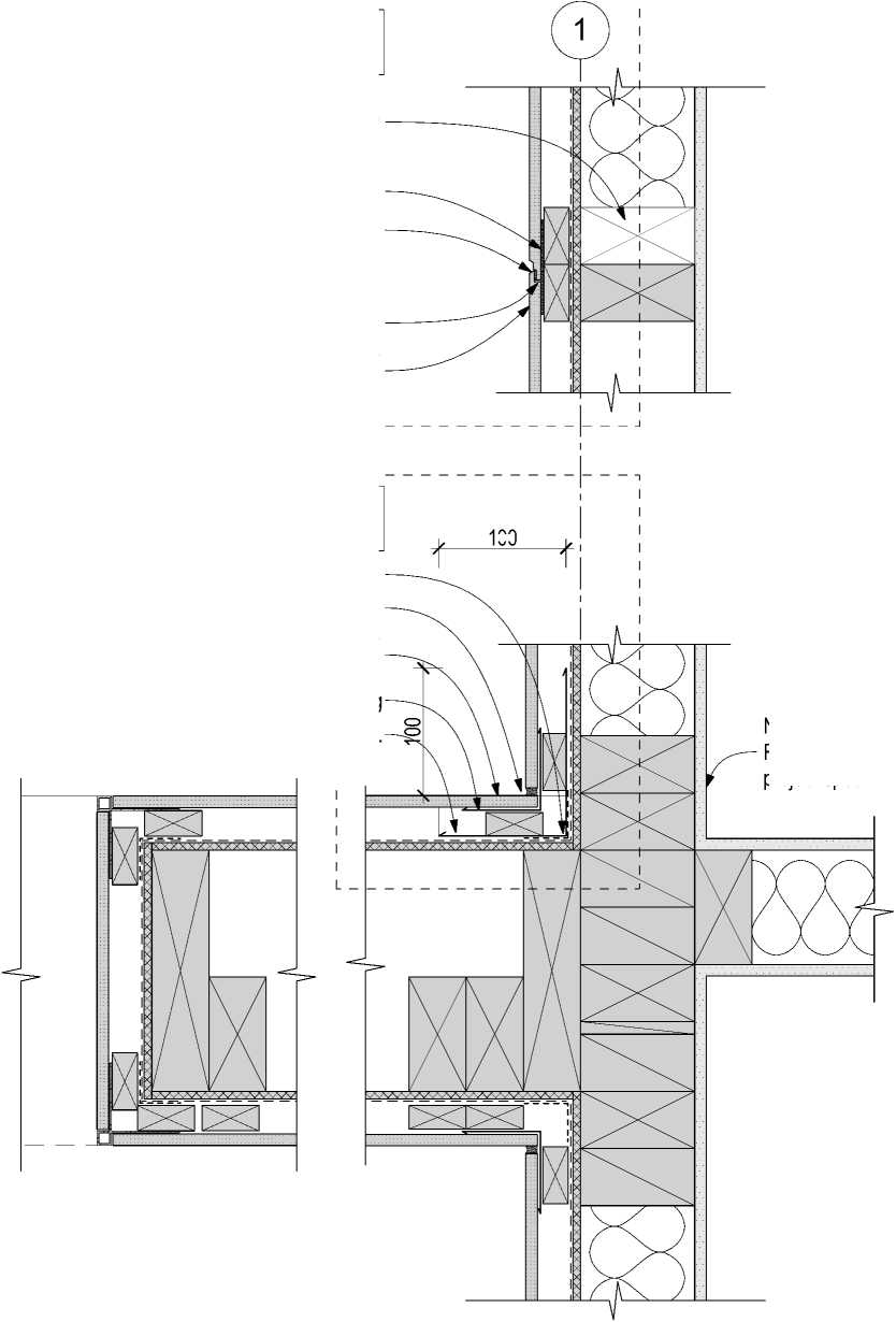
100 |
Cladding and cavity batten fixing as per manufacturer's system specification.
uPVC corner back flashing
|
Temporary EPS formwork, to be removed post concrete cure. Gap 6mm, continuous sealant bead. Flashing tape to isolate flashing and concrete and seal internal corner. Saddle flashing located at back of cavity and terninates at bottom of wall cladding. Powder coated aluminium saddle flashing, fully welded BMT 1.2 Min. Refer to isometric view. | 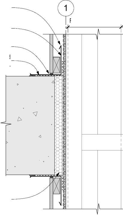 |
Foundation wall below
Section B-B / Detail 29.
Internal Corner Below Deck Level
The contractor shall confirm all conditions and dimensions on site before proceeding with work. Do not scale dimensions off drawings. Contractor is to report any discrepancies to the architect immediately. Plans to be read in conjunction with the specification. RIA accepts no responsibility for any changes made to the issued documents.
| |||||||||||||||||||||||||||||||||||||||||||||
|
Copyright RESOLVEiTARCHITECTS 2022© |

RESOLVE1;
ARCHITECTS
LEVEL 1, 171 VIVIAN STREET, TE ARO
PO BOX 9792, WELLINGTON
RESOLVEiTARCHITECTS.CO.NZ
Client:
Naenae College
Project Name: Project Number: R21112
Naenae College
Administration Exterior
Project Address:
910 High Street Avalon Hutt City
|
Status: WRP Review & ProcurDate:t 15/08/2022 Scale: 1:5 Size: A2 | ||||
|
CAD File: S:\Projects\R21112 - Naenae College Roof Remediation\A-Cad\R21112 Naenae College Admin Block-Developed Design 220727.pln
New aluminium joinery mechanism.
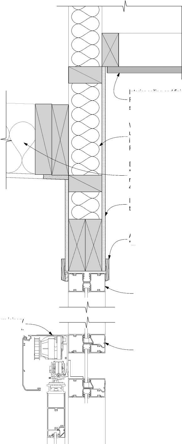 |
Wall insulation to extend continuously up to the underside of the new insulated overlay roof system. Typical. Refer to Keynote 4711P on Sheet 001. New aluminium joinery (Indicative) Refer to Window and Door Schedule. Existing insulation *Remove if practical to remove, Refer to Keynote 4711P on Sheet 001. |
|
New aluminium joinery refer to Window and Door Schedule. Architrave. Refer to "Interiors" specification Interior lining and finish. Refer to "Interiors" specification | |
Interior ceiling and finish. Refer to "Interiors" specification
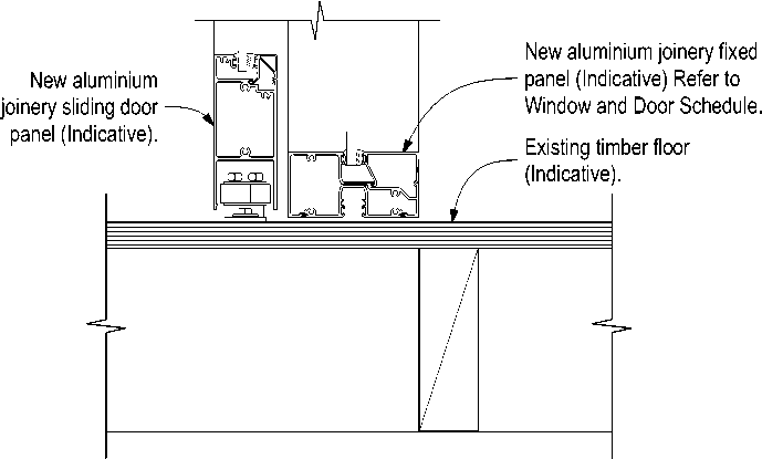
Air seal: Continuous sealant bead on PEF rod
Interior floor covering. Refer to "Interiors" specification
Fibre cement sheet 6mm Min. to create rigid backing for flashing tape.
Existing timber floor (Indicative).

Through Interior Wind Lobby Sliding Door
|
Soffit lining. Top of cavity ventilation Gap 5mm. Vent batten. Flashing tape dressed into Interior lining and finish. Refer to "Interiors" specification JAMB Door leaf New timber decking, Notation as per adjacent detail. New aluminium joinery refer to Window and Door Schedule. Possible future decorative feature shown dashed. Architrave. Refer to "Interiors" specification Soffit Battens: 90x45 H1.2 @ 600 ctrs Fixing Type "U" (1/14g x 100mm self-drilling type 17 screw). Note: Over sized to provide fixing of future decorative features to solid timber framing. New entrance canopy roof structure. Air seal: Continuous sealant bead on PEF rod | ||
|
Architrave. Refer to "Interiors" specification Interior lining and finish. Refer to "Interiors" specification Air seal: Continuous sealant bead on PEF rod Note: Remove temporary packing from head. Interior ceiling and finish. Refer to "Interiors" specification Wall insulation to extend continuously up to the underside of the new insulated overlay roof system. Typical. Refer to Keynote 4711P on Sheet 001. | 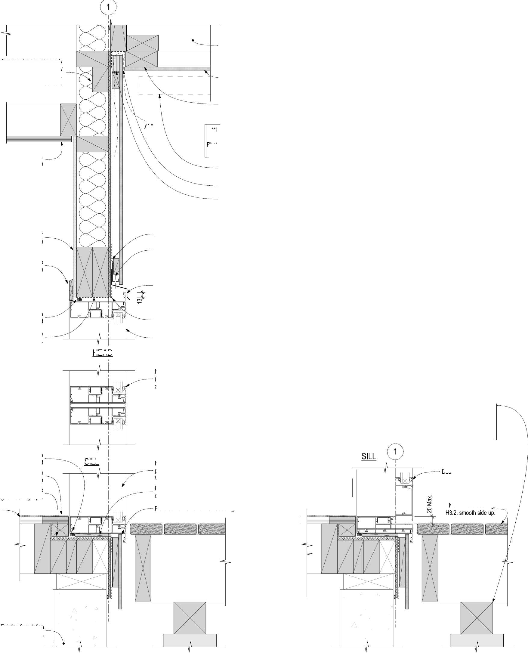
HEAD SILL |
uPVC cavity closer Powdercoated aluminium head flashing BMT 0.9 Min. • • • • Flashing tape over head flashing. New aluminium joinery (Indicative) Refer to Window and Door Schedule. Cover to joinery 10 Min. Gap to cladding 5 Min. Slope 15° Min. Cover to cladding 35 Min. Flashing tape dressed into opening (all around). New aluminium joinery refer to Window and Door Schedule. |
|
Existing foundation (Indicative). | ||
Airflow
Provide locations for fixing future decorative features to front face and interior walls.
Photograph and as-build framing prior to installing the RAB and deliver to contract administrator.
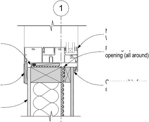 |
|
Compressible foam seal. |
Deck Specification
Design load: 3kPa as per MOE requirements.
(NZS 3604 3kPa Floor Loading)
Decking: 88 x32 H3.2
Joist: 140x45 Min. SG8 H3.2, (Span 2.15m Max).
Bearer: 90x90 SG8 H3.2, Span 1,300 Max. Loaded dimension 1,000 Max.
Pile: 125x125 H5
Footing Concrete: 225x225x200 Min
Stringers 140x45 Min. H3.2 Bolts M12 at 0.7m centres Max.
The contractor shall confirm all conditions and dimensions on site before proceeding with work. Do not scale dimensions off drawings. Contractor is to report any discrepancies to the architect immediately. Plans to be read in conjunction with the specification. RIA accepts no responsibility for any changes made to the issued documents.
| |||||||||||||||||||||||||||||||||||||||||||||
|
Copyright RESOLVEiTARCHITECTS 2022© |
New aluminium joinery fixed panel (Indicative) Refer to Window and Door Schedule.
Flashing tape dressed into opening (all around).
Fibre cement exterior wall cladding.
Through Side Light
Through Door Leaf
RESOLVE1:
ARCHITECTS
LEVEL 1, 171 VIVIAN STREET, TE ARO
PO BOX 9792, WELLINGTON
RESOLVEiTARCHITECTS.CO.NZ
Client:
Naenae College
Project Name: Project Number: R21112
Naenae College
Administration Exterior
Project Address:
910 High Street Avalon Hutt City
|
Status: WRP Review & ProcurDate:t 15/08/2022 Scale: 1:5 Size: A2 | ||||
|
CAD File: S:\Projects\R21112 - Naenae College Roof Remediation\A-Cad\R21112 Naenae College Admin Block-Developed Design 220727.pln
Lintel 140x90 Min., SG8, H1.2 (NZS 3604 Table 8.9).
|
Sill tray upstand 8 Min. New wall lining. Refer interior project spec. Flashing tape to junction of new RWU and existing soffit. Architrave. Refer to "Interiors" specification | ||
|
Interior lining and finish. Refer to "Interiors" specification Air seal: Continuous sealant bead on PEF rod Note: Remove temporary packing from head. | 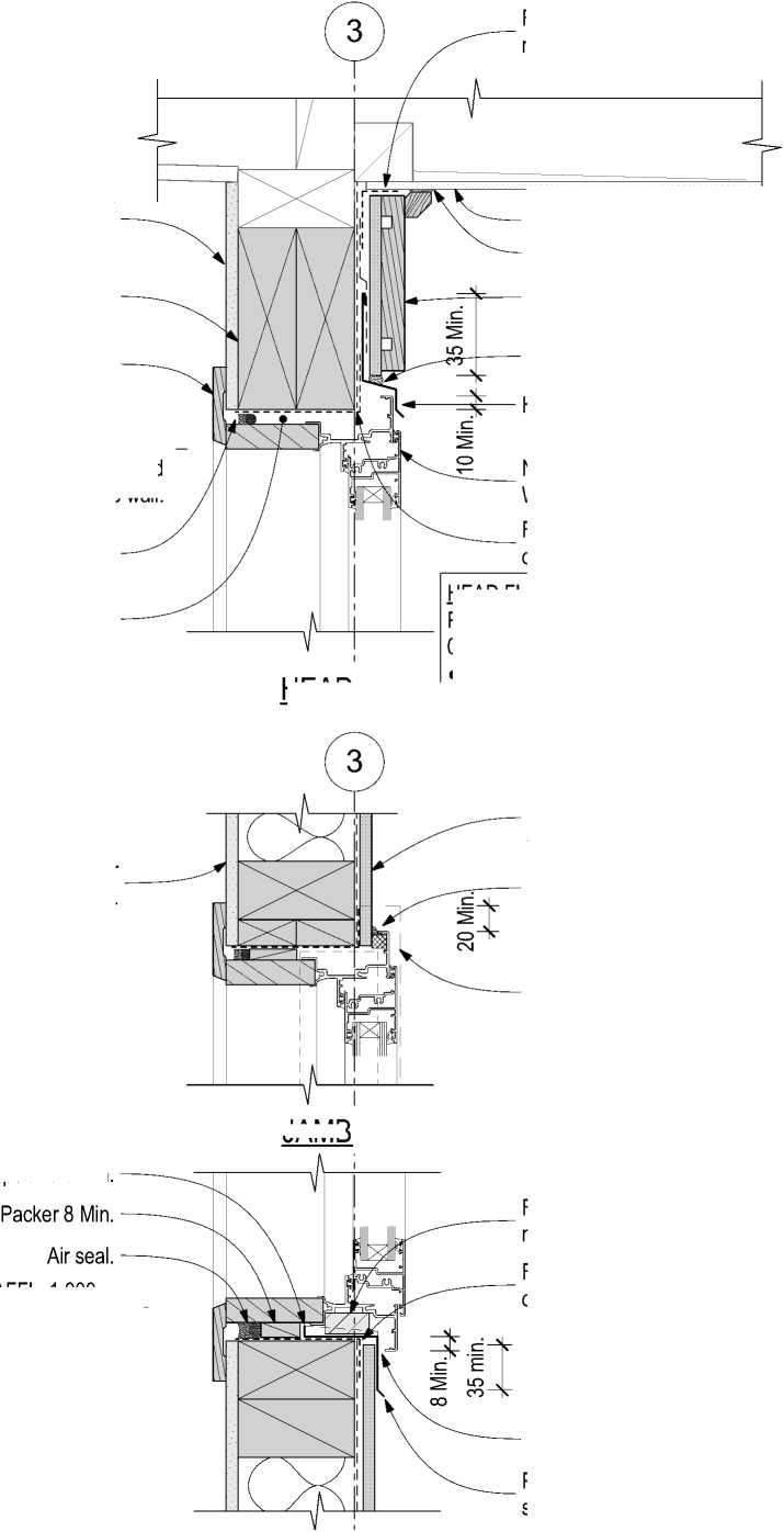
JAMB |
• • • • Cover to joinery 10 Min. Gap to cladding 5 Min. Slope 15° Min. Cover to cladding 35 Min. New fibre cement sheet wall cladding to match adjacent existing wall cladding. Paint finish. Continuous protective sealant bead. HEAD FLASHING Powdercoated aluminium head flashing BMT 0.9 Min. extend 20 Min. beyond joinery. |
|
Head flashing above. AFFL. 1,000 New aluminium joinery refer to Window and Door Schedule. Flashing tape dressed into opening (all around). Frame block by window manufacturer Flashing tape dressed into opening (all around). Gap 5 Min. Powdercoated aluminium sill tray BMT 0.9 Min. | ||
*AFFL. 2,150-V__
* Match existing retained window on same wall.
HEAD
SILL
Existing fibre cement soffit retained. Continuous sealant bead.
New Cover board H3.2. over fibre cement sheet cladding.
50mm sealant bead to each end of head flashing.
Head flashing
Architrave. Refer to
"Interiors" specification
*AFFL. 2,150_v_
* Match existing retained window on same wall.
|
Flashing tape to junction of new RWU and existing soffit. | |
|
Interior lining and finish. Refer to "Interiors" specification Air seal: Continuous sealant bead on PEF rod Note: Remove temporary packing from head. Lintel 240x70 Min. SG8, H1.2 (NZS 3604 Table 8.9). *Available space may necessitate a steel beam C.O.S. | 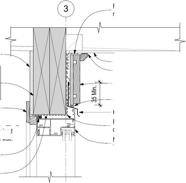 |
|
• • • • Cover to joinery 10 Min. Gap to cladding 5 Min. Slope 15° Min. Cover to cladding 35 Min. New aluminium joinery refer to Window and Door Schedule. HEAD FLASHING Powdercoated aluminium head flashing BMT 0.9 Min. extend 20 Min. beyond joinery. | |
HEAD
The contractor shall confirm all conditions and dimensions on site before proceeding with work. Do not scale dimensions off drawings. Contractor is to report any discrepancies to the architect immediately. Plans to be read in conjunction with the specification. RIA accepts no responsibility for any changes made to the issued documents.
Existing fibre cement soffit retained. Continuous sealant bead.
New Cover board H3.2. over fibre cement sheet cladding.
50mm sealant bead to each end of head flashing.
Head flashing
Flashing tape dressed into opening (all around).
|
New wall lining. Refer interior project spec. | 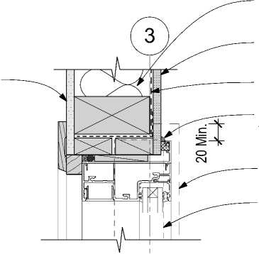 |
New wall insulation.
New fibre cement sheet wall cladding to match adjacent existing wall cladding. Paint finish.
New wall underlay.
Continuous protective sealant bead.
Head flashing above.
Sill Tray below shown hidden.
JAMB

| |||||||||||||||||||||||||||||||||||||||||||||
|
Copyright RESOLVEiTARCHITECTS 2022© |
|
Existing wall lining. Refer interior project spec. | |
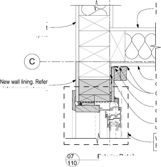 |
Existing interior wall lining. Refer interior project spec. Window jamb detail. Refer to Detail 8. |
|
interior project spec. Exterior Detail 1:5 | |
Existing exterior wall cladding (No Change).
.Continuous sealant bead.
Powdercoated aluminium inte corner back flashing BMT 0.9 Lap new and existing wall underlay, flashing tape to lap.
|
New wall insulation. Wall finish. Refer to New wall underlay. Existing timber floor (Indicative). |
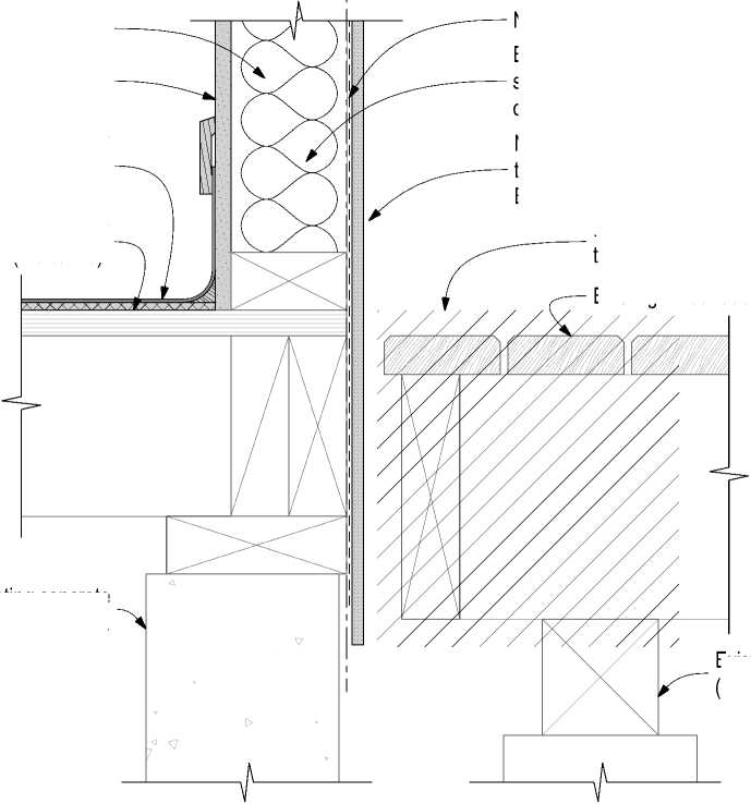 |
New floor finish. Refer to interior project. (Indicative).
Existing wall framing, add addition studs to support sheet joints as per cladding manufacturers details.
New fibre cement sheet exterior wall cladding to match adjacent existing wall cladding.
Extend 50mm below floor framing. Paint finish.
Remove timber decking as required to install new wall cladding.
Existing timber deck (Indicative).
dressed into opening (all around).
*Flush threshold.
cement sheet 6mm Min. to create rigid backing for flashing tape.
Interior floor covering. Refer to "Interiors" specification
Existing timber floor (Indicative).
Existing concrete perimeter foundation.
SILL
Sill tray upstand 8 Min.
Frame block by window manufacturer *Set door sill height to achieve 20mm Max. to exisiting deck level.
Remove timber decking as required to install new wall cladding.
Existing timber deck (Indicative).
Gap 12 Min
Gap 5 Min.
Powdercoated aluminium sill tray BMT 0.9 Min.
Fibre cement exterior wall cladding.
Paint finish

Exterior Detail
1:5
Existing foundation (Indicative).
Existing foundation (Indicative).
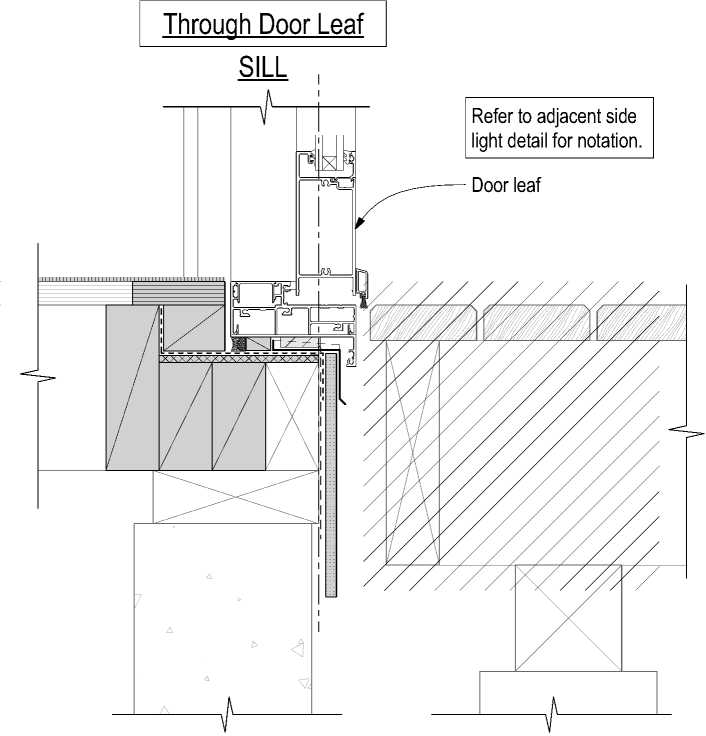
RESOLVE
ARCHITECTS

LEVEL 1, 171 VIVIAN STREET, TE ARO
PO BOX 9792, WELLINGTON
RESOLVEiTARCHITECTS.CO.NZ
Client:
Naenae College
Project Name: Project Number: R21112
Naenae College
Administration Exterior
Project Address:
910 High Street Avalon Hutt City

Exterior Detail
1:5
|
Status: WRP Review & ProcurDate:t 15/08/2022 Scale: 1:5 Size: A2 | ||||
|
CAD File: S:\Projects\R21112 - Naenae College Roof Remediation\A-Cad\R21112 Naenae College Admin Block-Developed Design 220727.pln

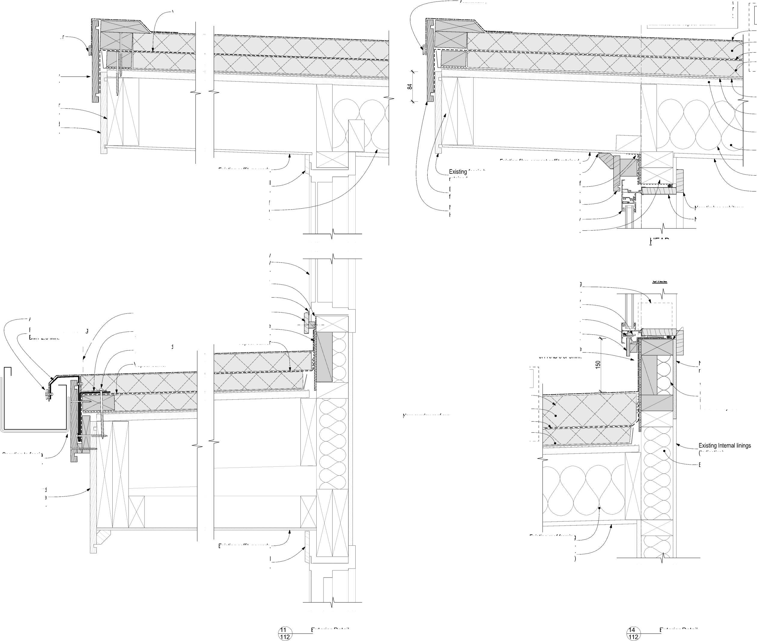
Aluminium pressure bar
Folded aluminium flashing BMT 2.0 Min.
Trim existing metal roofing to this line.
Extruded aluminium angle cleat Ex. 75x50x3.
Screw fix to solid timber framing.
Vapour barrier
Existing soffit, no work.
fascia board retained if suitable C.O.S.
Existing fibre cement soffit retained.
Continuous sealant bead.
Flashing tape to junction of new RWU and existing soffit.
Timber facing board, continuous across length of wall.
New window joinery
Existing timber structure (Indicative).
HEAD
New timber architrave
Overlay roof system
PIR board.
New vapour barrier
PIR infill fillet.
Existing tray profile roof cladding to remain.
Existing original membrane containing asbestos.
Existing original roof substrate (Indicative).
Existing roof structure (Indicative).
The contractor shall confirm all conditions and dimensions on site before proceeding with work. Do not scale dimensions off drawings. Contractor is to report any discrepancies to the architect immediately. Plans to be read in conjunction with the specification. RIA accepts no responsibility for any changes made to the issued documents.
| |||||||||||||||||||||||||||||||||||||||||||||
|
braneight RESOLVEiTARCHITECTS 2022© |
Existing insulation *Remove if practical to remove, Refer to Keynote 4711P on Sheet 001.
Existing ceiling lining(Indicative).
Existing timber clerestory windows over hall lobby remain in place.
Dress membrane up to maximum attainable height.
Continuous sealant bead.
New timber trim to replace existing removed.
New upstand substrate JH RAB 6 or 9mm.
Vapour barrier
Membrane dressed into opening and extend up framing 100 Min.
Frame block by window manufacturer
WANZ sill support bar.
Fibre cement wall cladding, Paint finish.
New upstand substrate JH RAB 6 or 9mm.
PIR board (tapered) to achieve pitch of 2° Nom.
New vapour barrier
SILL
Wall insulation to extend continu up to the underside of the new insulated overlay roof system. T Refer to Keynote 4711P on She
Existing framing (Indicative)
|
New timber infill framing to raise window sill within existing openin | 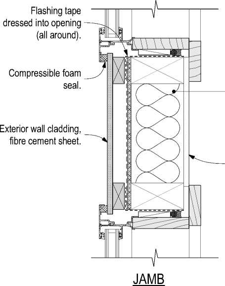 |
Existing framing. (Indicative) |
RESOLVE';
ARCHITECTS
LEVEL 1, 171 VIVIAN STREET, TE ARO
PO BOX 9792, WELLINGTON
RESOLVEiTARCHITECTS.CO.NZ
Client:
Naenae College
Project Name: Project Number: R21112
Naenae College
Administration Exterior
Project Address:
910 High Street Avalon Hutt City
Status: WRP Review & ProcurDate:t 15/08/2022
Scale: 1:5
Size: A2
Drawing No.
504
Revision No.
A
CAD File: S:\Projects\R21112 - Naenae College Roof Remediation\A-Cad\R21112 Naenae College Admin Block-Developed Design 220727.pln
New pressure bar
New fascia board, H3.2, Paint finished.
Existing timber framing (Indicative).
Existing fascia board retained if suitable C.O.S.
3
New overlay roof system installed over existing metal tray clad roof.
Existing retained metal roof cladding over original membrane (containing asbestos) and substrate.
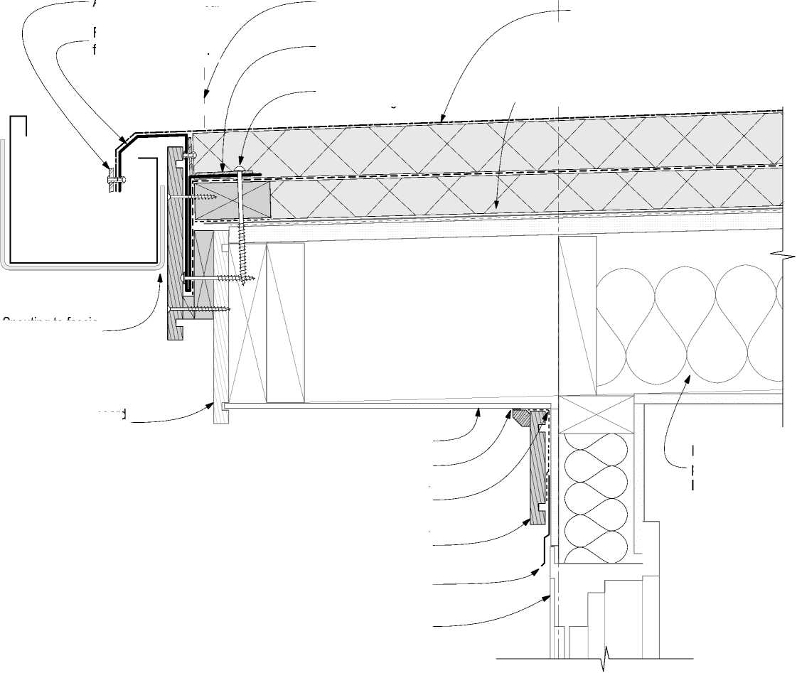
|
PIR board. Overlay roof system | ||
|
Flashing tape. Fibre cement cladding on wall underlay. Seal and paint back of sheet 150 Min. before installation Flashing tape to junction of new RWU and existing soffit. Timber facing board, continuous across length of wall. Timber packing H3.2 between windows. Existing fibre cement soffit retained. Continuous sealant bead. Extend membrane up behind cavity closer. Cavity batten blocking 100mm @ 5°, H3.1. uPVC cavity closer Cacity batten at sheet joints. | 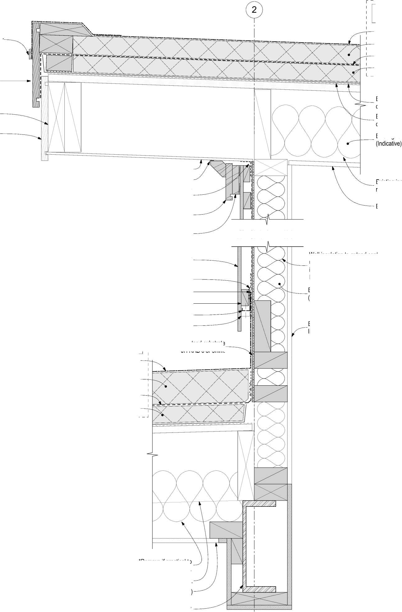 |
Single ply membrane Existing ceiling lining(Indicative). Existing tray profile roof cladding to remain. Existing original membrane containing asbestos. Existing roof structure New vapour barrier PIR infill fillet. |
|
Single ply membrane New vapour barrier PIR infill fillet. PIR board (tapered) to achieve pitch of 2° Nom. Existing Internal linings (Indicative) Overlay roof system Maximise height of PFC beam (Indicative), Refer to Structural Engineer's documentation. Existing framing (Indicative) Wall insulation to extend continuously up to the underside of the new insulated overlay roof system. Typical. Refer to Keynote 4711P on Sheet 001. Existing metal clad roof remains. New overlay roof system installed over existing metal tray clad roof. Existing insulation *Remove if practical to remove, Refer to Keynote 4711P on Sheet 001. Existing roof framing (Indicative). Existing ceiling lining. (Indicative) | ||
New upstand substrate JH RAB 6 or 9mm.
13
#LayID
Exterior Detail
1:5
12
#LayID
Exterior Detail
1:5
New overlay roof system installed over existing metal tray clad roof.
Existing insulation *Remove if practical to remove, Refer to Keynote 4711P on Sheet 001.
The contractor shall confirm all conditions and dimensions on site before proceeding with work. Do not scale dimensions off drawings. Contractor is to report any discrepancies to the architect immediately. Plans to be read in conjunction with the specification. RIA accepts no responsibility for any changes made to the issued documents.
|
Existing retained metal roof cladding over original membrane (containing asbestos) and substrate. |
| |||||||||||||||||||||||||||||||||||||||||||||
|
Copyright RESOLVEiTARCHITECTS 2022© | ||||||||||||||||||||||||||||||||||||||||||||||
RESOLVE';
ARCHITECTS
LEVEL 1, 171 VIVIAN STREET, TE ARO
PO BOX 9792, WELLINGTON
RESOLVEiTARCHITECTS.CO.NZ
Client:
Naenae College
Project Name: Project Number: R21112
Naenae College
Administration Exterior
Project Address:
910 High Street Avalon Hutt City
Status: WRP Review & ProcurDate:t 15/08/2022
Scale: 1:5 Size: A2
Drawing No. Revision No.
505 A
CAD File: S:\Projects\R21112 - Naenae College Roof Remediation\A-Cad\R21112 Naenae College Admin Block-Developed Design 220727.pln
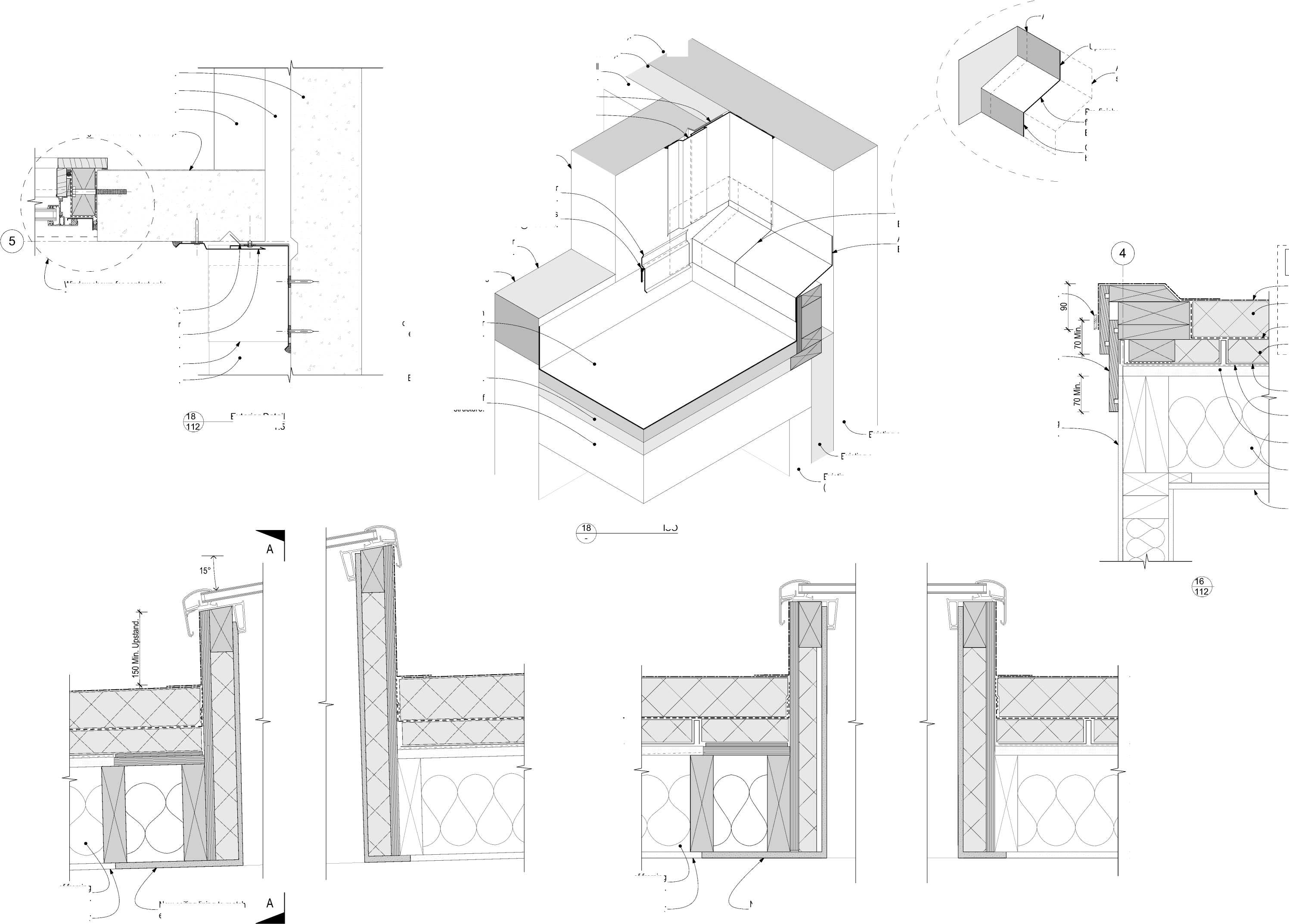
Existing siesmic gap (Indicative).
Existing timber framed wall (Indicative).
Existing siesmic flashing
New 2 piece inte(Irndailccaotirvnee)r. siesmic flashing fitted over existing. Terminates under soffit above.
1 Pre-finished steel internal corner flashing. Folded and sealed joints. BMT 0.55 Min.
Apron flashing: Pre-finished steel BMT 0.55 Min.
| |||||||||||||||||||||||||||||||||||||||||||||
|
Copyright RESOLVEiTARCHITECTS 2022© |
Window shown for context only. Refer to Detail 20.
Aluminium pressure bar.
New fascia boards, H3.2.
Exterior Detail
1:5
Existing concrete wall (Indicative).
Existing siesmic gap (Indicative).
Existing timber framed wall (Indicative).

Exterior Detail
1:5
Existing wall cladding (Indicative).
RESOLVE';
ARCHITECTS
Client:
Naenae College
Size: A2
Drawing No. Revision No.
506 A
CAD File: S:\Projects\R21112 - Naenae College Roof Remediation\A-Cad\R21112 Naenae College Admin Block-Developed Design 220727.pln

The contractor shall confirm all conditions and dimensions on site before proceeding with work. Do not scale dimensions off drawings. Contractor is to report any discrepancies to the architect immediately. Plans to be read in conjunction with the specification. RIA accepts no responsibility for any changes made to the issued documents.
|
Trim existing metal roofing to this line. Waterproof roof membrane to upstand. Waterproof roof membrane. Pre-finished steel external corner flashing. Folded and sealed joints. BMT 0.55 Min. Pre-finished steel external corner flashing. BMT 0.55 Min. Apron flashing: Pre-finished steel BMT 0.55 Min. Flashing Cover Dimensions (Typical). Horizontal 150 Min. Vertical 100 Min. Extruded aluminium angle cleat Ex. 75x50x3. Screw fix to solid timber framing. Waterproof roof membrane saddle flashing. | ||
|
Bottom edge aligns with fascia board. Pre-finished steel internal corner back flashing. BMT 0.55 Min. | 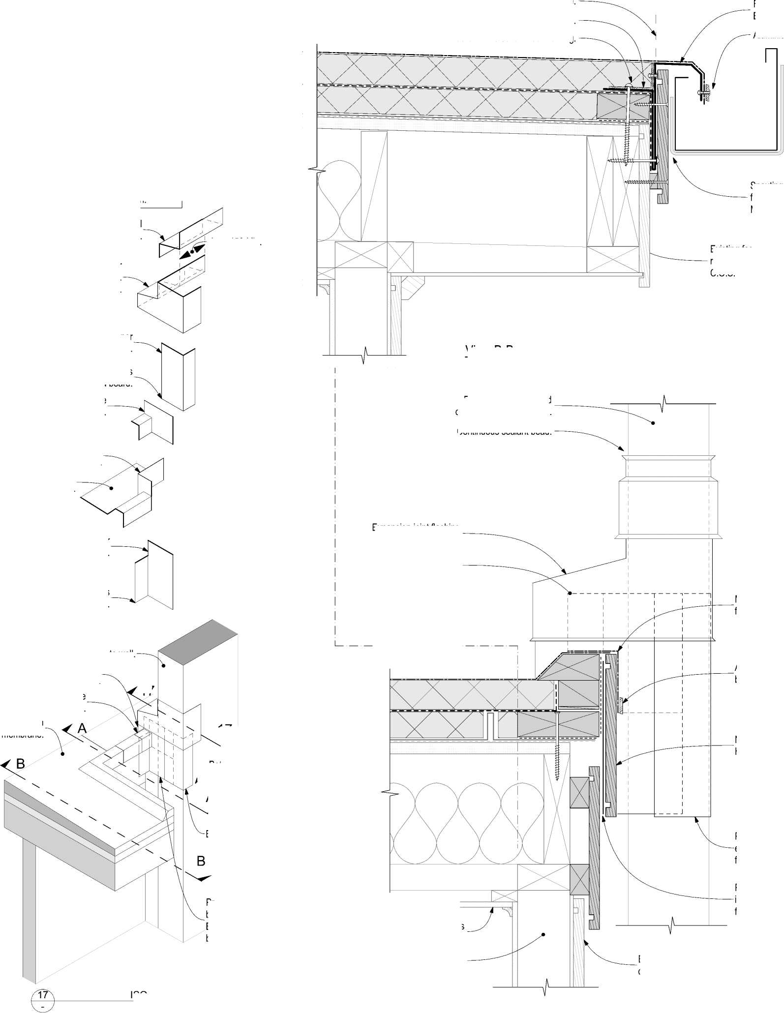
17 |
Pre-finished steel internal corner back flashing. BMT 0.55 Min. Pre-finished steel external corner flashing. BMT 0.55 Min. Folded aluminium flashing BMT 2.0 Min. |
|
17 External corner flashing. ISO View A-A New fascia board, H3.2, Paint finished. Existing cover board and wall cladding. No change. Membrane saddle flashing Pre-finished steel internal corner back flashing. BMT 0.55 Min. Bottom edge aligns with fascia board. Aluminium pressure bar Existing interior linings (Indicative). Existing structure unknown (Indicative). Bottom edge aligns with fascia board. | ||
Bottom edge aligns with fascia board.
Aluminium pressure bar
Spouting to fascia Gap 6 Min.
| |||||||||||||||||||||||||||||||||||||||||||||
|
Copyright RESOLVEiTARCHITECTS 2022© |
Lap: 150 Min.
View B-B
Existing fascia board retained if suitable C.O.S.
Existing plaster finished concrete wall. No change.
|
2,200 N.T.S. Continuous sealant bead. Cover flashing BMT 0.55 Min. Existing plaster finished concrete wall. No change. Plywood subtrate 12 Min. H3.2 CCA. Gap Est. 50mm. |
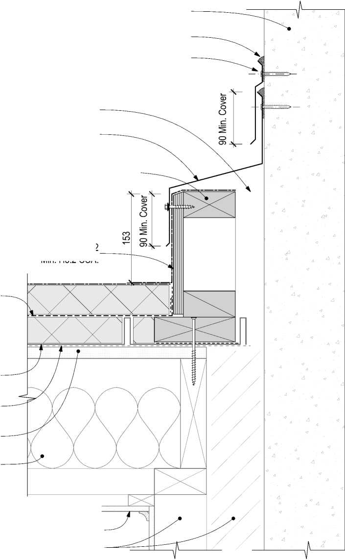 |
Apron flashing over siesmic gap BMT 0.55 Min.
New timber framed upstand (Indicative)
Confirm construction following determination of existing conditions.
New vapour barrier
Existing tray profile roof cladding to remain.
Existing original membrane containing asbestos.
Existing original roof substrate (Indicative).
Existing roof structure (Indicative).
Existing interior linings (Indicative).
ExistEinxgisstitnrugcitnutreeriuonr klinionwgns (Indicative).

Exterior Detail
1:5
Continuous sealant bead.
Expansion joint flashing BMT 0.55 Min.
Saddle flashing
Existing concrete wall. Waterproof roof membrane to upstand.
Waterproof roof membrane saddle flashing.
Waterproof roof membrane.
resolve:
ARCHITECTS
A
LEVEL 1, 171 VIVIAN STREET, TE ARO
PO BOX 9792, WELLINGTON
RESOLVEiTARCHITECTS.CO.NZ
Client:
Naenae College
Project Name: Project Number: R21112
Naenae College
Administration Exterior
Project Address:
910 High Street Avalon Hutt City
|
Status: WRP Review & ProcurDate:t 15/08/2022 Scale: 1:20, 1:5 Size: A2 | ||||
|
CAD File: S:\Projects\R21112 - Naenae College Roof Remediation\A-Cad\R21112 Naenae College Admin Block-Developed Design 220727.pln
|
Flashing Profile. |
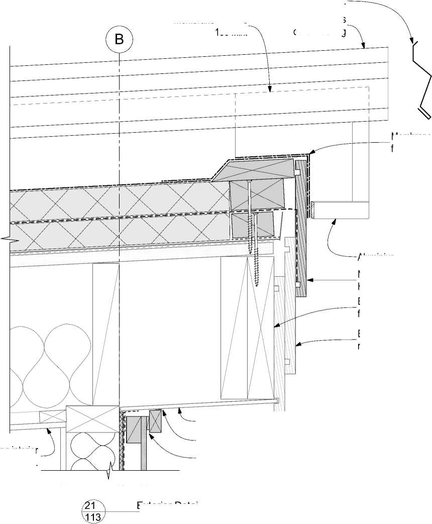
Membrane upstand 150 Min. |
|
Ventilation Gap: 3 - 5mm. Existing interior gs (Indicative). Membrane saddle flashing Aluminium pressure bar Existing fibre cement soffit retained. Continuous sealant bead. Exterior Detail 1:5 |
Membrane supplier's cover flashing
|
Existing wall finish. |
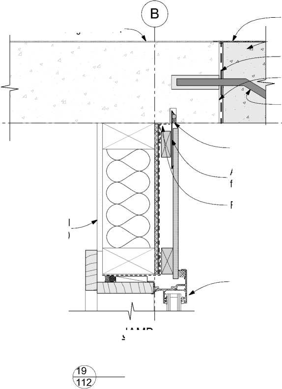 |
|
Flashing tape. JAMB Existing Internal linings (Indicative) 1:5 |
The contractor shall confirm all conditions and dimensions on site before proceeding with work. Do not scale dimensions off drawings. Contractor is to report any discrepancies to the architect immediately. Plans to be read in conjunction with the specification. RIA accepts no responsibility for any changes made to the issued documents.
|
DPC Concrete bonding agent. Existing concrete wall. Existing wall finish. Existing fascia board retained if suitable C.O.S. Window installation refer Detail 20. New concrete infill to raise sill height. New finish to infill concrete to match existing adjacent finish. Scabble surface of existing window opening. Continous sealant bead on PEF rod all-around opening. DPC | ||
|
Aluminium powder coated flashing, BMT 0.9 Min. | 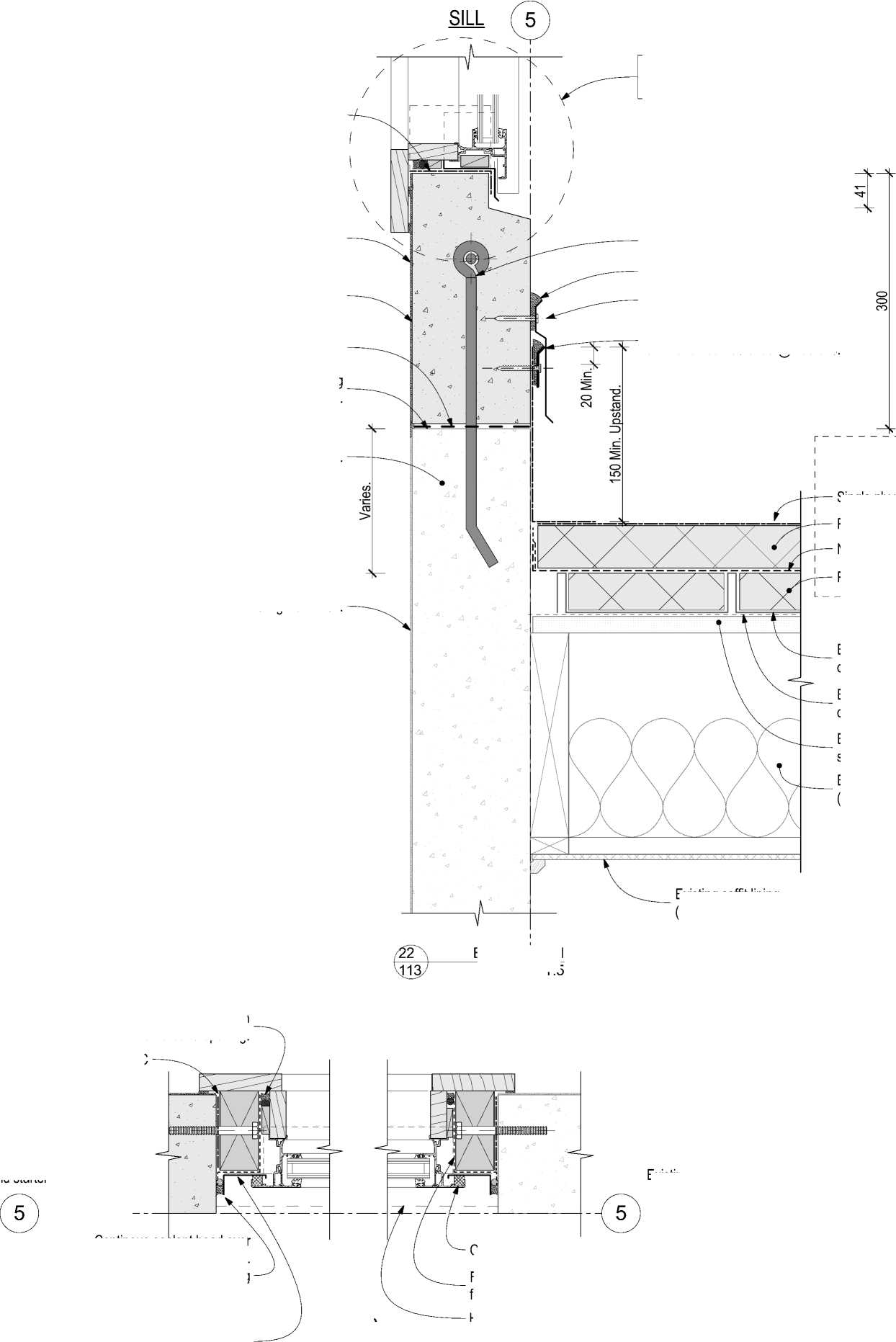 |
Single ply membrane PIR board (tapered). New vapour barrier |
|
PIR infill fillet. HEAD Existing concrete wall. DPC. Timber opening, H3.1. JAMB Existing soffit lining (Indicative). Compressible foam seal. Flashing tape all-around and full depth of opening. Head flashing above (dashed). Aluminium joinery (indicative). Timber reveal H3.1. | ||
Reinforcement and starter bars by Str. Eng.
Continuous sealant bead. Membrane manufacturers proprietory cover flashing.
Membrane manufacturers termination bar fastened @ 200 ctrs.
New fascia board, H3.2, Paint finished.
Existing timber framing (Indicative).
Existing tray profile roof cladding to remain.
Existing original membrane containing asbestos.
Existing original roof substrate (Indicative).
Existing roof structure (Indicative).
Exterior Detail
1:5
New finish to infill concrete to match existing adjacent finish.
— New concrete infill.
Concrete bonding agent.
Scabble surface of existing window opening.
Reinforcement and starter bars by Str. Eng.
Sealant bead.
Jamb detail "Typical".
Continous sealant bead over PEF backing rod. Grind smooth and clean existing concrete to accept both flashing tape and sealant.
Powdercoated aluminium Jamb flashing, BMT 0.9 Min.
Water resistant air seal on PEF backing rod.
20
Exterior Detail
1:5
|
Single ply membrane Membrane manufacturers termination bar shown hidden. Membrane manufacturers cover flashing. | ||
|
Trim existing metal roofing to this line. Existing concrete wall beyond. Membrane to be wrapped aroung external corner 100mm. Folded aluminium flashing BMT 2.0 Min. | 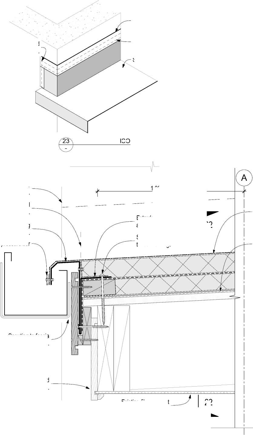
ISO 22 |
Existing retained metal roof cladding over original membrane (containing asbestos) and substrate. New overlay roof system installed over existing metal tray clad roof. |
|
Existing fascia board retained if suitable C.O.S. Existing fibre cement soffit retained. Spouting to fascia Gap 6 Min. 23 Exterior Detail 1:5 | ||
| |||||||||||||||||||||||||||||||||||||||||||||
|
Copyright RESOLVEiTARCHITECTS 2022© |
1,000 REF N.T.S.
Extruded aluminium angle cleat Ex. 75x50x3.
22
Aluminium pressure bar
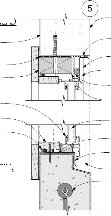 |
High build exterior paint finish. Sill tray upstand beyond. Flashing tape over Powdercoated aluminium flashing BMT 0.9 Min. to be sealed and riveted in place. Continous sealant bead over PEF backing rod. Grind smooth and clean existing concrete to accept both flashing tape and sealant. Jamb flashing beyond. Reinforcement and starter bars by Str. Eng. Compressible foam strip or sealant bead. Flashing tape over new timber packer and existing concrete. Roof membrane upstand dressed into opening. Sill Tray with corner saddles. Refer to isomeetric view. |
|
SILL | |
Screw fix to solid timber framing.
RESOLVE';
ARCHITECTS
LEVEL 1, 171 VIVIAN STREET, TE ARO
PO BOX 9792, WELLINGTON
RESOLVEiTARCHITECTS.CO.NZ
Client:
Naenae College
Project Name: Project Number: R21112
Naenae College
Administration Exterior
Project Address:
910 High Street Avalon Hutt City
|
Status: WRP Review & ProcurDate:t 15/08/2022 Scale: 1:5, 1:10 Size: A2 | ||||
|
CAD File: S:\Projects\R21112 - Naenae College Roof Remediation\A-Cad\R21112 Naenae College Admin Block-Developed Design 220727.pln
|
New pressure bar closer. Existing framing. Diverter cricket by overlay roof system manufacturer. Skylight installation Refer to Detail 15. New fascia board, H3.2, Paint finished. Existing fascia boards retained if suitable C.O.S. Existing timber framing (Indicative). Existing Internal linings (Indicative) | ||
|
SILL Existing sill location. Interior lining and finish. Refer to "Interiors" specification Air seal: Continuous sealant bead on PEF rod Note: Remove temporary packing from head. New framing to raise window sill in existing opening. Lintel: Existing (Indicative). Architrave. Refer to "Interiors" specification | 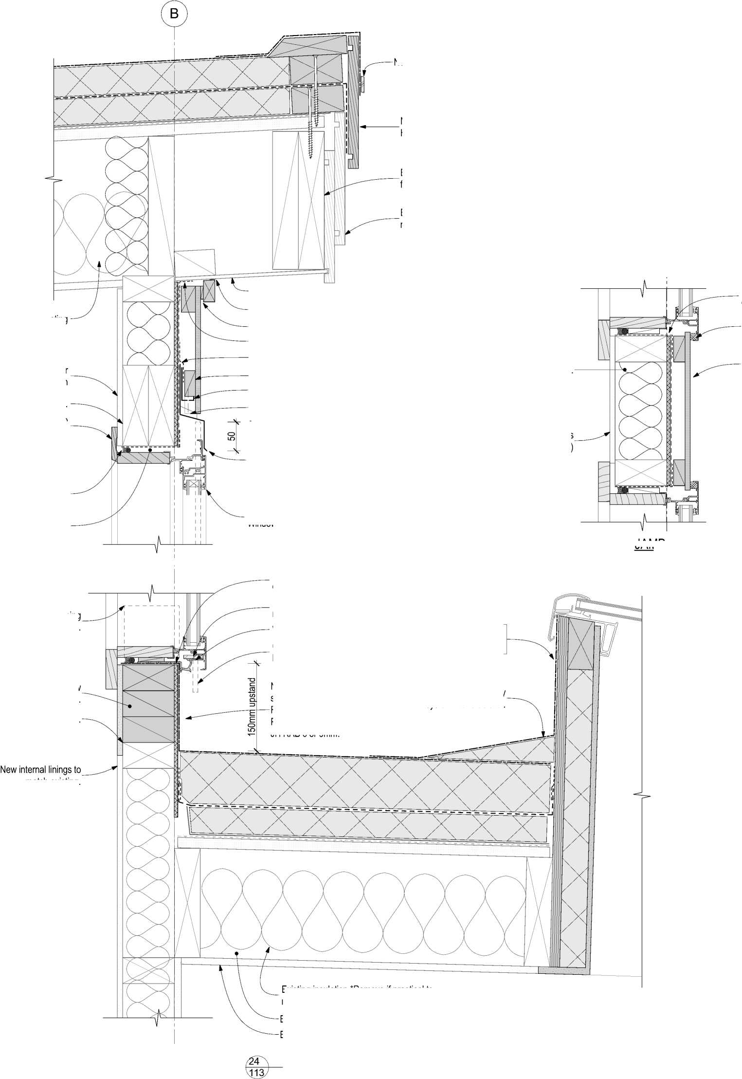
JAMB |
Exterior wall cladding, fibre cement sheet. Flashing tape dressed into opening (all around). Compressible foam seal. |
|
match existing. Existing insulation *Remove if practical to remove, Refer to Keynote 4711P on Sheet 001. Existing roof framing (Indicative). Existing ceiling lining. (Indicative) 1:5 | ||
Roof structure: Existing
Membrane dressed framing 100 Min.
Existing fibre cement soffit retained.
Continuous sealant bead.
Ventilation Gap: 3 - 5mm.
Flashing tape to junction of new RWU and existing soffit.
Flashing tape over head flashing and cavity
Cavity batten blocking 100mm @ 5°, H3.1. uPVC cavity closer
Cacity batten at sheet joints.
Powdercoated aluminium head
flashing BMT 0.9 Min. with stpoends, extend 20 Min. beyond joinery.
•
•
•
•
Cover to joinery 10 Min.
Gap to cladding 5 Min.
Slope 15° Min.
Cover to cladding 35 Min.
New aluminium joinery refer to Window and Door Schedule.
Flashing tape dressed into opening (all around).
Frame block by window manufacturer
WANZ sill support bar.
Cladding beyond shown hidden.
New upstand substrate over solid blocking.
RL Roof Board LW 10mm.
Plywood 12mm, H3.2 CCA.
JH RAB 6 or 9mm.
The contractor shall confirm all conditions and dimensions on site before proceeding with work. Do not scale dimensions off drawings. Contractor is to report any discrepancies to the architect immediately. Plans to be read in conjunction with the specification. RIA accepts no responsibility for any changes made to the issued documents.
| |||||||||||||||||||||||||||||||||||||||||||||
|
Copyright RESOLVEiTARCHITECTS 2022© |
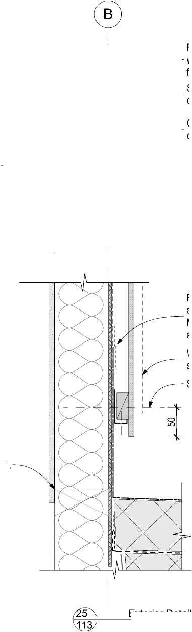 |
Sill height of adjacent window. Continuous head flashing over all clerestory windows. Flashing tape over waterproof membrane, head flashing and cavity closer. Stopend to end windows only. |
|
Exterior Detail 1:5 | |
|
Existing structure (Indicative). | 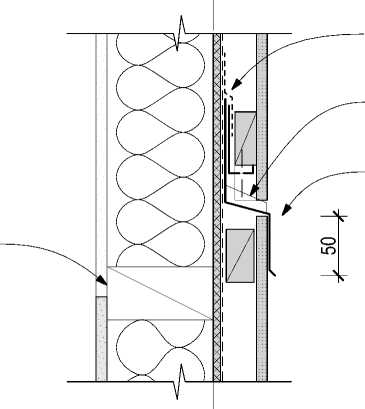 |
Flashing tape over vapour and waterproof membrane. Membrane height 100 Min. above adjacent sill height.
Window joinery beyond shown hidden.
Existing sill location.
RESOLVE';
ARCHITECTS
LEVEL 1, 171 VIVIAN STREET, TE ARO
PO BOX 9792, WELLINGTON
RESOLVEiTARCHITECTS.CO.NZ
Client:
Naenae College
Project Name: Project Number: R21112
Naenae College
Administration Exterior
Project Address:
910 High Street Avalon Hutt City
|
Status: WRP Review & ProcurDate:t 15/08/2022 Scale: 1:5 Size: A2 | ||||
|
CAD File: S:\Projects\R21112 - Naenae College Roof Remediation\A-Cad\R21112 Naenae College Admin Block-Developed Design 220727.pln
New overlay roof system installed over existing metal tray clad roof.
|
Aluminium pressure bar. Trim existing metal roofing to this line. Screw fix to solid timber framing. Bottom of sheet parallel to roof below. Height to roof 150 Min. New fibre cement sheet fascia board. Paint finish. Extruded aluminium angle cleat Ex. 75x50x3. Single ply membrane over plywood substrate 17 Min. H3.2 CCA. New waterproof membrane/PIR roof system installed over new plywood substrate. Aligns with overlay roof system beyond. New roof structure and trusses. Refer to Str. Eng. | ||
|
Existing insulation *Remove if practical to remove, Refer to Keynote 4711P on Sheet 001. Existing interior lining. Finish: Refer interior project specification. Existing ceiling lining(Indicative). Existing roof structure (Indicative). | 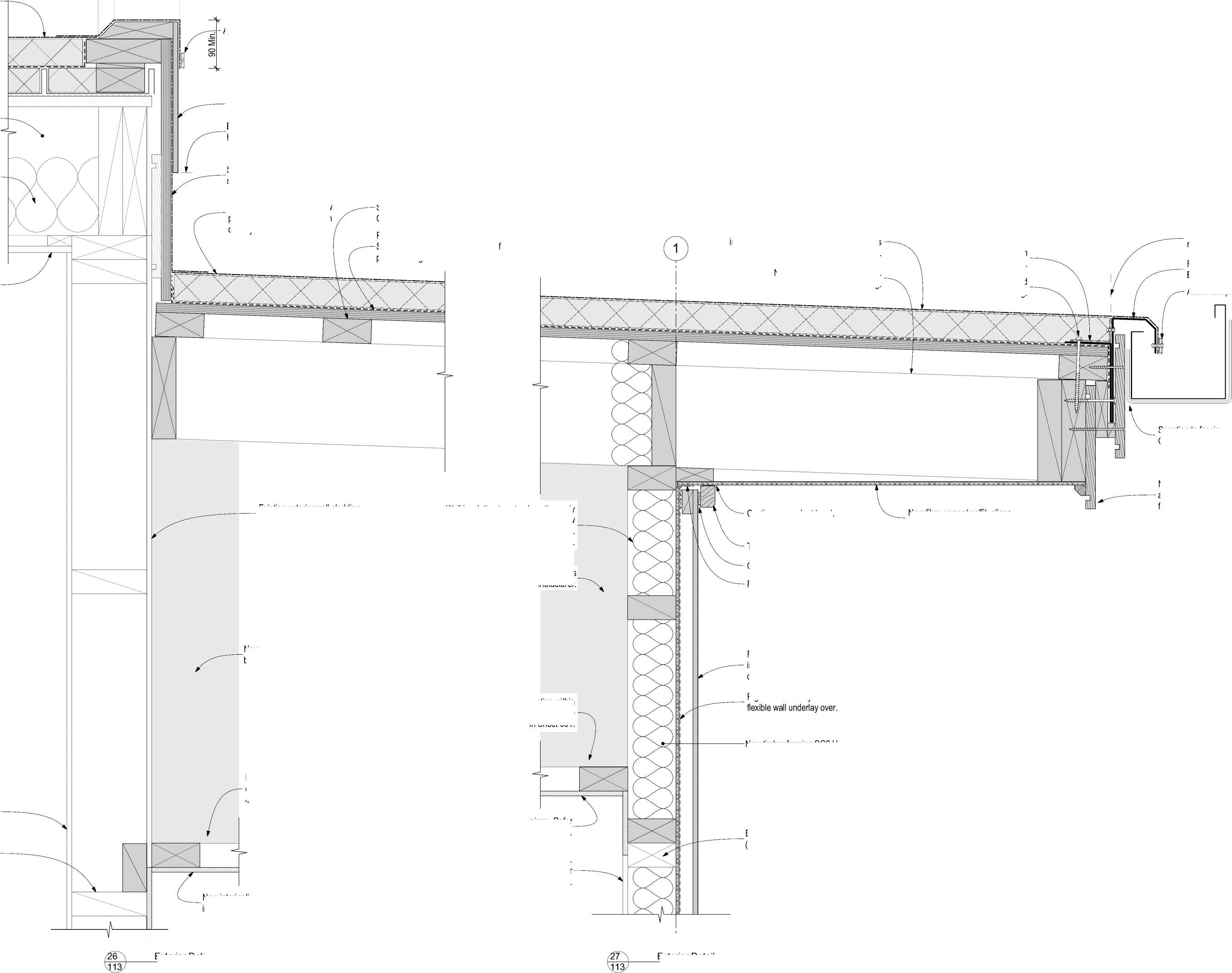 |
Timber eaves mould 40x27, H3.1. Paint finish. Cavity ventilation gap 3 - 5mm. Flashing tape Soffit/RWU junction. New fascia board, size and alignment as per existing fascia board beyond. Fibre cement panel wall cladding installed vertically over H3.1 timber cavity battens. Paint finish. Folded aluminium flashing BMT 2.0 Min. LEVEL 1, 171 VIVIAN STREET, TE ARO PO BOX 9792, WELLINGTON RESOLVEiTARCHITECTS.CO.NZ Project Name: Project Number: R21112 Naenae College Administration Exterior Project Address: 910 High Street Avalon Hutt City |
|
New timber framing SG8 H1.2. Scale: 1:5 New interior linings. Refer interior project specification. New interior linings. Refer interior project specification. Existing interior lining. Finish: Refer interior project specification. New fibre cement soffit, aligns with existing soffit beyond. New truss/roof structure by Str. Eng. TBC. Spouting to fascia Gap 6 Min. Existing exterior wall cladding, various (Indicative). Existing wall framing (Indicative) Do not install insulation within ceiling void. Refer to Keynote 4711P on Sheet 001. Exterior Detail 1:5 Exterior Detail 1:5 | ||
New waterproof membrane/PIR roof system installed over new plywood substrate. Aligns with overlay roof system beyond.
Purlins to tie top chord of trusses, SG8, H1.2.
Centres and fixings to be confirmed.
Plywood subtrate 17 Min. H3. CCA. Str. Eng. to confirm if utilised as roof plane bracing.
Wall insulation to extend continuously up to the underside of the new insulated overlay roof system. Typical. Refer to Keynote 4711P on Sheet 001.
Continuous sealant bead.
New roof truss by Truss Manufacturer.
Do not install insulation within ceiling void. Refer to Keynote 4711P on Sheet 001.
Rigid wall underlay with
The contractor shall confirm all conditions and dimensions on site before proceeding with work. Do not scale dimensions off drawings. Contractor is to report any discrepancies to the architect immediately. Plans to be read in conjunction with the specification. RIA accepts no responsibility for any changes made to the issued documents.
| |||||||||||||||||||||||||||||||||||||||||||||
|
Copyright RESOLVEiTARCHITECTS 2022© |
Aluminium pressure bar
RESOLVE';
ARCHITECTS
Client:
Naenae College
|
Status: WRP Review & ProcurDate:t 15/08/2022 Size: A2 | ||||
|
CAD File: S:\Projects\R21112 - Naenae College Roof Remediation\A-Cad\R21112 Naenae College Admin Block-Developed Design 220727.pln
The contractor shall confirm all conditions and dimensions on site before proceeding with work. Do not scale dimensions off drawings. Contractor is to report any discrepancies to the architect immediately. Plans to be read in conjunction with the specification. RIA accepts no responsibility for any changes made to the issued documents.
|
Copyright RESOLVEiTARCHITECTS 2022© New timber decking, H3.2, smooth side up. Plywood subtrate 17 Min. H3.2 CCA. Floor within building beyond shown dashed. Waterproof membrane over PIR board over vapor barrier and plywood substrate. Steel ridge beam. Refer Structural Engineer's documentation. Timber screen/balustrade. Roof Framing Rafters: 190x45 SG8 Min. @ 600 Ctrs Max. Fixings: Type E, 2/90x3.15 skew nails plus 2 wire dogs. NZS 3604 Table 10.1 Centred about new Administration Entrance. Align with Centreline of handrail Slope Posts and Palings 5 |
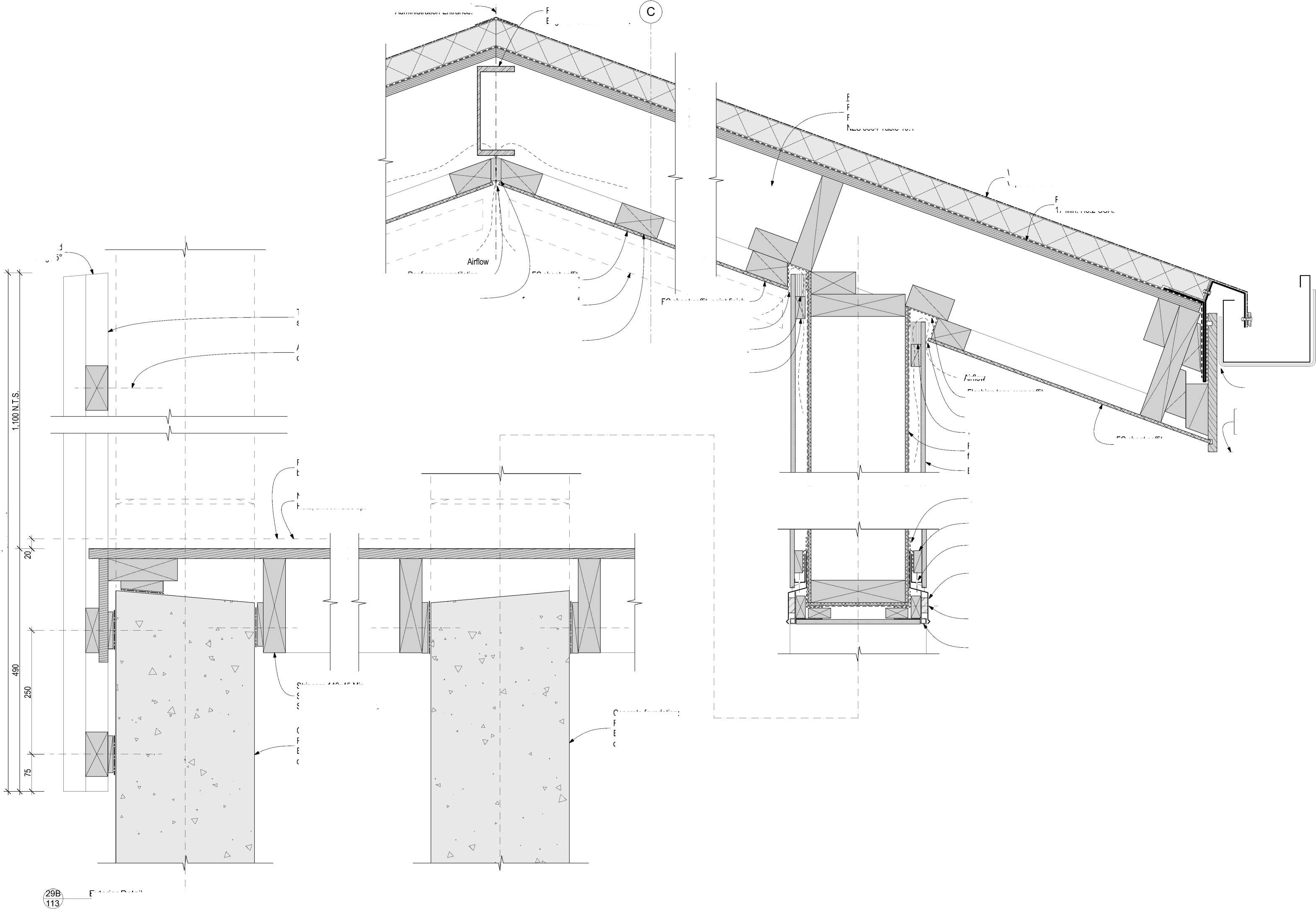
Airflow |
|
uPVC cavity closer Status: WRP Review & ProcurDate:t 15/08/2022 Scale: 1:5 Size: A2 FC sheet soffit, paint finish. Concrete foundation: Refer Structural Engineer's documentation. Concrete foundation: Refer Structural Engineer's documentation. Head flashing as per window head flashing. Powdeer coated aluminium, BMT 0.9 Min. Powdercaoted aluminium external boxed corner extrusion. Spouting to fascia Gap 6 Min. Fix head flashing through EPDM packer. Align with adjacent fascia of main building. Stringers 140x45 Min. SG8, H3.2, Bolts M12 S.S. at 0.7m centres Max. LEVEL 1, 171 VIVIAN STREET, TE ARO PO BOX 9792, WELLINGTON RESOLVEiTARCHITECTS.CO.NZ Flashing tape over both flashing and cavity closer. Cavity batten blocking 100mm @ 5°, H3.1. flexible wall underlay over. Exterior wall cladding. Flashing tape over soffit and wall underlay. Top of cavity ventilation Gap 5mm. Vent batten. Project Name: Project Number: R21112 Naenae College Administration Exterior Project Address: 910 High Street Avalon Hutt City 1:5 |
|
Rev. |
Description |
Date |
|
P-05 |
Detail Design-04 |
27/07/2022 |
|
A |
WRP Review & Procurement Issue |
15/08/2022 |
Roof space ventilation Gap 8mm.
Vent batten.
FC sheet soffit, paint finish.
Future suspended artwork / panelling.
FC sheet soffit, paint finish.
1,590 N.T.S.
Soffit Battens: 90x45 H1.2 @ 600 ctrs Fixing Type "U" (1/14g x 100mm self-drilling type 17 screw). Note: Over sized to provide fixing of future decorative features to solid timber framing.
**Provide locations for fixing future decorative features to front face and interior walls. Photograph and as-build framing prior to installing the RAB and deliver to contract administrator.
Cavity ventilation Gap 5mm.
Vent batten.
Timber blocking at sheet fixing locations or
castellated cavity
batten.
RESOLVE1;
ARCHITECTS
Client:
Naenae College
|
Drawing No. |
Revision No. |
|
511 |
A |
CAD File: S:\Projects\R21112 - Naenae College Roof Remediation\A-Cad\R21112 Naenae College Admin Block-Developed Design 220727.pln
|
New overlay roof system installed over new plywood. roof substrate. New overlay roof system installed over new plywood roof substrate. | |
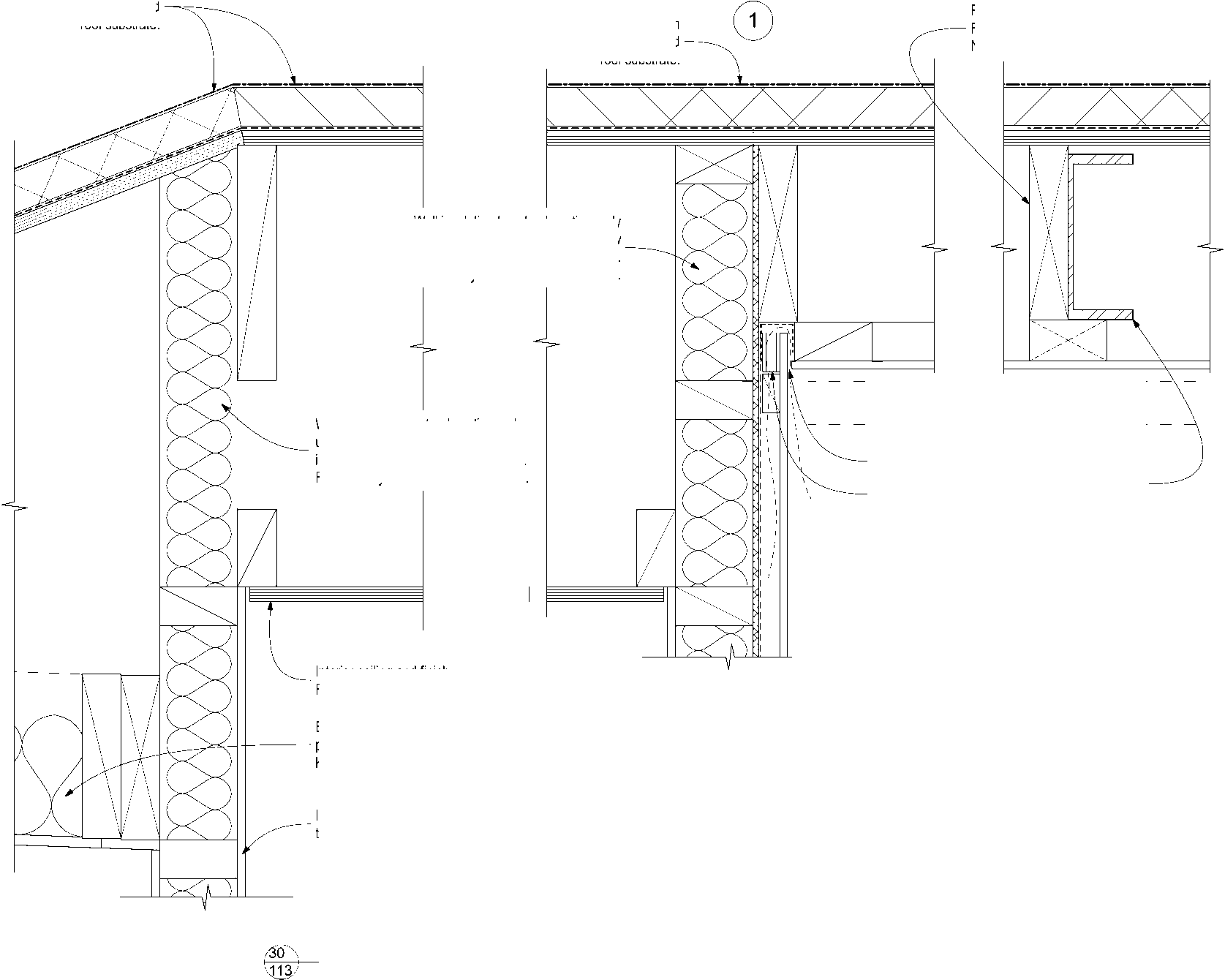 |
Rafters: 190x45 SG8 Min. @ 600 Ctrs Max. Fixings: Type E, 2/90x3.15 skew nails plus 2 wire dogs. NZS 3604 Table 10.1 |
|
Airflow Existing insulation *Remove if practical to remove, Refer to Keynote 4711P on Sheet 001. Interior lining and finish. Refer to "Interiors" specification Interior ceiling and finish. Refer to "Interiors" specification PFC beam of portal frame (Indicative), refer to Structural Engineer's documentation. Top of cavity ventilation Gap Vent batten. Aluminium pressure bar New Barge board, H3.2, Paint finished. 1:5 | |
Wall insulation to extend continuously up to the underside of the new insulated overlay roof system. Typical. Refer to Keynote 4711P on Sheet 001.
Wall insulation to extend continuously up to the underside of the new insulated overlay roof system. Typical. Refer to Keynote 4711P on Sheet 001.
w overlay roof system installed over new
lywood
roof substrate.
Soffit Battens: 90x45 H1.2 @ 600 ctrs Fixing Type "U" (1/14g x 100mm selfdrilling type 17 screw).
Note: Over sized to provide fixing of future decorative features to solid timber framing.
|
Aluminium pressu Future decorative New fascia board Paint finish. | |
|
Single ply membrane Soffit lining. shown dashed. Overlay roof system New entrance canopy roof structure (Indicative). PIR board. Plywood roof substrate 17mm H3.2 CCA. | 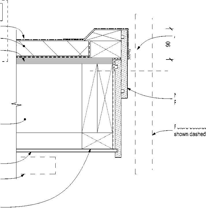 |
The contractor shall confirm all conditions and dimensions on site before proceeding with work. Do not scale dimensions off drawings. Contractor is to report any discrepancies to the architect immediately. Plans to be read in conjunction with the specification. RIA accepts no responsibility for any changes made to the issued documents.
| |||||||||||||||||||||||||||||||||||||||||||||
|
Copyright RESOLVEiTARCHITECTS 2022© |
**Provide locations for fixing future decorative features to front face and interior walls. Photograph and as-build framing prior to installing the RAB and deliver to contract administrator.
|
2,300 NTS New overlay roof system installed over existing metal tray clad roof. New overlay roof cladding over new roof structure. | |
|
Cavity ventilation Gap 3 - 5 mm. Flashing tape to timber top plate and wall underlay. New timber framing SG8 H1.2. Rigid wall underlay with flexible wall underlay over. Exterior wall cladding. | 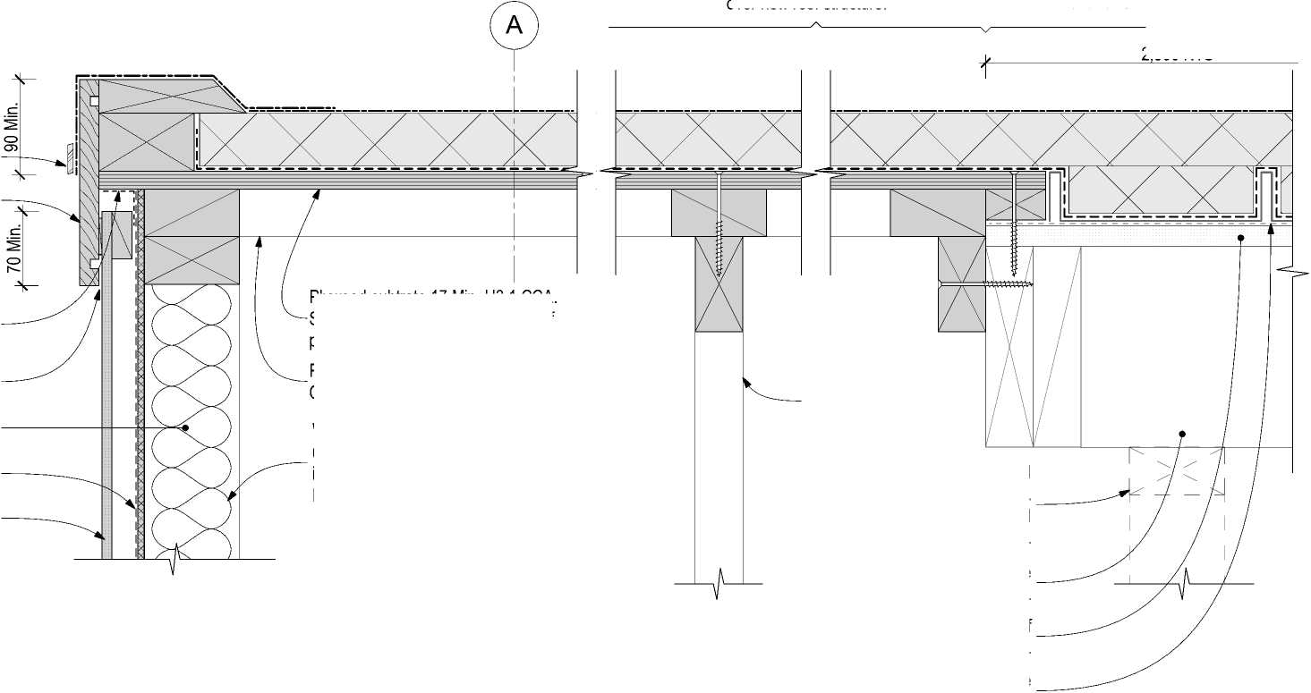 |
|
Existing wall removed Str. Eng. to confirm load bearing prior to removal. New timber trusses (Indicative). Design by truss manufacturer. Wall insulation to extend continuously up to the underside of the new insulated overlay roof system. Typical. Refer to Keynote 4711P on Sheet 001. Purlins to tie top chord of trusses, SG8, H1 Centres and fixings to be confirmed. Existingroof sturcutre remains (Indicative). Existing original roof substrate (Indicative). Existing original membrane containing asbestos. | |
Plywood subtrate 17 Min. H3.1 CCA. Str. Eng. to confirm if utilised as roof plane bracing.
28
Exterior Detail
1:5
 |
|
New ceiling lining on purlins (Indicative). |
Do not install insulation within ceiling void. Refer to Keynote 4711P on Sheet 001.

RESOLVE';
ARCHITECTS
LEVEL 1, 171 VIVIAN STREET, TE ARO
PO BOX 9792, WELLINGTON
RESOLVEiTARCHITECTS.CO.NZ
Client:
Naenae College
Project Name: Project Number: R21112
Naenae College
Administration Exterior
Project Address:
910 High Street Avalon Hutt City
|
Status: WRP Review & ProcurDate:t 15/08/2022 Scale: 1:5 Size: A2 | ||||
|
CAD File: S:\Projects\R21112 - Naenae College Roof Remediation\A-Cad\R21112 Naenae College Admin Block-Developed Design 220727.pln
A
Detail 29
The contractor shall confirm all conditions and dimensions on site before proceeding with work. Do not scale dimensions off drawings. Contractor is to report any discrepancies to the architect immediately. Plans to be read in conjunction with the specification. RIA accepts no responsibility for any changes made to the issued documents.
|
280 Flashing tape over cavity closer. New timber decking, H3.2, smooth side up. Cavity batten blocking 100mm @ 5°, H3.1. Wall finish. Refer to interior project. Steel Portal Frame, refer Structural Engineer's documentation. Floor within building beyond shown dashed. Fibre cement panel wall cladding installed vertically over H3.1 timber cavity battens. Paint finish. Extend 50mm below floor framing. Rigid wall underal with wall underlay over. Extend 15mm below floor framing. uPVC cavity closer Cacity batten at sheet joints. |
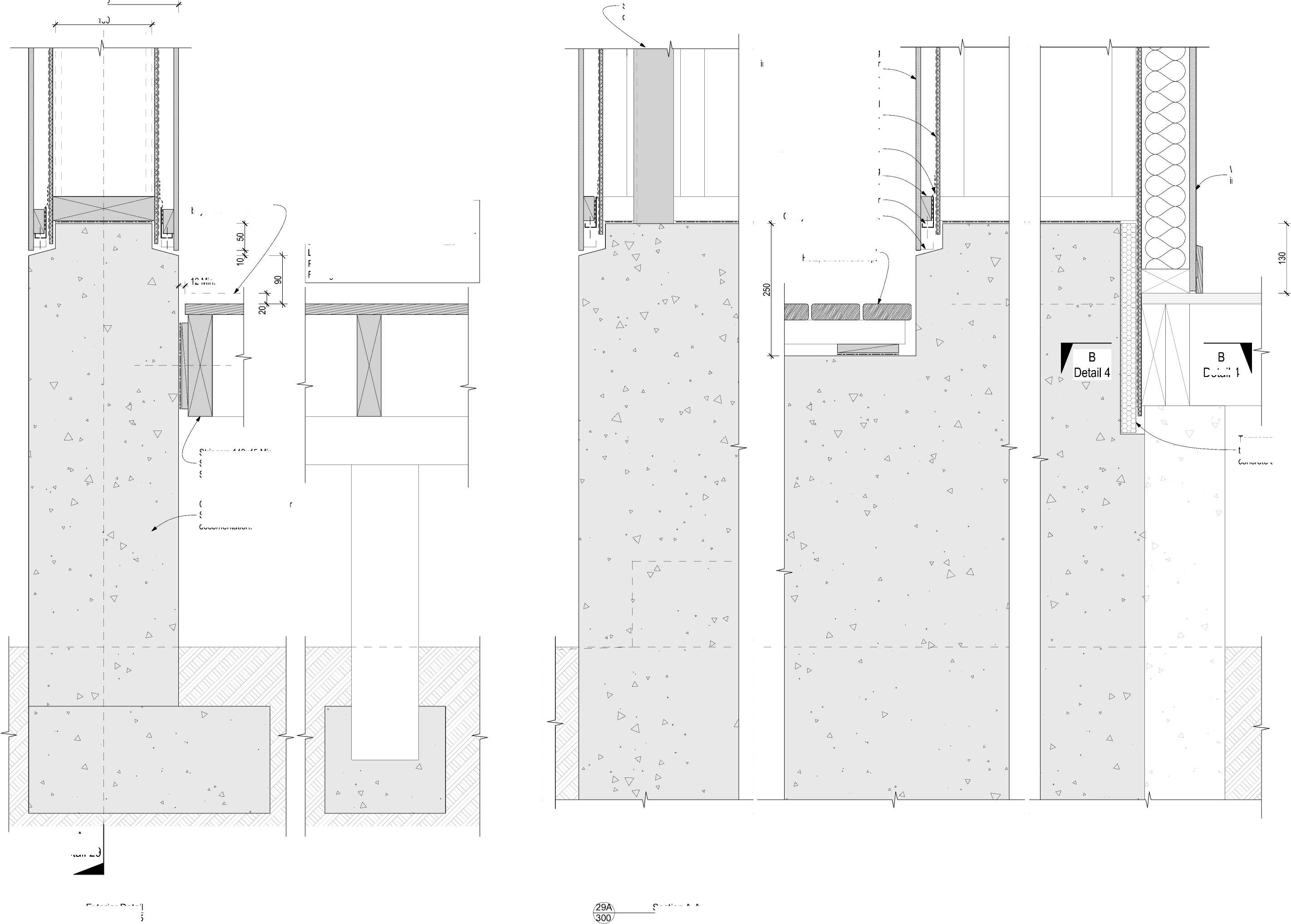
180 12 Min. Detail 4 |
|
9A Exterior Detail 1:5 Section A-A 1:5 |
Deck Design (NZS 3604 3kPa Floor Loading)
Decking: 88 x32 H3.2
Joist: 140x45 Min. SG8 H3.2, (Span 2.15m Max).
Bearer: 90x90 SG8 H3.2, Span 1,300 Max.
Loaded dimension 1,000 Max. Pile: 125x125 H5
Footing Concrete: 225x225x200 Min
A
Detail 29
Stringers 140x45 Min.
SG8, H3.2, Bolts M12
S.S. at 0.7m centres Max.
Concrete foundation: Refer Structural Engineer's documentation.
| |||||||||||||||||||||||||||||||||||||||||||||
|
Copyright RESOLVEiTARCHITECTS 2022© |
Temporary EPS formwork, to be removed post concrete cure.
RESOLVE';
ARCHITECTS
LEVEL 1, 171 VIVIAN STREET, TE ARO
PO BOX 9792, WELLINGTON
RESOLVEiTARCHITECTS.CO.NZ
Client:
Naenae College
Project Name: Project Number: R21112
Naenae College
Administration Exterior
Project Address:
910 High Street Avalon Hutt City
|
Status: WRP Review & ProcurDate:t 15/08/2022 Scale: 1:5 Size: A2 | ||||
|
CAD File: S:\Projects\R21112 - Naenae College Roof Remediation\A-Cad\R21112 Naenae College Admin Block-Developed Design 220727.pln

|
New overlay roof system installed over existing metal tray clad roof. Screw fix to solid timber framing. Trim existing metal roofing to this line. Extruded aluminium angle cleat Ex. 75x50x3. Existing retained metal roof cladding over original membrane (containing asbestos) and substrate. | ||
|
Existing Internal linings (Indicative) Wall finish. Refer to interior project. Existing framing (Indicative) Wall insulation to extend continuously up to the underside of the new insulated overlay roof system. Typical. Refer to Keynote 4711P on Sheet 001. Do not install insulation within ceiling void. Refer to Keynote 4711P on Sheet 001. New floor finish. Refer to interior project. (Indicative). Existing timber floor (Indicative). | 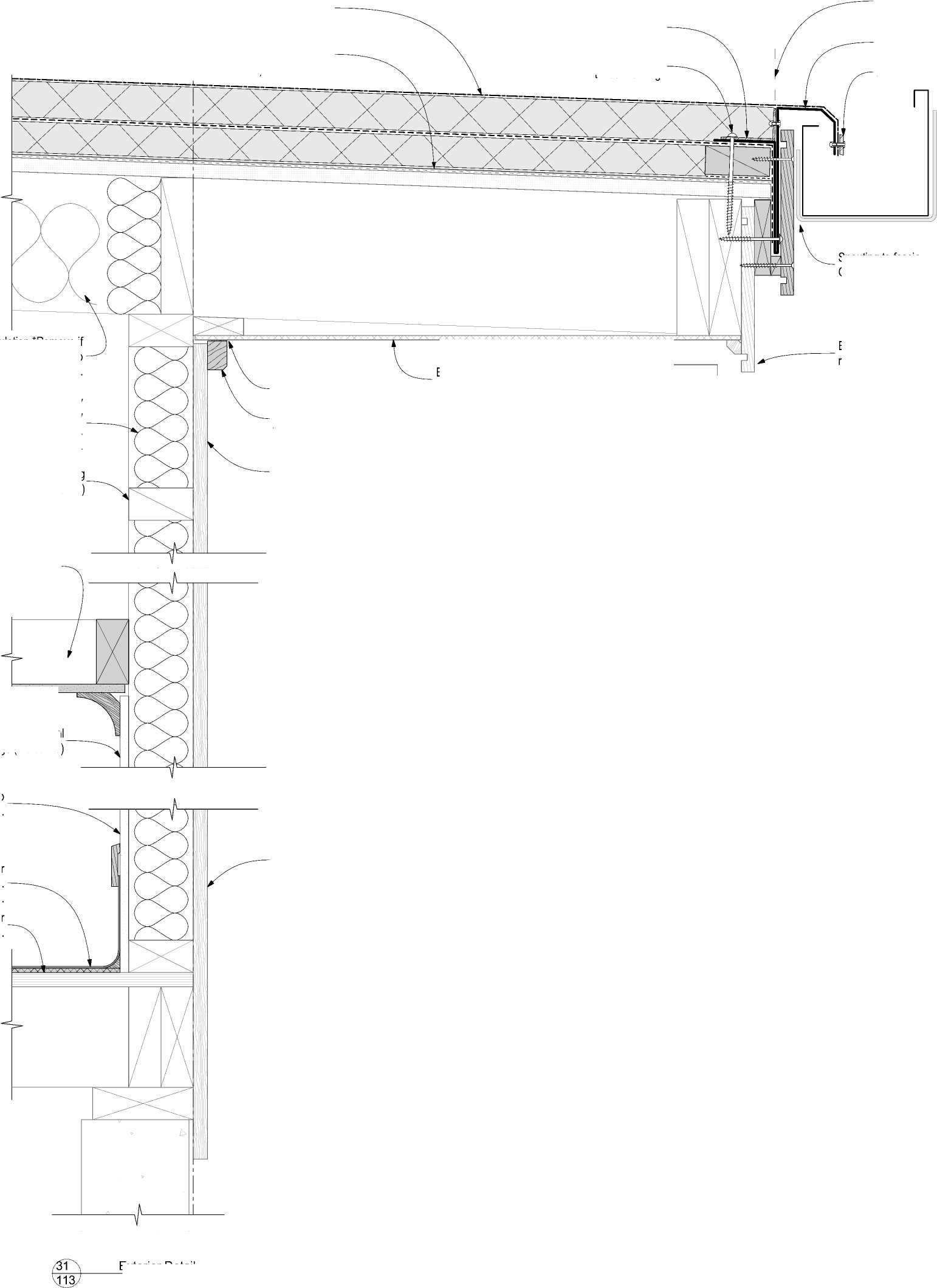 |
Aluminium pressure bar Folded aluminium flashing BMT 2.0 Min. New plywood substrate to existing skylight opening as required. |
|
Continuous sealant bead. Existing direct fixed vertical shiplap weatherboards. Make good and paint finish. Existing direct fixed vertical shiplap weatherboards. Make good and paint finish. Timber eaves mould 40x27, H3.1. Paint finish. Existing fascia board retained if suitable C.O.S. Existing fibre cement soffit retained. Spouting to fascia Gap 6 Min. Pipe penetration Modified silicion sealant all around. New timber framing H1.2 to existing skylight opening as required. Secure pipe with suitable brackets and pipe clamp. CAUTION Assume all exisitng fibre cement sheet to contain asbestos unless confirmed otherwise. 32 1:5 Exterior Detail 1:5 | ||
Existing insulation *Remove if practical to remove, Refer to Keynote 4711P on Sheet 001.
|
Pressure sealing tape S.S. worm drive clamp. Flashing tape to seal vapour barrier. Roof membrame system detail piece. Proprietory natural lighting tube. Proprietory flashing and adapter for natural lighting tube. Timber framed opening to natural light tube manufacturers specification. Upstand 150 Min. Roof membrane system collar fully welded by approved installer.. |
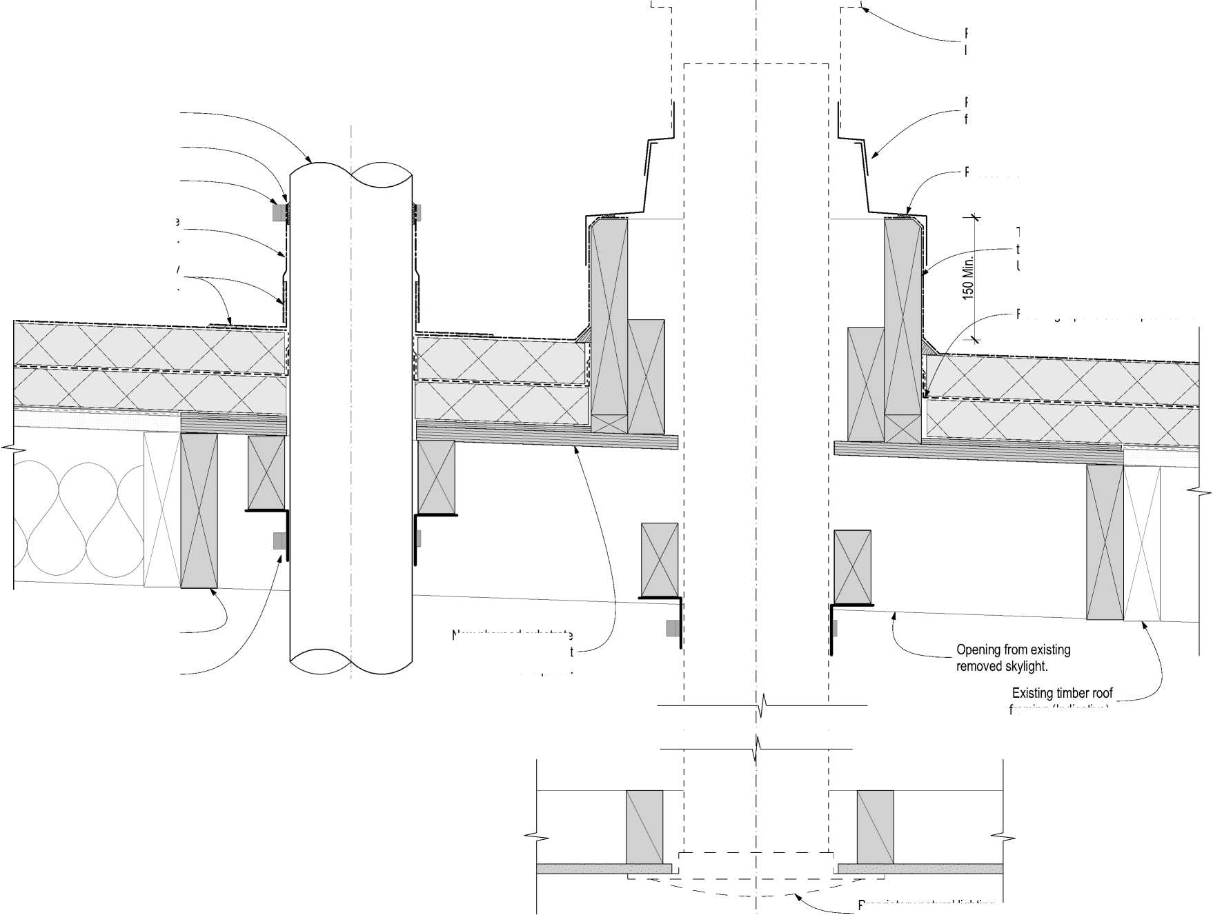 |
|
Pipe Penetration framing (Indicative). Proprietory natural lighting tube ceiling diffuser. |
Natural Light Tube
The contractor shall confirm all conditions and dimensions on site before proceeding with work. Do not scale dimensions off drawings. Contractor is to report any discrepancies to the architect immediately. Plans to be read in conjunction with the specification. RIA accepts no responsibility for any changes made to the issued documents.
| |||||||||||||||||||||||||||||||||||||||||||||
|
Copyright RESOLVEiTARCHITECTS 2022© |
RESOLVE'1
ARCHITECTS
LEVEL 1, 171 VIVIAN STREET, TE ARO
PO BOX 9792, WELLINGTON
RESOLVEiTARCHITECTS.CO.NZ
Client:
Naenae College
Project Name: Project Number: R21112
Naenae College
Administration Exterior
Project Address:
910 High Street Avalon Hutt City
|
Status: WRP Review & ProcurDate:t 15/08/2022 Scale: 1:5 Size: A2 | ||||
|
CAD File: S:\Projects\R21112 - Naenae College Roof Remediation\A-Cad\R21112 Naenae College Admin Block-Developed Design 220727.pln
New overlay roof system installed over existing metal tray clad roof.
The contractor shall confirm all conditions and dimensions on site before proceeding with work. Do not scale dimensions off drawings. Contractor is to report any discrepancies to the architect immediately. Plans to be read in conjunction with the specification. RIA accepts no responsibility for any changes made to the issued documents.
| |||||||||||||||||||||||||||||||||||||||||||||
|
Copyright RESOLVEiTARCHITECTS 2022© |
|
Existing Hall interior linings (Indicative). | ||
|
Membrane roof below. Membrane manufacturers proprietory diverter below. | 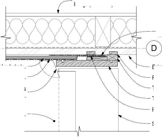 |
Rustic plug. Spouting below. Membrane internal back flashing taken up behind roof membane. |
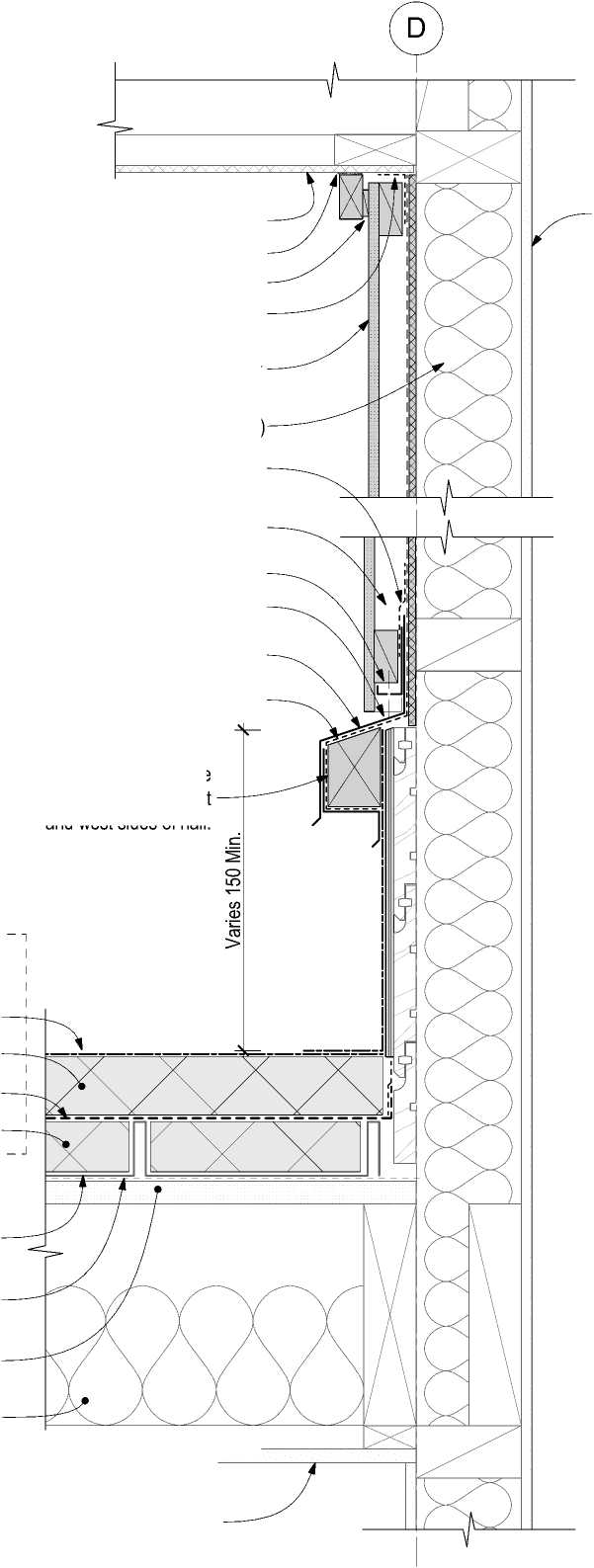 |
Existing Hall interior linings (Indicative). |
|
Existing Lobby interior linings (Indicative). | |
Existing fibre cement soffit retained. Continuous sealant bead.
Cavity ventilation gap 3 - 5mm. Flashing tape Soffit/RWU junction.
Fibre cement panel wall cladding installed vertically over H3.1 timber cavity battens. Paint finish.
Existing framing (Indicative) Flashing tape over both flashing and cavity closer.
Cavity batten blocking 100mm @ 5°, H3.1.
uPVC cavity closer Cacity batten at sheet joints. Aluminium Flashing BMT 1.2 Min. Powdercoated.
Flashing tape separation.
Timber batten H3.2. Profile to match existiing on east and west sides of hall.
Plywood substrate.
Waterproof membrane upstand.
Existing rusticated weatherboards.
Rustic plug, installed with sealant.
Timber packing H3.2.
Timber cover board 180x18 H3.2.
View C-C
Membrane internal back flashing taken up behind roof membane.


Single ply membrane PIR board (tapered).
New vapour barrier PIR infill fillet.
Existing tray profile roof cladding to remain.
Existing original membrane containing asbestos.
Existing original roof substrate (Indicative).
Existing roof structure (Indicative).
|
Membrane manufacturers proprietory diverter. Existing weatherboards remain in place. Membrane behind cover board shown hidden. |
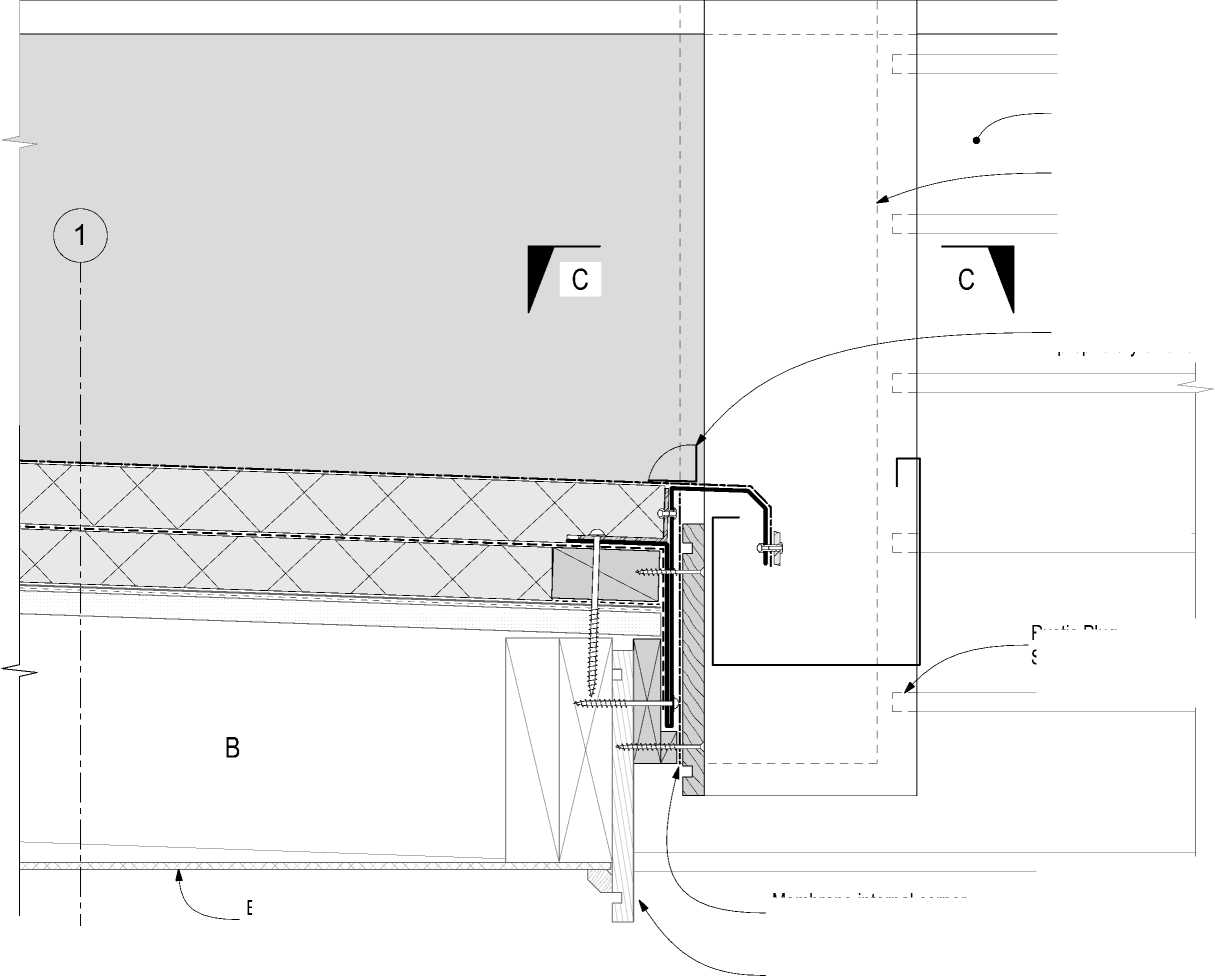 |
|
Existing fibre cement soffit retained. Membrane internal corner back flashing. Existing fascia board retained if suitable C O S |
RESOLVE';
ARCHITECTS
LEVEL 1, 171 VIVIAN STREET, TE ARO
PO BOX 9792, WELLINGTON
RESOLVEiTARCHITECTS.CO.NZ

Exterior Detail
1:5

Exterior Detail
1:5
Rustic Plug
Sealed to wbd. Typical.
Client:
Naenae College
Project Name: Project Number: R21112
Naenae College
Administration Exterior
Project Address:
910 High Street Avalon Hutt City
|
Status: WRP Review & ProcurDate:t 15/08/2022 Scale: 1:5 Size: A2 | ||||
|
CAD File: S:\Projects\R21112 - Naenae College Roof Remediation\A-Cad\R21112 Naenae College Admin Block-Developed Design 220727.pln
|
Rustic Plug, sealed to wbd. Aluminium pressure bar New fibre cement panel cladding on drained cavity to Hall gable. New horizontal cladding change band. Folded powder coated aluminium flashing, BMT 2.0 Min. Membrane saddle flashing. Membrane internal corner back flashing. New fascia board, H3.2, Paint finished. Membrane upstand behind cladding shown hidden. Membrane internal back flashing taken up behind roof membane. Existing timber framing (Indicative). Existing fascia board retained if suitable C.O.S. | 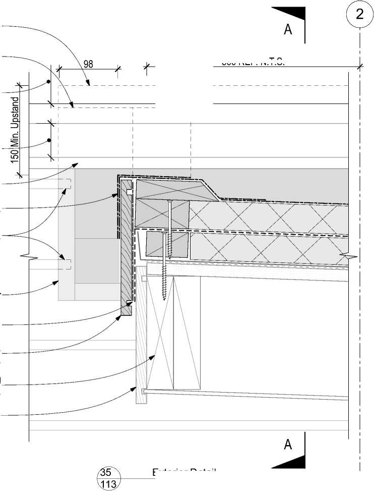
560 REF. N.T.S. |
|
Exterior Detail 1:5 | |
Existing weatherboards removed and replaced with new as required to facilitate membrane installation.
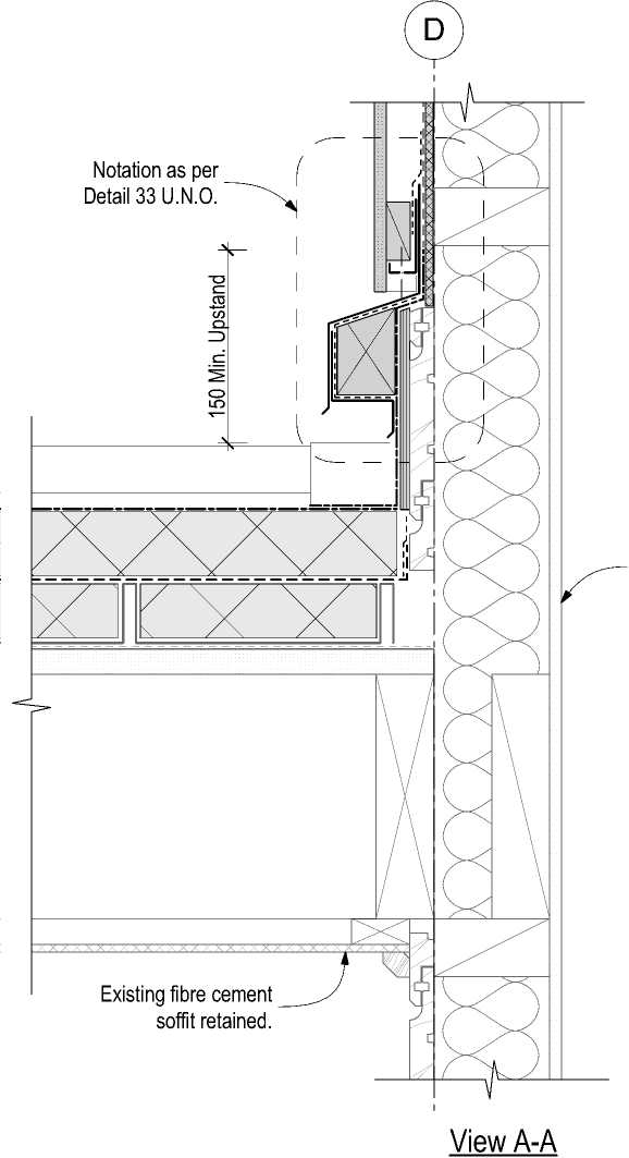 |
Existing Hall interior linings (Indicative). |

|
Existing framing (Indicative) Existing Fibre cement wall cladding (Indicative). Existing horizontal band | |
|
New corner saddle flashing, Prefinished steel flashing BMT 0.55 Min. folded and fully sealed. Refer isometric view. | 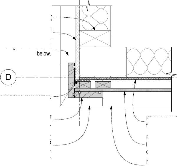
,u |
|
Flashing tape over corner. New timber external corner boards, H3.2, Paint finished. New horizontal band below. | |

Rigid wall underlay with flexible wall underlay over.
Fibre cement panel wall cladding installed vertically over H3.1 timber cavity battens. Paint finish.
Exterior Detail
1:5
The contractor shall confirm all conditions and dimensions on site before proceeding with work. Do not scale dimensions off drawings. Contractor is to report any discrepancies to the architect immediately. Plans to be read in conjunction with the specification. RIA accepts no responsibility for any changes made to the issued documents.
| |||||||||||||||||||||||||||||||||||||||||||||
|
Copyright RESOLVEiTARCHITECTS 2022© |
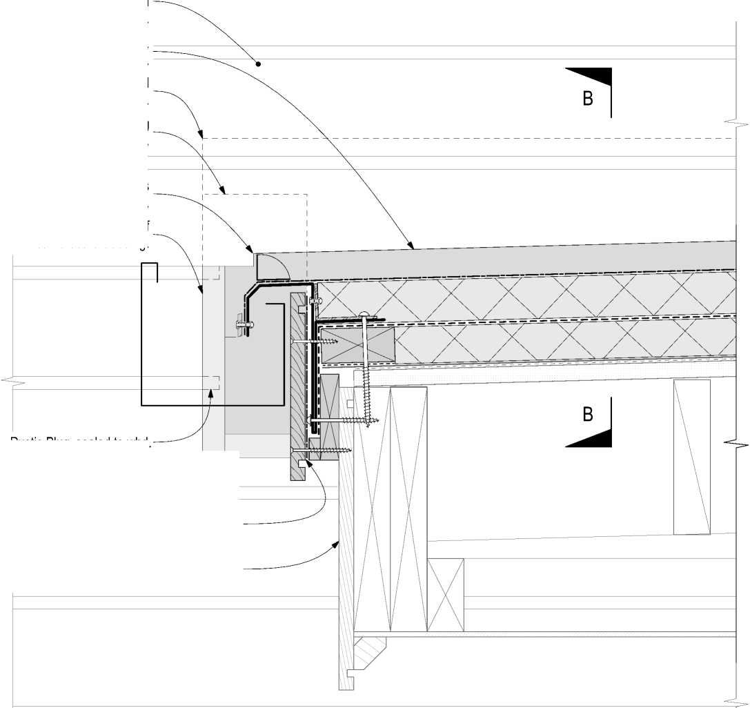
Rustic Plug, sealed to wbd.
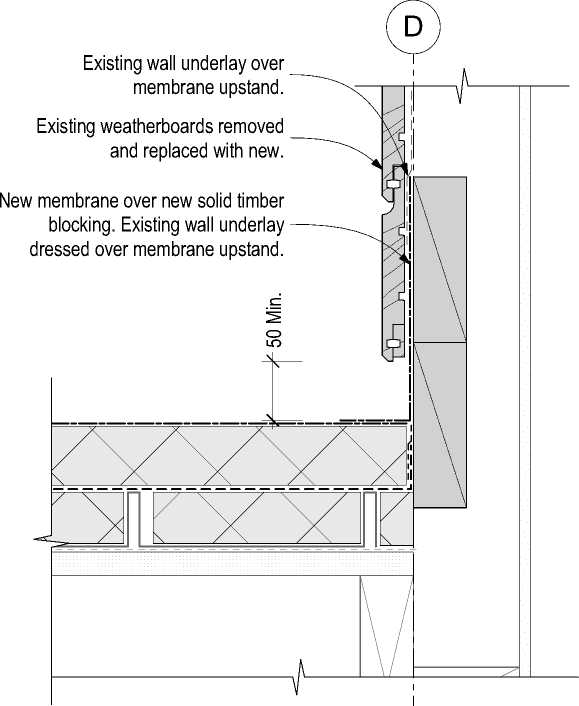
View B-B
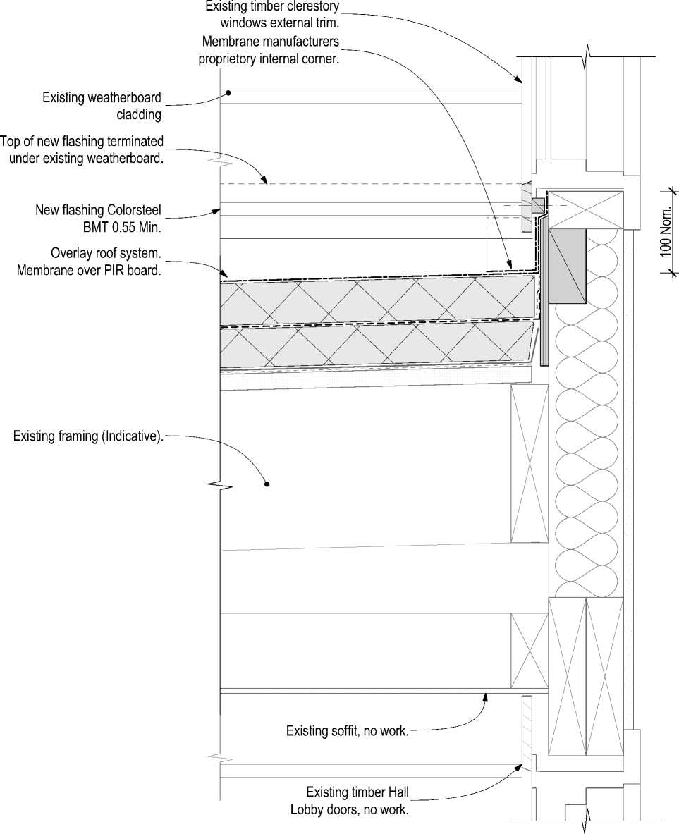
RESOLVE';
ARCHITECTS
LEVEL 1, 171 VIVIAN STREET, TE ARO PO BOX 9792, WELLINGTON
RESOLVEiTARCHITECTS.CO.NZ
Client:
Naenae College
Project Name: Project Number: R21112
Naenae College
Administration Exterior
Project Address:
910 High Street Avalon Hutt City

Exterior Detail
1:5

Exterior Detail
1:5
|
Status: WRP Review & ProcurDate:t 15/08/2022 Scale: 1:5 Size: A2 | ||||
|
CAD File: S:\Projects\R21112 - Naenae College Roof Remediation\A-Cad\R21112 Naenae College Admin Block-Developed Design 220727.pln
|
Existing Internal linings (Indicative) | 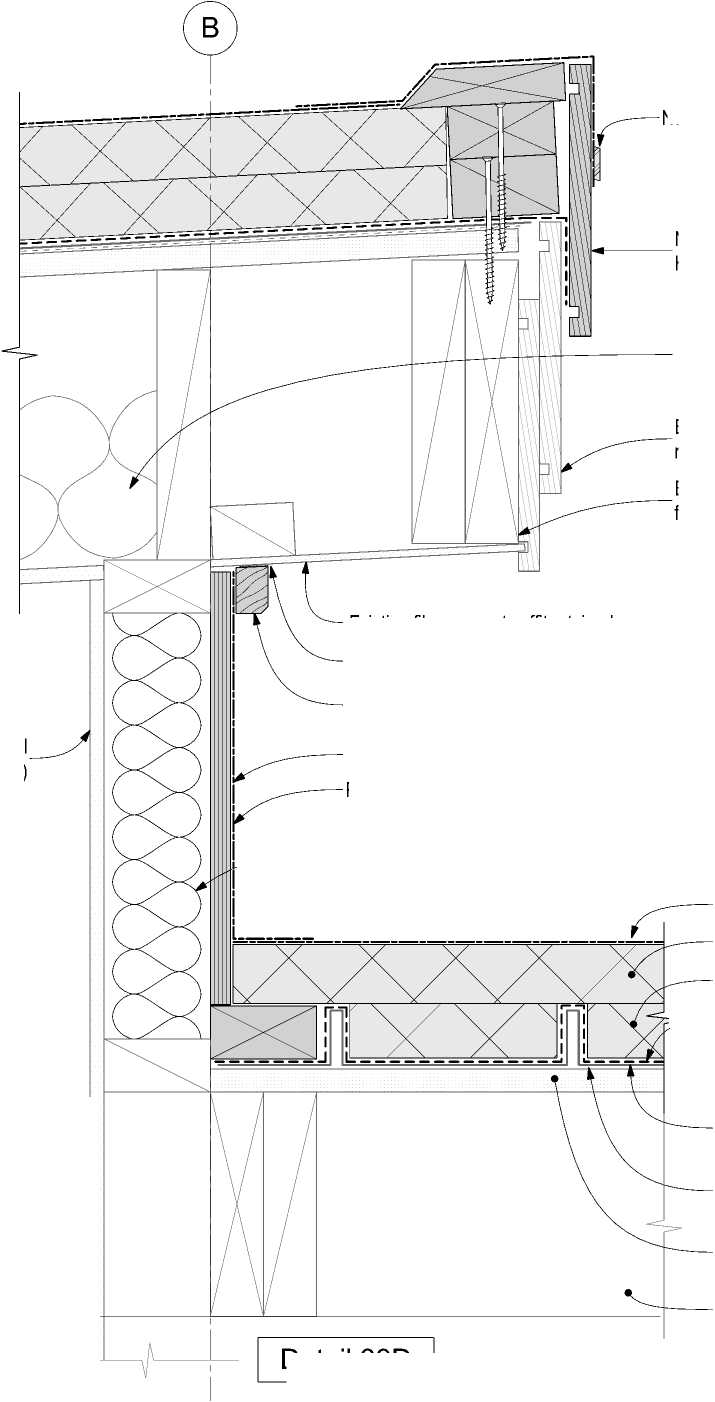 |
Timber eaves mould 40x27, H3.1. Paint finish. Existing fibre cement soffit retained. Continuous sealant bead. |
|
Detail 39D | ||
New pressure bar
New fascia board, H3.2, Paint finished.
Existing insulation *Remove if practical to remove, Refer to Keynote 4711P on Sheet 001.
Existing fascia boards retained if suitable C.O.S.
Existing timber framing (Indicative).
Single ply membrane.
Plywood subtrate 17 Min. H3.2 CCA.
New wall insulation to extend continuously up to the underside of the new insulated overlay roof system if practicable. Refer to Keynote 4711P on Sheet 001.
Single ply membrane
PIR board (tapered).
PIR infill fillet.
New vapour barrier
New overlay roof system installed over existing metal tray clad roof.

|
Existing framing. Window installation. refer Detail 14. | |
|
Ridge of N-S roof above. uPVC back flashing from soffit of roof above to bottom of fibre cement cladding. Fibre cement cladding on cavity on existing wall framing. | 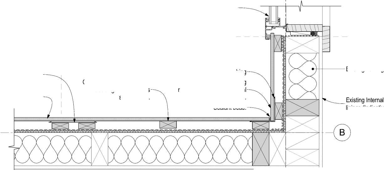 |
|
Fascia of E-W roof above. |  |
Cavity batten spacing as per cladding manufacturers specification.
uPVC corner back flashing
Fixings as per cladding manufacturers cavity internal corner detail.
Sealant bead.
Detail 39A
linings (Indicative)
The contractor shall confirm all conditions and dimensions on site before proceeding with work. Do not scale dimensions off drawings. Contractor is to report any discrepancies to the architect immediately. Plans to be read in conjunction with the specification. RIA accepts no responsibility for any changes made to the issued documents.
| |||||||||||||||||||||||||||||||||||||||||||||
|
Copyright RESOLVEiTARCHITECTS 2022© |
Existing tray profile roof cladding to remain.
Existing original membrane containing asbestos.
Existing original roof substrate (Indicative).
Existing roof structure (Indicative).
Existing metal clad roof remains.
|
uPVC back flashing from soffit of roof above to bottom of fibre cement cladding. Existing fascia board retained if suitable C.O.S. Aluminium pressure bar. Fibre cement cladding on cavity on existing wall framing. New fascia board, H3.2, Paint finished. Fascia of E-W roof above. Existing timber roof framing (Indicative). |
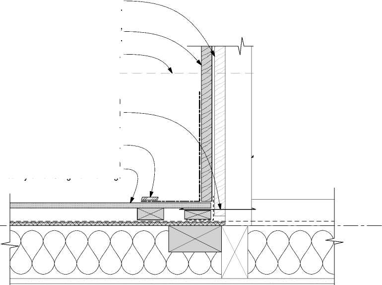 |


Detail 39B
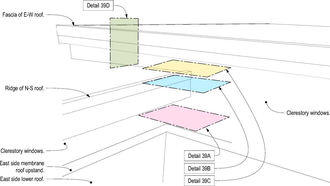
 |
|
Existing fascia board shown dashed. |
Ridge of roof below.

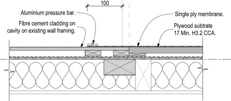
Detail 39C
39 Exterior Detail
112 1:5


RESOLVE1:
ARCHITECTS
LEVEL 1, 171 VIVIAN STREET, TE ARO
PO BOX 9792, WELLINGTON
RESOLVEiTARCHITECTS.CO.NZ
Client:
Naenae College
Project Name: Project Number: R21112
Naenae College
Administration Exterior
Project Address:
910 High Street Avalon Hutt City
|
Status: WRP Review & ProcurDate:t 15/08/2022 Scale: 1:5 Size: A2 | ||||
|
CAD File: S:\Projects\R21112 - Naenae College Roof Remediation\A-Cad\R21112 Naenae College Admin Block-Developed Design 220727.pln
The contractor shall confirm all conditions and dimensions on site before proceeding with work. Do not scale dimensions off drawings. Contractor is to report any discrepancies to the architect immediately. Plans to be read in conjunction with the specification. RIA accepts no responsibility for any changes made to the issued documents.
Rev. Description Date
|
Copyright RESOLVEiTARCHITECTS 2022© |
 |

RESOLVE?
ARCHITECTS
LEVEL 1, 171 VIVIAN STREET, TE ARO PO BOX 9792, WELLINGTON
RESOLVEiTARCHITECTS.CO.NZ
Client:
Naenae College
Project Name: Project Number: R21112
Naenae College
Administration Exterior
Project Address:
910 High Street Avalon Hutt City
Drawing Title:
Joinery
Status: WRP Review & ProcurDate:t 15/08/2022
Scale: Size: A1
Drawing No. Revision No.
CAD File: S:\Projects\R21112 - Naenae College Roof Remediation\A-Cad\R21112 Naenae College Admin Block-Developed Design 220727.pln
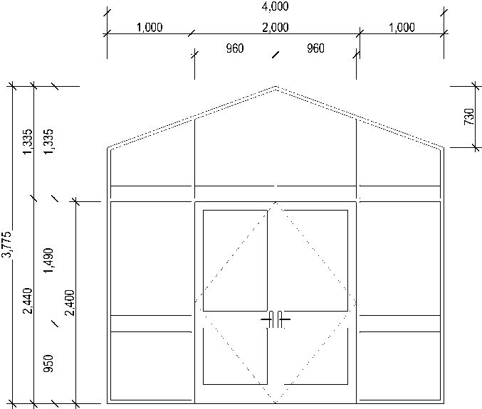
1 item (nD01)
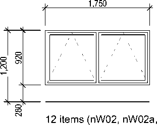
1,400
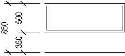
nW02b, nW02c, nW02d, nW02e, nW02f, nW02g, nW02h, nW02i, nW02j, nW02l)
1 item (nW03)
The contractor shall confirm all conditions and dimensions on site before proceeding with work. Do not scale dimensions off drawings. Contractor is to report any discrepancies to the architect immediately. Plans to be read in conjunction with the specification. RIA accepts no responsibility for any changes made to the issued documents.
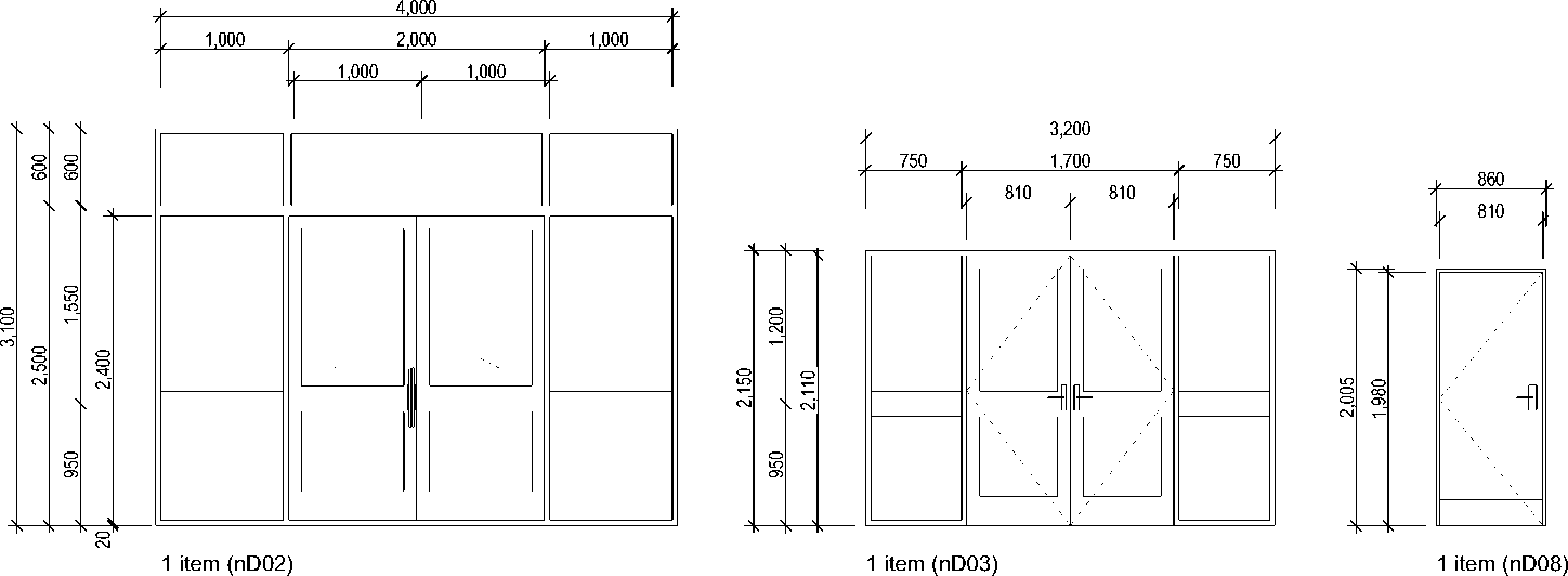
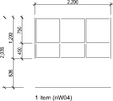
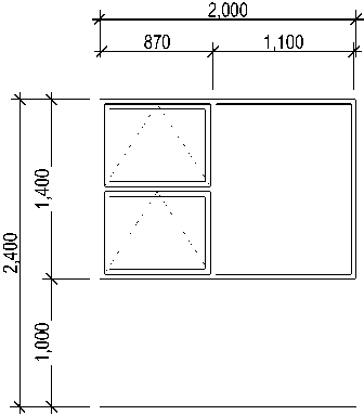
2 items (nW05, nW08)
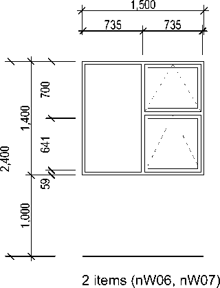
1,100
| |||||||||||||||||||||||||||||||||||||||||||||
|
Copyright RESOLVEiTARCHITECTS 2022© |
11 items (nW01a, nW01b, nW01c, nW01d, nW01e, nW01f, nW01g, nW01h, nW01i, nW01j, nW01k)
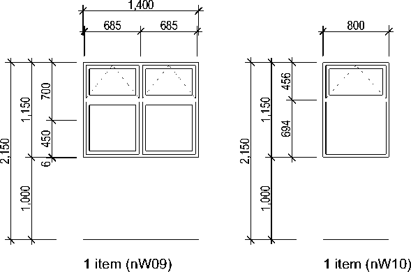
RESOLVE';
ARCHITECTS
LEVEL 1, 171 VIVIAN STREET, TE ARO
PO BOX 9792, WELLINGTON
RESOLVEiTARCHITECTS.CO.NZ
Client:
Naenae College Q
_
Project Name: Project Number: R21112
Naenae College
Administration Exterior
Project Address: g
910 High Street Avalon Hutt City |
g
Drawing Title:
Joinery Schedule I
Project Budget Summary
Naenae College : Interior & Exterior Admin Upgrades
Date 11/12/2022
JR GR^UP
PLAN 0£$ICN 0£LtV£A
|
Item |
Description |
Quantity |
Unit |
Rate |
INTERIOR |
EXTERIOR |
TOTAL |
Comments |
|
1.0 |
Main Contractor - PBJ Construction | |||||||
|
1.1 |
Exterior |
$ 1,095,388.01 |
sum |
1 |
$ 1,095,388.01 |
Quoted sum | ||
|
1.2 |
Interior |
$ 690,654.04 |
sum |
1 |
$ 690,654.04 |
Quoted sum | ||
|
1.3 |
Removal of Autex feature walls |
-$ 7,000.00 |
sum |
1 |
-$ 7,000.00 | |||
|
Section Total |
$ 683,654.04 |
$ 1,095,388.01 |
$ 1,779,042.05 | |||||
|
2.0 |
Provisional Sums | |||||||
|
2.01 |
Structural Steel |
$ 15,000.00 |
sum |
1 |
$ 15,000.00 | |||
|
2.02 |
Window winders and control gear |
$ 15,000.00 |
sum |
1 |
$ 15,000.00 | |||
|
2.03 |
Master Keying |
$ 2,500.00 |
sum |
1 |
$ 2,500.00 | |||
|
2.04 |
HWC connection to toilets |
$ 2,000.00 |
sum |
1 |
$ 2,000.00 | |||
|
2.05 |
Solatube systems |
$ 4,000.00 |
sum |
1 |
$ 4,000.00 | |||
|
2.06 |
Electrical DB upgrade |
$ 5,000.00 |
sum |
1 |
$ 5,000.00 | |||
|
2.07 |
Autex colour mix (one colour allowed for) |
$ 1,000.00 |
sum |
1 |
$ 1,000.00 | |||
|
Section Total |
$ 10,500.00 |
$ 34,000.00 |
$ 44,500.00 | |||||
|
3.0 |
Professional Fees | |||||||
|
3.01 |
PM Exterior Fee |
$ 1,129,388.01 |
Sum |
4.38% |
$ 49,467.19 | |||
|
3.02 |
PM Interior Fee |
$ 694,154.04 |
Sum |
4.38% |
$ 30,403.95 | |||
|
3.03 |
IRG Design |
$ 19,200.00 |
Sum |
1 |
$ 19,200.00 | |||
|
3.04 |
Resolve It Design |
$ 70,000.00 |
Sum |
1 |
$ 70,000.00 | |||
|
3.05 |
Stephenson Turner |
$ 5,000.00 |
Sum |
50% |
$ 2,500.00 |
$ 2,500.00 | ||
|
3.06 |
Spencer Holmes |
$ 8,000.00 |
Sum |
1 |
$ 8,000.00 | |||
|
3.07 |
Exterior BC - HCC |
$ 6,000.00 |
Sum |
1 |
$ 6,000.00 | |||
|
3.08 |
Interior BC - HCC |
$ 8,000.00 |
Sum |
1 |
$ 8,000.00 | |||
|
3.09 |
MCG Asbestos Survey |
$ 5,175.00 |
Sum |
1 |
$ 5,175.00 | |||
|
3.10 |
Simx Ventilation Design |
$ 200.00 |
Sum |
1 |
$ 200.00 | |||
|
3.11 |
Pharaoh Construction |
$ 1,098.00 |
Sum |
1 |
$ 1,098.00 | |||
|
3.12 |
Tracer Construction |
$ 2,629.00 |
Sum |
1 |
$ 2,629.00 | |||
|
3.13 |
GRJ Developments |
$ 1,271.07 |
Sum |
1 |
$ 1,271.07 | |||
|
3.14 |
LB White |
$ 1,536.85 |
Sum |
1 |
$ 1,536.85 | |||
|
Section Total |
$ 58,103.95 |
$ 149,877.11 |
$ 207,981.06 | |||||
|
4.0 |
Contingencies | |||||||
|
4.1 |
Project Exterior Contingency |
$ 1,279,265.12 |
Sum |
15.00% |
$ 191,889.77 | |||
|
4.2 |
Project Interior Contingency |
$ 752,257.99 |
Sum |
12.50% |
$ 94,032.25 | |||
|
Section Total |
$ 94,032.25 |
$ 191,889.77 |
$ 285,922.02 | |||||
|
Total Project Estimate |
$ 846,290.24 |
$ 1,471,154.89 |
$ 2,317,445.13 |